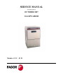
1
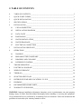
SERVICE MANUAL ********* OCTOBER 2007 GLASSWASHER Models: LVC – 21 W 0 TABLE OF CONTENTS 0 TABLE OF CONTENTS ______________________________________________________ I 1 QUICK START GUIDES______________________________________________________ 1 2 QUICK INSTALLATION _____________________________________________________ 2 3 SPECIFICATIONS ___________________________________________________________ 3 4 INSTALLATION ____________________________________________________________ 4 4.1 VISUAL INSPECTION _____________________________________________________ 4 4.2 INSTALLATION DIAGRAM ________________________________________________ 4 4.3 DATA PLATE ____________________________________________________________ 5 4.4 POSITIONING ____________________________________________________________ 5 4.5 WATER INSTALLATION___________________________________________________ 5 4.6 WATER DRAINAGE_______________________________________________________ 6 4.7 ELECTRICAL CONNECTION _______________________________________________ 7 5 INSTALLATION CHECKLIST_________________________________________________ 8 6 OPERATIONS ______________________________________________________________ 9 6.1 WASHING _______________________________________________________________ 9 6.2 PREPARING THE GLASSWARE ____________________________________________ 9 6.3 DRAINING AND CLEANING ______________________________________________ 10 6.4 DETERGENT CONTROL __________________________________________________ 11 7 TROUBLESHOOTING ______________________________________________________ 12 8 ELECTRICAL DIAGRAM ___________________________________________________ 15 9 WIRING SCHEMATIC ______________________________________________________ 16 10 TIMER (M) ________________________________________________________________ 18 11 SELECTOR SWITCH (IG) ___________________________________________________ 18 12 DETERGENT PUMP NEW LOCATION LVC-21W _______________________________ 19 13 DELIMING ________________________________________________________________ 20 14 RECOMMENDED SPARE PARTS_____________________________________________ 20 15 WARRANTY GUIDELINES __________________________________________________ 21 WARNING: Improper installation, adjustment, alteration, service or maintenance can cause property damage, injury or death. Read this manual thoroughly before installing or servicing this equipment. We recommend all service performed by an authorized service technician. Follow the instructions and guidelines to ensure that your warranty remains in effect. I Level Dishwasher x x x x x x x Electrical Connection Single Phase Fig. 5 Data Plate (located on the right side lower panel) Fig. 1 Three Phase Fig. 6 Fig. 3 To Dishwasher: 90˚ side plus gasket To Wall: Straight side + filter x 3/4”fitting (3/4” Garden hose adapter supplied if needed) Hot Water Connection Fig. 4 Min. 140˚ F (60˚C) @ 20 psi flow pressure x Use 5’ flexible water supplied hose (Fig. 1) x Install filter and gasket supplied x Second Chemicals x Use Commercial Grade, High Temperature, Low Suds Liquid Detergent! Dishwasher comes standard with built-in Adjustable Detergent and Rinse Pumps x On the back of the Dishwasher, locate clear tube marked as “Detergent” and place inside detergent container. (Fig. 7) x The unmarked clear tube is to be placed inside your rinse container. (Fig. 7) x Contact Fagor to install an External Chemical Pump Fifth Fig. 7 Fig. 2 Drain Hook Up Open Drain required 1-1/2” minimum I.P.S. Use grey flex drain supplied (Fig. 2). Clamp it, so remains in place. x Max. Drain Height LVC-21W - 26-3/4” FI-48/64W - 31-1/2” FI-72W - 10” x x x Third Run Machine to verify that all electrical, water and drain hookups are correct, chemicals amount are adequate and there are no leaks! Remove Top and back panel to access to terminal block (Fig. 3) Check Data Plate (Fig. 4) to verify Voltage and Phase. Verify Terminal Block Connection. Single Phase (Fig. 5). Three Phase (Fig.6) When power cord is supplied, verify the connection has not be loosen upon shipment. Check Amps Consumption on Data Plate to size breaker correctly. Replace the back and top panel. Careful not pull out any wires. Write the Model and Serial number in the manual and keep in a safe place. Fourth x Place Dishwasher in permanent location x Level Dishwasher with 4 leveling feet x Level front to back and side to side First All Plumbing and Electrical Connections must be made by a qualified installer in accordance with your state and local codes! LVC-21W / FI-48W / FI-64W / FI-72W Quick Installation Guide 3 SPECIFICATIONS Model: LVC-21W PERFORMANCE/CAPACITIES Capacities Racks per hr.: 22 Wash Tank: 4gal. / 15.4 liters Heating Elements Electric wash tank heater: 2 Kw Electric booster heater: 2.8 Kw Water Consumption / Requirements Gallons per hr. (Max. use): 20gal. / 75 liters Gallons per cycles: .64gal. / 2.4 liters Inlet temperature (Optimum): 140ºF / 60ºC Flow rinse pressure: 15 – 25 psi Operating Cycles Wash time (Seconds): 100 Dwell (Seconds): 5 Rinse time (Seconds): 15 Total Time (Seconds): 120 Wash Pump Motor Motor (hp): 1/3 Dimensions / Shipping Width: 20“ / 508 mm Depth: 24 ½“ / 622 mm Height: 34 ½“ / 876 mm Max clearance for glassware: 10 ½ “/ 267mm Rack: 16“ / 400mm Shipping weight: 105 lbs. / 47.5 kg Shipping volume (cu. ft.): 10 Temperatures Wash: 150ºF / 66ºC Rinse: 190ºF / 88ºC TECHNICAL SPECIFICATIONS Total Power Consumption Volts Amps Power (KW) 208/60/1 13.1 2.7 220/60/1 14.7 3.2 240/60/1 15 3.6 Boiler Power Consumption Volts Amps Power (KW) 208/60/1 12 2.5 220/60/1 13.5 3.0 240/60/1 13.75 3.3 Pump Power Consumption Volts Amps Power (KW) 208/60/1 1.10 .23 220/60/1 1.18 .26 240/60/1 1.25 .3 3 4 INSTALLATION 4.1 VISUAL INSPECTION Upon receiving your new Fagor dishwasher, check the package and the machine for any damages that may have occurred during transportation. Visually inspect the exterior of the package. If damaged, open and inspect the contents with the carrier. Any damage should be noted and reported on the delivering carrier’s receipt. In the event that the exterior is not damaged, yet upon opening, there is concealed damage to the equipment notify the carrier immediately. Notification should be made verbally as well as in written form. Request an inspection by the shipping company of the damaged equipment. Also, contact the dealer through which you purchased the unit. 4.2 INSTALLATION DIAGRAM R P T R 32 7/8" 18 1/2" 4" 2 1/2" 28 1/3" 12 9/16" 10 1/4" 20 1/2" 6 7/8" ~2" 8 1/4" Installation with drain motor pump Max.26 3/4" 10 5/8" A = Water inlet D = Drain hose E = Electrical Cable R = Terminal Block Fig. 1 4 E A D 4.3 DATA PLATE The data plate in located on one side of the machine. Under no circumstances should the data plate be removed from the unit. The data plate is essential to identify the particular features of your machine and is of great benefit to installers, operators and maintenance personnel. It is recommended that, in the event the data plate is removed, you copy down the essential information in this manual for reference before installation. Any transformations or changes made on the machines during installation should be reflected on the data plate. 4.4 POSITIONING Leveling and adjusting the height of the appliance is done by turning the leveling stands (Fig. 2) to the desire height. Ensure that the unit is level (front to back, side to side) before making any connections. Fig. 2 4.5 WATER INSTALLATION Water installation is carried out as shown in figures 3 and 4. The hot water line to the glass washer must provide between 20±5 psi of water pressure. The hot water heater should be set to deliver ≥140°F (≥60°C) water temperature to the glass washer for best results. Use ¾” copper tubing inlet line. P P S =Gate Valve F = Filter H = Hose E = Fill valve M = Pressure Gauge R = ¾” Copper Fig. 3 CAUTION: Do not confuse static pressure with flow pressure. Static pressure is the line pressure in a “no flow” condition (all valves and services are closed). Flow pressure is the pressure in the fill line when the solenoid valve is opened during the cycle. 5 THE DISPLAY OF THE PRESSURE GAUGE SHALL BE CLEARLY VISIBLE OF THE OPERATOR OF THE MACHINE. THE GAUGE SHALL HAVE INCREMENTS OF 1 psi (7 kpa) OR SMALLER AND SHALL BE ACCURATE TO ±2 psi (±14 kpa) IN THE 15-25 psi (103-172 kpa) RANGE. IF THE GAUGE IS LOCATED UPSTREAM OF THE CONTROL VALVE, IT SHALL BE MOUNTED IN AN ACCESSIBLE VALVE WITH A ¼ IN IRON PIPE SIZE CONNECTION. If the water pressure is less than 20 psi (1.4 kg/cm2), installation of a water pump is required as shown in Fig. 4. In areas where the pressure fluctuates or is greater than the recommended pressure, it is suggested that a water pressure regulator be installed. P P S = Gate Valve F = Filter H = Hose E = Fill valve B = Electro pump M = Pressure Gauge R = ¾” Copper Fig. 4 It is necessary to remove all foreign debris from the water line that may potentially get trapped in the valves or cause an obstruction, prior to connecting to the machine. Use only the supplied hoses (3/4” Female hose connector) at the water connections. Failure to do so may result in damage to the solenoid valve threads and leaking. Tighten by hand. Connect the bent side of the hose to the machine. Adaptor supplied for ¾” female garden hose connection. For hard water supplies with a hardness of over 2 grains or 10ºF and ph beyond the range of 7.0 – 8.5, a water conditioner must be installed. Slowly turn on the water supply to the machine after the incoming fill line and the drain line have been installed. Check for any leaks and repair as required. All leaks must be repaired prior to placing the machine in operation. 4.6 WATER DRAINAGE Attach the drain hose as shown in Fig. 5. It is recommended to affix a siphon pipe to prevent odors. All piping from the machine to the drain must be a minimum 1-1/2” I.P.S. There should also be an air gap between the machine drain line and the drain. For natural overflow efficiency use floor drain. 2 3/8" D = Drain hose C = Drain collector A = Air gap F = Scrap Basket Fig. 5 6 4.7 ELECTRICAL CONNECTION − To access to the electrical connection block (R) (Fig. 1), remove the top cover (T) (Fig. 1) and the rear panel (P) (Fig. 1). Connect the wires as shown in figure 6. Insert the power cord through the cord holder (E) (Fig. 1) and make sure to leave enough cable to remove the electrical panel from the front for service. Tighten the connections. − Leave free ≥ 39” (≥ 1000 mm) of power cord from the rear to facilitate cleaning of the location of the glass-washer. − Install a circuit breaker according to required consumption guidelines (Page 1) and data plate. − The machine must be grounded. Terminal Block Connection (208-220-240V 1Ph) Ground Ground Input Line Input L Yellow/ Green BLACK CAP – Red Wire BROWN CAP – Red Wire BLUE CAP - Red Wire Neutral Input N BLUE CAP – Red Wire Fig. 6 WARNING: Electrical Shock Hazard It is the personal responsibility and obligation of the customer to contact a qualified electrician to assure that the electrical installation is adequate and is in conformance with the National Electrical Code, ANSI / NFPA 70 – latest edition and all local codes and ordinance. 7 5 INSTALLATION CHECKLIST CHECK OFF THE FOLLOWING ITEMS AS THEY ARE COMPLETED BEFORE PROCEEDING TO OPERATE OR SERVICE THE GLASSWASHER. Has the dishwasher been checked for concealed/hidden damage? Has the dishwasher been properly leveled? Has the service voltage been checked to ensure that it meets the requirements listed on the dishwasher data plate? Has the dishwasher circuit breaker/service breaker been sized correctly, given the dishwasher’s amperage requirements? Has the dishwasher been properly grounded? Are the electrical connections and pipes tighten and remain in place? Is the water valve open? Is the incoming water supply at 15 - 25 psi? Has been installed with the supplied water hose? Is the water hose not kinked? Has the incoming water supply been flushed for debris? Is the hot water supply at the optimum temperature (140ºF)? Is the water hardness ≤2.0gpg/34.2ppm and PH level 7 - 8.5ph ? Has the drain plumbing been installed according to the instructions in this manual? Is the drain hose not kinked? Is the overflow tube with the O-ring fitted in its position inside the tank Is the detergent for commercial dishwashers? Have you adjusted the amount of detergent / rinse going to the machine? MODEL NO.___________________________ SERIAL NO.___________________________ INSTALLATION DATE _________________ SERVICE REP. NAME __________________ PHONE Nº ____________________________ 8 6 OPERATIONS 6.1 WASHING Fig.8 Control Panel • • Set selector switch (1) to . This will turn your machine ON. Indicator light (2) will illuminate. Machine will automatically begin to fill and heat the water in the boiler and tank to the proper temperatures. Wait for the rinse gauge (3) to read ≥ 180º F (83˚C) and your wash tank gauge (4) to read ≥ 150º F (66˚C). (Time will vary depending on incoming water temperature) Note: To speed up the warm up process, you can run the Dishwasher a couple of times only after the Rinse Gauge (3) is ≥ 180º F (83˚C). • • • • Open the door, load your dishwasher and close the door. Start the wash by pressing and holding your start button (4) until your machine begins to wash. Start switch (4) will illuminate during operation. Wash is completed when the start button (5) turns off. Open the door and repeat process. COOL RINSE Cool rinse provides your glasses with fresh water based on your incoming water temperature to cool them down from your 180º F (83˚C) final rinse. For a cool rinse, turn and hold the switch (1) to the setting (Fig. 8) for operator’s desire amount of time and release. 6.2 PREPARING THE GLASSWARE - Remove the big pieces of food from items before putting in the baskets. Put glasses in upside down. Put dishes in the available accessory for this purpose. Put cutlery in the cutlery baskets handles down. Spoons, knives and forks can be mixed. Put the special cutlery baskets in the base basket. 9 6.3 DRAINING AND CLEANING Draining must occur EVERY DAY and if in a high application; It should be drained after each meal rush! Fig.8 Control Panel • Switch selector switch (1) to the 0 setting. (OFF) (Fig. 8) • Remove the overflow tube by inserting a finger into the top of the tube. (Fig.10) • • • • • • • • • DO NOT REMOVE SCRAP BASKET! DO NOT LOOSE O’RING! Close the door. Set selector switch (1) to for drain. Depress the start button (4) to start the drain pump. Start Button (4) will illuminate. Wait until the Start Button (4) turns off. (3 minutes) Open door. Take out scrap basket for cleaning by twisting to the left. (Fig. 11) Replace scrap basket, lock into position by twisting to the right and replace overflow tube with O-ring. Switch selector switch (1) back to the OFF position. Wipe clean and dry the machine if the day is completed. Leave door open until the next day’s operations or to the time settings to begin using the machine again. 10 6.4 DETERGENT CONTROL • • • • • • • • USE Commercial Grade, High Temperature, Low Suds Liquid Detergent. Fagor doesn’t recommend any specific brand name of chemicals. Contact your local chemical distributor for questions concerning your chemical needs. All machines come equipped with an internal Detergent and Rinse dispenser. Take the tube located in the back or your machine clearly marked “Detergent” and place inside detergent container. Take the tube with no markings and place inside rinse container. Tubes are clear to provide you a visible means that chemicals are being dispensed. If desired you can control the amount of Chemical being dispensed by opening the bottom front panel of the machine. Locate the detergent dispenser (Fig. 12) and regulate according to flow chart (Fig. 12a). For the Rinse, turn the button counterclockwise to get more rinse aide and clockwise for less. You prime the line by depressing the button. Verify all connections to the dispenser are hand tighten to prevent any leaks. Control and maintain the level of detergent and rinse aid of the tanks. Keep pipe and filters submerged. 220º 7 6 Oº 1 2 3 5 4 Fig. 12a 1 2 3 4 5 6 7 Gal./h. 0 0.06 0.20 0.40 0.53 0.66 0.80 Fig. 12 Rinse Controller and Priming Button Detergent Controller Warning! If you require the installation of an NON FAGOR Detergent and Rinse pump, a form MUST be fill out prior to installation by your installer. Failure to do so, will void your Warranty. This form can be located inside your dishwasher. If lost, please contact Fagor to get a copy.. 11 7 TROUBLESHOOTING First be sure that the “INSTALLATION CHECKLIST” in this manual was completed and check out that all the conditions still remains in effect. For support or further service information contact Fagor Service Department toll free at 1-866-GO-FAGOR (46-32467). The diagnosing, testing and repair of any electrical, mechanical device is to be performed solely by trained service technicians. SYMPTOM POSSIBLE CAUSE Glasswasher will NOT FILL after the door is closed. Power “ON” light (L1) is not illuminated. Service breaker tripped Glasswasher will NOT FILL after the door is closed. Power “ON” light (L1) is illuminated. No water to machine Machine not connected to power source. Faulty selector switch (Ig) Machine not level Overflow tube not attached or broken / missing O-ring. Faulty door switch Faulty fill pressure switch (P1) Faulty fill valve (V1) Glasswasher will NOT RUN after the door is closed. Power “ON” light (L1) is illuminated and the unit has completed the filling and heating cycle. Fill pressure switch’s pipe clogged Faulty fill pressure switch (P1) Start button (St) faulty ACTION Reset. If the breaker trips again, contact an electrician to verify amps or possible short. Verify the unit is connected to a hot (live) feed. Verify voltage and proper phasing. Verify the wiring of the switch; if correct, replace the switch. (Position 4-4a / 8-8a) Verify hose is not blocked or kinked, water valve is open and pressure > 20 PSI. Level machine. Legs are height adjustable. Check condition of overflow tube. Verify the wiring of the switch; if correct, replace the switch (Ip) or the door relay (Rp) Verify position change 1-2 / 1-3 to pressure switch. Possibly stuck . Verify the wiring and voltage received; if correct replace fill valve. Drain the unit, fill again, even manually and run a cycle Verify it changes position of the switch; If not replace it. Verify start button is operating properly. If not replace it. Faulty Timer (M) Verify the timer is rotating (M1, M2 & M3). If not, check to see that the motor is receiving power. If so, replace the timer assembly. Ohm out timer motor leads. Faulty wash pump (MBL) Verify that the wash pump is getting power. If so, replace the pump. Ohm out windings. Verify voltage at (1,2 to1a) at selector switch Selector switch faulty (IG) 12 SYMPTOM POSSIBLE CAUSE Timer faulty (M) Glasswasher RUNS continuously in the wash cycle or not rinsing. Faulty rinse valve (V1) No water to machine. Glasswasher FILLS slowly and/or rinse is weak. Clogged or obstructed rinse arms Poor water pressure Hose strainer is clogged Bad fill valve (V) Temperature gauge in front panel is defective. Misadjusted/faulty thermostat (Tc) Glasswasher RUNS. RINSE WATER NOT REACHING REQUIRED TEMPERATURE. Faulty high limit stat (Tl) Faulty heater relay (Cc) Rinse heater (Rc) faulty Bad selector switch (IG) Glasswasher RUNS. WASH WATER NOT REACHING REQUIRED TEMPERATURE. Wrong incoming water and pressure going to the machine. Faulty operation t-stat (Tc) Misadjusted/faulty thermostat (Tt) Tank heater relay (Ct) faulty. Rinse heater (Rt) faulty 13 ACTION Verify the programmer is rotating (M1, M2, M3). If not, check to see that the motor is receiving power. If so, replace the programmer assembly. Ohm out timer motor leads. Verify the wiring and voltage received; if correct, ohm out. If open replace valve. Verify hose is not blocked or kinked, water valve is open and pressure > 20PSI. Remove and clean rinse arms/nozzles. Verify the inlet water pressure is at a min of 15 psi and max 25 psi. Check strainer or any filters installed. Valve can be clogged or lazy, causing poor flow. Check temperature with a calibrated thermometer. Replace temperature gauge if necessary. Verify operation and setting of thermostat; replace if necessary. If thermostat is not receiving voltage, check wiring or replace selector switch (IG) Reset thermostat, depressing red button. Replace if necessary. Ohm out booster relay, closed when solenoid receiving voltage. If not replace. Ohm out element check for continuity; if open, replace heater. Verify voltage between positions (6/6a) (Pk/r); replace if no voltage. Check out that incoming water temperature and pressure are the optimums indicated on the data plate. Verify position change to tank t-stat (Tt); replace if necessary. Verify voltage to t-stat and position change from booster to tank. Verify contacts are close when there is voltage to relay also check for stuck or pitted contacts. Check element for continuity; if open, replace heater. SYMPTOM Glasswasher RUNS perfectly but NOT DRAINING. Dishes are not coming out clean enough. POSSIBLE CAUSE Overflow tube not removed. Check and remove. Drain pump (BD) clogged. Open drain pump cover and remove debris. (Lower front panel; unscrew white removable cover, rotate c/cw) Make sure the drain hose is not kinked Drain hose kinked Drain pump (BD) faulty Verify voltage to drain pump; if receiving voltage, ohm out drain pump if open, replace it. Faulty safety pressure Verify position changes from (1-3 to-1-2) switch (P2) Machine temperatures or pressure may not be to specification. None or too little detergent being used. Verify that the water pressure is at a min. of 15psi and max 25 psi. The water temperature should be at the recommended 140 F. Make sure detergent to dish ratio is fallowed to manufacturer specification. Improper loading or overloading Read chapter on proper loading of dishwasher. Washing and or rinsing arms jammed or dirty. Check that arms rotate properly, and that rinsing and washing nozzles are not blocked or dirty. Clean if necessary Remove instruction form the pump or from the pipe Clogged drain WATER OVERFLOW FROM BOTTOM OF THE DOOR ACTION Machine not level Level machine. Increase height to the front Excessive inlet pressure Install pressure reducing valve. Ensure flow is 15-25 PSI DETERGENT FOAMING Use detergent for commercial appliances. Reduce detergent quantity 14 8 ELECTRICAL DIAGRAM 15 9 WIRING SCHEMATIC 16 3 r 2S a ve A1 b r a a n am A2 ve ve A1 a 13 m am/ve Z-433011 23 a 22 a m g n vi am n rs n S a 3 N ~ 380-415 V. 7 T am/ve a a a a r n m m vi A2 b1 r r R r r N a1 n 12 n 11 21 N g r 2 Cc Ct Rp vi A Z-213007 L Z-203062 9 2 g g m 2 m rs b ve b rs b vi M 2 g PRG. n ve na am m Ip rs r a b r n ve m vi g rs g am b rs rs Lmp Lm ve r IG ST / LC Calderín Agua Fria ve n C ve m na b A Rc MB am/ve am/ve am/ve b Tt am/ve am na 6 ve A m a ri llo V e r d e Esquema de montaje LVR-20 B; LVC-21 B na Rt na a ve Tl 8 Tc 4 Det. na 2 a n g vi vi Ds 5 ve vi am/ ve r Nº Nº Pieza Material Modificacion Propuesta de B.D. vi r Fecha Sustituir Relé Z203018 por Z203062, cambiar colores en Rp J.M.P.A. 13-5-2002 8 Añadir cable tierra en bomba desague B.D. Santi 25-4-2001 7 Introducir Presostato Z-433011 J.M.P. 19-10-99 6 Introducir Termostato tanque ZERTAN Maillo 14-1-98 Firma S. N. Fecha 19-10-94 Acabado Tolerancias generales 5± . 5 25± . . 25 50± . 100± ± Fagor Industrial,Koop.Elk, Mugatua Plano numero HC-16383-9 Sustituye al N° Plano hau ez daiteke erabil ez berrizta gure baimenitz gabe 17 . 50 100± . Mecanizado superficial LAVAVASOS 2 1 P Nº Clasificacion 9 Dibujado Proyectado Comprobado Escala am/ve Z-433035 Sustituido por 10 TIMER (M) The cycle timer is comprised of 3 sections (M1 to M3). Each one has a 3 position micro switch (line /normally closed /normally open) and 1 drive motor. M1: This is the (ON) cycle micro, and stays activated throughout the completion of the cycle. The M1 line in (violet) wire comes from the press valve (P1) and feeds the (red ) normally closed position to the start switch as well as the (pink ) to normally open position on (M-1) and line in to ( M2/ M3). Also the cycle light and timer motor are fed via this line. M2: Wash sequence micro. In this sector the (pink) line feed supplies the normally open position (grey) line to selector position (#1 & #2). Pump motor (MBL) is energized upon activation of the micro thru position (#1a) down to the motor. Drain pump (BD) is energized upon activation of the micro thru position (#2a) down to the pump. In the normally close position the (yellow) will feed press valve (P2) for drain. M3: the rinse sequence micro. In this sector the (pink) line feed supplies the normally open (white) position to the fill valve (V1). Upon activation the water valve is energized for 15 seconds of rinsing. 11 SELECTOR SWITCH (IG) 0 : When 0 setting is selected, all the contacts are open. : When drainage setting is selected, contacts: 2-2a, 4-4a, 5-5a and 8-8a of the electrical diagram are closed. : When 120 seconds cycle is selected, contacts: 1-1a, 4-4a, 6-6a, 7-7a and 8-8a of the electrical diagram are closed. : When cold rinse setting is selected, contacts: 1-1a, 3-3a, 4-4a, 6-6a, 7-7a and 8-8a of the electrical diagram are closed. 18 12 DETERGENT PUMP NEW LOCATION LVC-21W Detergent Injector B A Hole to fix bracket Fig.1 New Bracket. Part #: Z208909 Button (screw) to adjust detergent amount Pipe going to the tank Second hole; use (1) Screw #Q152004 & (1)Nut #Q162030 to fix the bracket Procedure: 1- Open Front Bottom Panel 2- Be sure that the bracket on the pump is the one shown above (part #: Z208909) 3- If not, attach pump to the bracket (side B – Fig. 1) with (2) bolts, (2) washers and (2) nuts supplied 4- Use screw and nut supplied to hold the bracket (side A – Fig. 1) to the bottom frame of the dishwasher. First hole of the bracket (Fig. 1) fits with the second hole at the frame. 5- Fit detergent pipes on the pump. Check out above to see which one goes to the tank and which one goes to the detergent container. 6- TIGHTEN DETERGENT PIPE CONNECTIONS TO PREVENT UNNECESSARY LEAKS 7- Put back Front Bottom Panel Note: Rinse aid dispenser is built-in and adjustable too. Turn the button counterclockwise to get more liquid during the rinsing and clockwise for less amount. Rinse aid dispenser is located at the left bottom side. When machine is new, in order to prime the rinse aid press the button. 19 13 DELIMING In order to maintain dishwasher at optimum conditions, it is requested to remove lime and corrosion deposits on a frequent basis. A deliming solution should be available from your chemical supplier. Read and follow all instructions on the label of the deliming solution. Operations: • • • • • • • Fill the machine. Add the correct amount of deliming solutions as recommended by the deliming solution manufacturer. The water capacity of the tank can be verified on the specification sheet of this manual Remove detergent and rinsing tubes from containers so no chemicals go to the machine Run the machine for the recommended period of time. As many cycles as needed. Turn off the machine and open the door When clean, drain and re-fill the machine Run machine for 3-4 cycles to remove deliming solution Drain the machine. 14 RECOMMENDED SPARE PARTS Part number P255001 R223005 Z203009 Z203062 Z211903 Z213007 Z393005 Z400709 Z400711 Z401001 Z421711 Z433011 Z448302 Z718441 Z433001 Z223501 V817100 Q307051 Z400907 Z231105 U183046 Z200107 Z651123 1200000132 Description Water fill valve (dual) Tank heating element 2000 W. Door switch Door relay Rinsing nozzle Contactor Boiler thermostat Washing nozzle Washing nozzle bracket Pump motor 60Hz. Boiler heating element 2800W. Pressure switch Timer Tank thermostat General selector switch Drain pump 6 MF Capacitor Gasket for Overflow Tube Overflow Tube Antireturn valve Terminal Block Adjustable Leg Rinse Aid Dispenser Detergent Pump Kit 20 15 WARRANTY GUIDELINES 1. SERVICE ISSUES When a service issue occurs, the end user must call Fagor to report the problem. Our toll free number: 1-866-GO-FAGOR is located in the front of the machine. If the issue can not be resolved by phone, Fagor will contact the closest Authorized Service Agency for assistance and will forward the information regarding the issue. The Agency will be provided with an Authorization Number only if the warranty still remains effective. Serial number of the machine must be provided by the end user or by the service agency to Fagor. Distributors and dealers are not permitted to send Service Agencies without authorization from Fagor’s Service Department. 2. PARTS Service Agencies will be provided with the name of the Parts Distributor in his territory. All orders for parts within the warranty period as well as for parts out of warranty must be sent to the Distributor. Distributor must deliver the part to the Agency. If the Distributor does not have the item in stock, they must order items from Fagor and include shipping information. Parts will be drop shipped from Fagor‘s Warehouse. If the part is under warranty, Agency must provide Distributor with the authorization number given by Fagor, when placing order. Part will be shipped free of charge. Using that number Distributor will fill out the Warranty Parts Form and fax/e-mail it to Fagor at the end of the month . If service agency owns a package of spare parts, it is his responsibility to maintain original quantity of parts in stock. Fagor will not pay second trips for service calls that involve these parts. Service Agency should have the package of spare parts in the van when is attending a service call. 3. INVOICING and SHIPPING of PARTS Under Warranty, Distributor should send the part free of charge to the Service Agency. Distributor will be reimbursed for the part by Fagor or part will be replaced, as soon as the Warranty Parts Form is received. 4. SERVICE INVOICES Service Agency will send the invoice to Fagor in order to be reimbursed, indicating the Authorization Number. No charge for the parts. Use Fagor Warranty Claim Form. CFESA service report Form also permitted. Overtime and estimated invoices higher than $300 must be first approved and authorized by Fagor prior to be performed. 5. DOCUMENTATION Distributors and Agencies will be supplied with the following technical information and documentation: Parts breakdown, Service Manuals, Schematics, Repair sheets and Parts Price List. For your convenience this information will be supplied on electronic format. 21 Fagor Commercial, Inc. 12800 NW 38th Ave. Miami, Fl. 33054 Tel: (305) 779 0170 Fax: (305) 779 0173 1-866-GO-FAGOR www.fagorcommercial.com