1
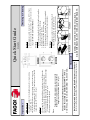
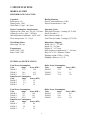
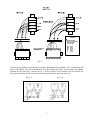
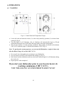
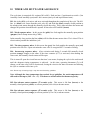
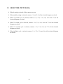
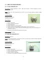
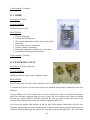
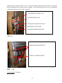
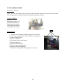
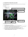
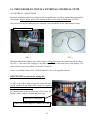
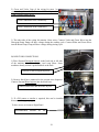
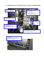
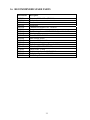
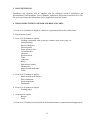
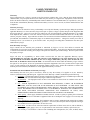
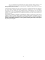
SERVICE MANUAL ********** October 2006 DOOR STYLE DISHWASHER Models: FI - 120 W 0 TABLE OF CONTENTS 0 TABLE OF CONTENTS ________________________________________________________ I 1 QUICK START GUIDES________________________________________________________ 1 2 QUICK INSTALLATION _______________________________________________________ 2 3 SPECIFICATIONS _____________________________________________________________ 3 4 INSTALLATION ______________________________________________________________ 4 4.1 VISUAL INSPECTION _____________________________________________________ 4 4.2 INSTALLATION DIAGRAMS _______________________________________________ 4 4.3 DATA PLATE ____________________________________________________________ 5 4.4 POSITIONING ____________________________________________________________ 5 4.5 WATER INSTALLATION___________________________________________________ 5 4.6 WATER DRAINAGE_______________________________________________________ 7 4.7 ELECTRICAL CONNECTION _______________________________________________ 7 5 INSTALLATION CHECKLIST___________________________________________________ 9 6 OPERATIONS _______________________________________________________________ 10 6.1 WASHING ______________________________________________________________ 10 6.2 DRAINING AND CLEANING ______________________________________________ 11 6.3 PREPARING THE WARE __________________________________________________ 12 6.4 DELIMING ______________________________________________________________ 13 6.5 DETERGENT CONTROL __________________________________________________ 14 6.6 EXTERNAL CHEMICAL PUMP ____________________________________________ 15 7 TROUBLESHOOTING ________________________________________________________ 16 8 ELECTRICAL DIAGRAM _____________________________________________________ 19 9 WIRING SCHEMATIC ________________________________________________________ 20 10 TIMER AND HOT WATER ASSURANCE ________________________________________ 21 11 SELECTOR SWITCH (IG) _____________________________________________________ 22 12 SERVICE PROCEDURES ______________________________________________________ 23 12.1 TANK THERMOSTAT ____________________________________________________ 23 12.2 BOILER THERMOSTAT___________________________________________________ 23 12.3 TIMER _________________________________________________________________ 24 12.4 WATER FILL VALVE_____________________________________________________ 24 I 12.5 WASHING PUMP ________________________________________________________ 26 13 DETERGENT PUMP NEW LOCATION __________________________________________ 27 14 PROCEDURE TO INSTALL EXTERNAL CHEMICAL PUMP ________________________ 28 15 THERMOSTATS CONFIGURATION (AFTER OCTOBER 20006) _____________________ 30 16 RECOMMENDED SPARE PARTS_______________________________________________ 32 17 WARRANTY GUIDELINES ____________________________________________________ 33 6. REASONABLE TIMES TO REPAIR AND REPLACE PARTS ______________________ 34 WARNING: Improper installation, adjustment, alteration, service or maintenance can cause property damage, injury or death. Read this manual thoroughly before installing or servicing this equipment. We recommend all service performed by an authorized service technician. Follow the instructions and guidelines to ensure that your warranty remains in effect. II To speed up the warm up process, you can run the Dishwasher a couple of times only after the Rinse Gauge (4) is at least 180º F (83ºC). (Fig 2) x Figure 2 (Refer to your Operations Manual for Pump Priming and Adjustment instructions) Figure 3 Figure 4 Figure 5 (Refer to Operations Manual for detailed instructions) Deliming 1. Switch selector switch (1) to Continuous Wash. (5) 2. Place Deliming agent in tank and lower hood. Figure 6 1. Remove the rack guide (Fig. 5), Bulk and Long Scrap Baskets (Fig.3), and Filter (Fig. 4) for clean. 2. Replace all back into position. 3. Replace the overflow tube with O-ring. 4. Wipe clean and dry the machine if the day is completed. Leave hood open until the next days operations. DETERGENT MUST BE COMMERCIAL GRADE, HIGH TEMPERATURE, LOW SUDS, LIQUID DETERGENT. Chemicals Built-in Adjustable Detergent and Rinse Dispensers are Standard If you start your dishwasher prior to your booster heater (4) reaching a minimum of 180º F (83ºC), YOU WILL HAVE AN EXTENDED WASH CYCLE. Notes: 1. Pre scrap all ware thoroughly prior to placing in your Dishwasher. 2. Set your Selector Switch (1) to the desired time setting (8). 3. Raise hood, load the dishwasher and lower the hood, Indicator light (7) will illuminate during the wash cycle. 4. Repeat process when completed. Washing Cleaning 1. Switch selector switch (1) to the “0” setting. (OFF) (Fig.1) 2. Raise hood and remove the overflow tube to drain your unit. (Fig. 6) DO NOT LOOSE O’RING! 1. Set selector switch (1) to the Standby mode (2) or desired time setting (8). (Fig. 1) 2. Wait for the machine to reach operating conditions. Rinse gauge (4) should read minimum 180º F (83ºC) and tank gauge (5) should read minimum 150º F (66ºC). (Fig. 2) Figure 1 Draining Draining & Cleaning Fill & Warm up Operations FI-120W Quick Start Guide x x x Drain x x x x x x x Parts inside Electrical Connection Fig. 1 Fig. 4 Data Plate (located on the right side lower panel) Fig. 6 Three Phase Fig. 5 Single Phase Remove front panel to access to terminal block (Right, top side) Check Data Plate (Fig. 4) to verify Voltage and Phase. Verify Terminal Block Connection. Single Phase (Fig. 5). Three Phase (Fig.6) Check Amps Consumption on Data Plate to size breaker correctly. Machine includes electrical connections for external chemical pump. Remove right panel to have access to it. Replace panel. Replace front panel. Careful not pull out any wires. Write the Model and Serial number in the manual. Keep safe. x Place threaded cap T on position (Fig.1) x Insert and push Solenoid E (Fig. 1) until it is fixed. x Connect wiring to the solenoid E. Use gasket between both. Tighten with screw. x Fit Pressure Gauge M (Fig. 1). Use Teflon tape over the thread to prevent leaks. Second x Use Commercial Grade, High Temperature, Low Suds Liquid Detergent! Fig. 7 To Dishwasher: 90˚ side plus gasket Chemicals Fig. 2 To Wall: Straight side + filter x 3/4”fitting (3/4” Garden hose adapter supplied if needed) Hot Water Connection Dishwasher comes standard with built-in Adjustable Detergent and Rinse Pumps. x On the back of the Dishwasher, locate clear tube marked as “Detergent” and place inside detergent container. (Fig. 7) x The unmarked clear tube is to be placed inside your rinse container. (Fig. 7). x Contact Fagor before installing an External Chemical Pump. Failure to do so, will VOID your warranty! Sixth Min. 140˚ F (60˚C) @ 20 psi flow pressure x Use 5’ flexible water supplied hose (Fig. 2) x Install filter and gasket supplied x Third Run Machine to verify that all electrical, water and drain hookups are correct, chemicals amount are adequate and there are no leaks! Fig. 3 Open Drain required 1-1/2” minimum I.P.S. Use grey flex drain supplied (Fig. 3). Clamp it, so remains in place. Fourth x Fifth Level Dishwasher Place Dishwasher in permanent location x Level Dishwasher with 4 leveling feet x Level front to back and side to side First All Plumbing and Electrical Connections must be made by a qualified installer in accordance with your state and local codes! FI-120W Quick Installation Guide 3 SPECIFICATIONS MODEL: FI-120W PERFORMANCE/CAPACITIES Capacities Racks per hr.: 60 Dishes per hr.: 1500 Wash Tank: 11.8gal. / 44.6 liters Heating Elements Electric wash tank heater: 4.5 Kw Electric booster heater: 12 Kw Water Consumption / Requirements Gallons per hr. (Max. use): 48 gal. / 181 liters Gallons per cycles: .8gal. / 3.02 liters Inlet temperature (Optimum): 140ºF / 60ºC Flow rinse pressure: 15 – 25 psi Operating Cycles Wash time (Seconds): 3 settings (35,55,100) Dwell (Seconds): 5 Rinse time (Seconds): 15 Total Time (Seconds): 3 settings (55,75,120) Wash Pump Motor Motor (hp): (2) 1 hp Dimensions / Shipping Width: 28 1/4” / 717 mm Depth: 32” / 813 mm Height: 62” / 1575 mm Max clearance for dishware16 ½” / 419 mm Rack: 20” x 20” / 500mm x 500mm Shipping weight: 330 lbs. / 150 kg Shipping volume (cu. ft.): 32 Temperatures Wash: 150ºF / 66ºC Rinse: 190ºF / 88ºC TECHNICAL SPECIFICATIONS Total Power Consumption Volts Amps Power (KW) 208/60/3 47.6 14.4 220/60/3 50.1 16.1 240/60/3 53.2 19.2 Pump Power Consumption Volts Amps Power (KW) 208/60/3 5.2 1.2 220/60/3 5.4 1.2 240/60/3 6 1.2 Boiler Power Consumption Volts Amps Power (KW) 208/60/3 32.2 9.8 220/60/3 33.8 11 240/60/3 35.4 13.1 Total Power Consumption Volts Amps Power (KW) 208/60/1 75.1 14.4 220/60/1 79.1 16.1 240/60/1 85.8 19.2 Pump Power Consumption Volts Amps Power (KW) 208/60/1 5.2 0.9 220/60/1 5.4 1.0 240/60/1 6 1.2 Boiler Power Consumption Volts Amps Power (KW) 208/60/1 52.2 9.8 220/60/1 54.9 11 240/60/1 59.4 13.1 3 4 INSTALLATION 4.1 VISUAL INSPECTION Upon receiving your new Fagor dishwasher, check the package and the machine for any damages that may have occurred during transportation. Visually inspect the exterior of the package. If damaged, open and inspect the contents with the carrier. Any damage should be noted and reported on the delivering carrier’s receipt. In the event that the exterior is not damaged, yet upon opening, there is concealed damage to the equipment notify the carrier immediately. Notification should be made verbally as well as in written form. Request an inspection by the shipping company of the damaged equipment. Also, contact the dealer through which you purchased the unit. 4.2 INSTALLATION DIAGRAMS W = Water inlet D = Drain hose C = Electrical R = Terminal Block V = Vacuum breaker M = Pressure Gauge F = Filter E = Fill valve A = Water inlet connection B = Electro valve electrical connections Fig. 1 4 4.3 DATA PLATE The data plate in located on one side of the machine. Under no circumstances should the data plate be removed from the unit. The data plate is essential to identify the particular features of your machine and is of great benefit to installers, operators and maintenance personnel. It is recommended that, in the event the data plate is removed, you copy down the essential information in this manual for reference before installation. Any transformations or changes made on the machines during installation should be reflected on the data plate or using a label as below: Total load at indicated voltage 4.4 POSITIONING Leveling and adjusting the height of the appliance is done by turning the leveling stands to the desire height. Ensure that the unit is level before making any connections. (Fig. 2). Fig. 2 4.5 WATER INSTALLATION Before the Installation: 1) FIT THE PRESSURE GAUGE (M) IN ITS POSITION. (Fig. 3) Use Teflon Tape over the thread to prevent leaks. 2) PLACE THE THREADED CAP (T) once adhesive tape has been removed from the vacuum breaker (v). Turn clockwise (Fig.3). 3) INSERT SOLENOID VALVE (E) IN ITS POSITION AND PUSH IT UNTIL YOU LISTEN A “CLICK” AND SOLENOID IS FIXED. NOW CONNECT THE WIRING TO THE SOLENOID AND TIGHTEN THE SCREW. FIT BLACK GASKET BETWEEN SOLENOID AND WIRING PLUG. S = Gate valve F = Filter H = Hose E = Fill valve M = Pressure Gauge R = 3/4” Copper V = Vacuum breaker T = Lid Fig. 3 5 Water installation is carried out as shown in figures 3 and 4. The hot water line to the dishwasher must provide between 20 ±5 psi water pressures. The hot water heater should be set to deliver ≥140°F water temperatures to the dishwasher for best results. Use ¾” copper tubing inlet line. CAUTION: Do not confuse static pressure with flow pressure. Static pressure is the line pressure in a “no flow” condition (all valves and services are closed). Flow pressure is the pressure in the fill line when the solenoid valve is opened during the cycle THE DISPLAY OF THE PRESSURE GAUGE SHALL BE CLEARLY VISIBLE OF THE OPERATOR OF THE MACHINE. THE GAUGE SHALL HAVE INCREMENTS OF 1 psi (7 kpa) OR SMALLER AND SHALL BE ACCURATE TO ±2 psi (±14 kpa) IN THE 15-25 psi (103-172 kpa) RANGE. IF THE GAUGE IS LOCATED UPSTREAM OF THE CONTROL VALVE, IT SHALL BE MOUNTED IN AN ACCESSIBLE VALVE WITH A ¼ IN IRON PIPE SIZE CONNECTION. 2 If the water pressure is less than 20 psi (1.4 kg/cm ), installation of a water pump is required as shown in Fig. 4. In areas where the pressure fluctuates or is greater than the recommended pressure, it is suggested that a water pressure regulator be installed. S = Gate valve F = Filter H = Hose E = Fill valve B = Electro pump M = Pressure Gauge R=3/4” Copper Fig. 4 It is necessary to remove all foreign debris from the water line that may potentially get trapped in the valves or cause an obstruction, prior to connecting to the machine. Use only the supplied hoses (3/4” Female hose connector) at the water connections. Failure to do so may result in damage to the solenoid valve threads and leaking. Tighten by hand. Connect the bent side of the hose to the machine. Adaptor supplied for ¾” female garden hose connection. For hard water supplies with a hardness of over 2 grains or 10ºF and ph beyond the range of 7.0 – 8.5, a water conditioner must be installed. Slowly turn on the water supply to the machine after the incoming fill line and the drain line have been installed. Check for any leaks and repair as required. All leaks must be repaired prior to placing the machine in operation. 6 4.6 WATER DRAINAGE 2 3/8" Attach the drain hose as shown in Fig. 5. It is recommended to affix a siphon pipe to prevent odors. All piping from the machine to the drain must be a minimum 1-1/2” I.P.S. There should also be an air gap between the machine drain line and the drain. Maximum 10” drain height permitted. D = Drain hose C = Drain collector A = Air gap F = Scrap basket Fig. 5 Fig. 5 4.7 ELECTRICAL CONNECTION − To access to the electrical connection strip (R) (Fig. 1), remove the front panel. Connect the wires as shown in Figure 6. Insert the power cord through the cord holder (C) (Fig. 1) and make sure to leave enough cable. Tighten the connections. − Leave free ≥ 39” (≥ 1000 mm) of the power cord from the rear to facilitate cleaning of the location of the dishwasher. − Install a circuit breaker in accordance to required consumption guidelines and data plate. − The machine must be grounded. WARNING: Electrical Shock Hazard It is the personal responsibility and obligation of the customer to contact a qualified electrician to assure that the electrical installation is adequate and is in conformance with the National Electrical Code, ANSI / NFPA 70 – latest edition and all local codes and ordinance. 7 Fig. 6 There is the possibility to decrease the electrical consumption of the machine. Fig. 7A represents full power (by default). First locate thermostat (TC). Keep black and violet wires in place and change position for the pink one as shown in Fig. 7 B.The capacity of the machine will be reduced too because tank heaters will only come on, once rinsing temperature has been achieved. Fig. 7 A Fig. 7 B 8 5 INSTALLATION CHECKLIST CHECK OFF THE FOLLOWING ITEMS AS THEY ARE COMPLETED BEFORE PROCEEDING TO OPERATION OF DISHWASHER Has the dishwasher been checked for concealed/hidden damage? Has the dishwasher been properly leveled? Has the service voltage been checked to ensure that it meets the requirements listed on the dishwasher data plate? Has the dishwasher circuit breaker/service breaker been sized correctly, given the dishwasher’s amperage requirements? Has the dishwasher been properly grounded? Are the electrical connections and pipes tighten and remain in place? Is the water valve open? Is the incoming water supply at 15 - 25 psi? Has been installed with the supplied water hose? Is the water hose not kinked? Has the incoming water supply been flushed for debris? Is the hot water supply at the optimum temperature (140ºF)? Is the water hardness ≤2.0gpg/34.2ppm and PH level 7 - 8.5ph ? Has the drain plumbing been installed according to the instructions in this manual? Is the drain hose not kinked? Is the overflow tube with the O-ring fitted in its position inside the tank Is the detergent for commercial dishwashers? Have you adjusted the amount of detergent / rinse going to the machine? MODEL NO.___________________________ SERIAL NO.___________________________ INSTALLATION DATE _________________ SERVICE REP. NAME __________________ PHONE Nº ____________________________ 9 6 OPERATIONS 6.1 WASHING Figs. 8 - Control Panel and Temperature Gauges • • • Lower the hood and turn the selector (1) to the ready (stand by) position (2) or desired time setting (8) (Fig.8). The pilot light (3) will illuminate. (Fig. 8). Machine will automatically begin to fill and afterwards to heat the water in the boiler and in the tank to the proper temperatures. Wait for the machine to reach operating conditions. Rinse gauge (4) should read minimum 180ºF (83ºC) and tank gauge (5) should read minimum 150ºF. (Fig. 8). Note: To speed up the warm up process, you can run the Dishwasher a couple of times only after the Rinse Gauge (4) is at least 180º F (83˚C). • • • • Pre scrap all ware thoroughly prior to placing in your Dishwasher Set your selector switch (1) to the desired time setting (8). (Fig. 8) Raise hood, load the dishwasher and lower the hood. Indicator light (7) will illuminate during the wash cycle. Repeat process when completed If you start your dishwasher prior to your booster heater (4) reaching a minimum of 180º F (83ºC), YOU WILL HAVE AN EXTENDED WASH CYCLE! 10 6.2 DRAINING AND CLEANING Draining must occur EVERY DAY and if in a high application; It should be drained after each meal rush! • • Set selector switch (1) (Fig. 8) to the “0” setting (OFF). Raise hood and remove overflow tube to drain the unit (Fig. 13) DO NOT LOOSE O’RING! • Remove the rack guide (Fig. 12), Bulk and Long Scrap Baskets (Fig. 10) and Filter (Fig. 11) for cleaning Wipe clean and dry the machine if the day is completed. Leave hood open until the next day of operations. Use soap and water for cleaning purposes, not abrasive detergents Replace all back into position Replace the overflow tube with O-ring From time to time clean washing and rinsing arms and nozzles, as shown from Fig.14 to Fig. 18. • • • • • Fig. 10 Fig. 14 Fig. 11 Fig. 12 Fig. 15 Fig. 16 Fig. 18 11 Fig. 13 Fig. 17 6.3 PREPARING THE WARE - Pre Rinse all racks prior to placing them in the dishwasher to remove large food particles from the ware. - Wash glassware first - Put trays in the baskets, making sure is in its separate rack (Fig.19). - Put plates in the baskets, making sure each is in its separate rack (Fig. 20). - Put glasses in upside down. - Put cutlery in the cutlery baskets handles down. Mix spoons with knives and forks. (Fig. 21) - Put the special cutlery baskets in the base baskets. Fig. 21 Fig. 20 12 Fig.19 6.4 DELIMING In order to maintain dishwasher at optimum conditions, it is requested to remove lime and corrosion deposits on a frequent basis. A deliming solution should be available from your chemical supplier. Read and follow all instructions on the label of the deliming solution. Operations: • • • • • • Fill the machine. Add the correct amount of deliming solutions as recommended by the deliming solution manufacturer. The water capacity of the tank can be verified on the specification sheet of this manual Set selector switch (1) to continuous wash setting (6) (Fig. 22) and lower the hood. Run the machine for the recommended period of time When clean, drain and re-fill the machine Set selector switch (1) to continuous wash setting (6) (Fig. 22) and lower the hood. Run machine for 10 minutes aprox. to remove deliming solution Drain the machine. Fig. 22 13 6.5 DETERGENT CONTROL • • • • • • • • • Use Commercial Grade, High Temperature, Low Suds Liquid Detergent. Fagor doesn’t recommend any specific brand name of chemicals. Contact your local chemical distributor for questions concerning your chemical needs. All machines come equipped with an internal Detergent and Rinse dispenser. Take the tube located in the back or your machine clearly marked “Detergent” and place inside detergent container. Take the tube with no markings and place inside rinse container. Tubes are clear to provide you a visible means that chemicals are being dispensed. If desired you can control the amount of Chemical being dispensed by opening the right panel of the machine. Locate the detergent dispenser and regulate according to the flow chart (Fig. 23). For the Rinse, turn the button counterclockwise to get more rinse aid and clockwise for less. You prime the line by pressing the button. (Fig. 24). Rinsing aid dispenser needs priming when the machine is first installed or if for some reason the chemical line have been removed and air has been allowed to enter. Verify all connections to the pumps are hand tighten to prevent any leaks. Control and maintain the level of detergent and rinse aid of the tanks. Keep pipe and filters submerged. Detergent Controller 220º 7 6 Oº 1 2 3 Fig. 23 5 4 1 2 3 4 5 6 7 Gal./h. 0 0.06 0.20 0.40 0.53 0.66 0.80 Rinse Controller and priming button Fig. 24 Warning! If you require the installation of an NON FAGOR Detergent and Rinse pump, a form MUST be fill out prior to installation by your installer. Failure to do so, will VOID YOUR WARRANTY!! This form can be located inside your dishwasher. If lost, please contact Fagor to get a copy. 14 6.6 EXTERNAL CHEMICAL PUMP If you require the installation of an NON FAGOR Detergent and Rinse pump, a form MUST be fill out prior to installation by your installer. Failure to do so, will VOID YOUR WARRANTY!! This form can be located inside your dishwasher. If lost, please contact Fagor to get a copy. Dishwasher already incorporates a terminal block where you can connect an external chemical pump. Remove Right panel and locate terminal block (Fig. 25). Green and Violet are the connections for detergent. Green and White are the connections for rinse. Fig. 25 Chemical Injectors: 1) Place External Detergent Injector at the back side of the machine above the stainless steel scrap filters. SOME MODELS INCORPORATE PREDRILLED HOLE AT THE BACK OVER WATER LEVEL. TAKE CAP OUT FROM THE TANK AND FIT DETERGENT INJECTOR . 2) Remove black hose connected to the current rinse dispenser. Connect External Rinse Injector into the black hose. (Fig. 26) Black hose Fig. 26 3) If a PH sensor or similar is required, this can be installed between washing pumps pipes. Remove Right Panel to have access to that area. SOME MODELS INCORPORATE PREDRILLED HOLE AT THE BACK, MIDDLE HEIGHT OF THE TANK. TAKE CAP OUT FROM THE TANK AND FIT PH SENSOR THROUGH IT. Also it is recommended to disconnect detergent pump that comes with the machine. Remove electrical connections and protect terminals, to prevent shortcuts. 15 7 TROUBLESHOOTING First be sure that the “Installation Checklist” in this manual was completed and check out that all the items still remains in effect. For support or further service information contact Fagor Service Department toll free at 1-866-GO-FAGOR (46-32467). The diagnosing, testing and repair of any electrical, mechanical device is to be performed solely by trained service technicians. SYMPTOM POSSIBLE CAUSE Dishwasher will NOT FILL after the hood is closed. Power “ON” light (L1) is not illuminated. Service breaker tripped Dishwasher will NOT FILL after the hood is closed. Power “ON” light (L1) is illuminated. No water to machine Machine not connected to power source. Faulty power/selector switch (IG) Reset. If the breaker trips again, contact an electrician to verify amps or possible short. Verify the unit is connected to a hot (live) feed. Verify voltage and proper phasing. Verify the wiring of the switch; if correct, replace the switch. Position 1-1a / 2- 2a Verify hose is not blocked or kinked, water valve is open and pressure > 20 PSI. Level machine. Legs are height adjustable. Check condition of overflow tube Machine not level Overflow tube not attached or broken / missing O-ring Faulty door switch Faulty fill pressure switch (P) Faulty fill valve (V) Dishwasher will NOT RUN after the hood is closed. Power “ON” light (L1) is illuminated and unit is filling. ACTION Fill pressure switch’s pipe clogged Faulty fill pressure switch (P) Faulty door relay Faulty timer (M) Wash pump relay (CMB) faulty Wash pump (MBL) faulty 16 Verify the wiring of the switch; if correct, replace the switch(Ip) or the door relay (Cp) Verify position change 1-2 / 1-3 to pressure switch. Possibly stuck. Verify the wiring and voltage received; if correct replace fill valve. Drain the unit, fill again, even manually and run a cycle Verify it changes position of the switch; If not replace it. Verify the motor of the timer (M Av.) gets power, coming through one the normally closed contact of the door relay (Cp), when hood is opening. If not replace contactor Verify the timer is rotating (M1, M2, M3, M4 & M5). If not, check to see that the motor is receiving power. If so, replace the programmer assembly. Ohm out timer motor leads Replace if necessary Verify that the wash pump is getting power. If so, replace the pump. Ohm out windings. SYMPTOM POSSIBLE CAUSE Dishwasher RUNS continuously in the wash cycle or not rinse. Rinsing temperature gauge is lower than 195ºF. Dishwasher FILLS slowly and/or rinse is weak. Wait until sanitized rinsing temperature is reached (195ºF). Check out your incoming water temperature. Faulty timer (M) Verify the programmer is rotating (M1, M2, M3, M4 & M5). If not, check to see that the motor is receiving power. If so, replace the programmer assembly. Ohm out timer motor leads Faulty door relay (Cp) Check relay works according to electrical diagram. Replace if necessary Operating t-stat faulty (Tc) Verify position change if temperature has been met. Faulty rinse solenoid valve Verify the wiring and voltage received; if (V) correct, ohm out. If open replace valve. Clogged or obstructed Remove and clean rinse arms/nozzles. rinse arms Poor water pressure Verify the inlet water pressure is at a min of 15 psi and max 25 psi. Hose strainer is clogged Check strainer or any filters installed. Bad fill valve (V) Valve can be clogged or lazy, causing poor flow. Adjust the water pressure regulator to ensure there is 20 PSI flow. Poor water pressure. Dishwasher RUNS. RINSE WATER NOT REACHING REQUIRED TEMPERATURE. Hose strainer is clogged Check strainer or any filters installed. Bad fill valve (V) Valve can be clogged or lazy, causing poor flow. Temperature gauge in front panel is defective. Check temperature with a calibrated thermometer. Replace temperature gauge if necessary. Verify operation and setting of thermostat (Tc); replace if necessary. If thermostat is not receiving voltage, check wiring or replace selector switch (IG) Reset thermostat, depressing red button. Replace if necessary. Ohm out booster contactor, closed when solenoid receiving voltage. If not replace. Ohm out element check for continuity; if open, replace heater. Misadjusted/faulty thermostat (Tc) Dishwasher RUNS. WASH WATER NOT REACHING REQUIRED TEMPERATURE. (Continue next page) ACTION Faulty safety thermostat (TSC) Heater contactor (CC1 & CC2) faulty Rinse heater (Rc) faulty 17 SYMPTOM Dishwasher RUNS. WASH WATER NOT REACHING REQUIRED TEMPERATURE. POSSIBLE CAUSE ACTION Temperature gauge in front panel is defective. Misadjusted/faulty thermostat (Tt) Check temperature with a thermometer. Replace temperature gauge if necessary. Verify operation and setting of thermostat (Tt); replace if necessary. If thermostat is not receiving voltage, check wiring and rinse thermostat (Tc) Verify contacts are close when there is voltage to relay also check for stuck or pitted contacts. Check element for continuity; if open, replace heater. Check and remove. Tank heater relay (Ct) faulty Rinse heater (Rt) faulty Dishwashing machine RUNS perfectly but NOT DRAINING Dishes are not coming clean. Overflow tube not removed. Drain hose kinked Make sure the drain hose is not kinked Machine temperatures or pressure may not be to specification. None or too little detergent being used. Improper loading or overloading Verify that the water pressure is at a min. of 20psi and max 60 psi. The water temperature should be at the recommended 140 F. Make sure detergent to dish ratio is fallowed to manufacturer specification. Read chapter on proper loading of dishwasher. Washing and or rinsing arms jammed or dirty. Check that arms rotate properly, and that rinsing and washing nozzles are not blocked or dirty. Clean if necessary Remove instruction form the pump or from the pipe Clogged drain WATER OVERFLOW FROM BOTTOM OF THE DOOR Machine not level Level machine. Increase height to the front Excessive inlet pressure Install pressure reducing valve. Ensure flow is 15-25 PSI DETERGENT FOAMING Use detergent for commercial appliances. Reduce detergent quantity 18 8 ELECTRICAL DIAGRAM FI -120 W R S T 208-220-240 V 2Ph 208-220-240 V 3Ph n m g R 0 N a g m g n Ct n m Cc2 g m g n m m g n g m n g g n n m g g n 2 2a X X X 75 X X 120 X X X X 55 120 n m m X 55 m n Cc1 Rt 2 g m Cc2 g 75 Rc n m m m Ct Rc Rt n 2 2a 3 3a 6 6a 7 7a X X X X X X X X 4 4a 5 5a 0 m n Cc1 g n g 1 1a IG a m X X X m b r 120sec r 1 3 M1 n 2s P M2 Cp CMB 6 n m n rs m a 7a 6a Cp Tst C2 n vi VE Cp 4 am M2 b Ct 5 4a Cc2 M Av.R Termo-Stop 45" M3 Fast got to 75sec.Progr. 75sec.Program. M5 20" Fast got to 55 sec.Progr. na 55sec.Program. M6 r 5a L2 vi Cc1 M4 Ds Abr CMB a V M Ds Det. E.B. Ds Det. n Z718403000 CMB a 1 Cp = Door contactor CMB = Wash pump contactor Ct = Tank contactor Cc1, Cc2 = Drum contactor C1/2 = Motor pump condenser Ds Det = Detergent dispenser (Optional) EB = Electric pressure pump (Optional) IG = General switch Ip = Door micro L2 = Cycle light 1a ve L1 = On lamp M.Av.R = Motor programmer rapid advance M = Motor programmer M1 = Micro programmer on M2 = Micro programmer wash M3 = Micro programmer rinse M4 = Micro programmer Termo-Stop M5 = Micro programmer 75" advance M6 = Micro programmer 55" advance MBL1/2 = Motor pump wash P = Pressure switch 19 ve Rc = Drum heating element Rt = Tank heating element TSTP = Termo-Stop Thermostat Tst = Tank limiter thermostat Tc = Drum thermostat Tt = Tank thermostat Tsc = Drum limiter thermostat VE = Switchboard fan V = Filling and rinsing valve COLOR a = am = am/ve = b g m 5" M4 TSTP vi 3a vi am L1 MBL 2 3 na TSC rs g MBL 1 am M5 M6 vi Rinse 2" na Ip 15s M3 g 7 rs Tc Tt C1 Wash 5s M1 = = = COLOUR Blue Yellow Yellow / green White Grey Brown COLOR n = na = r = rs = ve = vi = COLOUR Black Orange Red Pink Green Purple 9 WIRING SCHEMATIC Z-728412(60Hz.) 6 na Ip 6" 1 1 1 4 00 13 R-2 am/ve Z-683070 a C1 V32130 120" a MBL1 rs 1 3 Rt 2 3 1 2 Z-201011(50Hz.) Z-203511(60Hz.) MBL2 1 A1 ve ve m g m g n n m mg g n m 2 1 n m 2 4 4 4 3 2 2 ve a A1 A2 rs a rs Z-283022 1 1 1 V1 Z-701135 n r C3 1 6µF r V-8171 FI-120W DS Dt n m mn g 1 CT 2 A2 n m g 3 3 2 1 1 1 Z-213014 vi vi vi rs 1 Z-401001 4 4 2 ve 2 2 1 2 1 VE Z-103066 1 L1 r ve Z-683085 a Z-203005 1 rs L2 IG ve m na am b 1 2 ve r 3 4 5 vi n g 6 7 8 1 rs 1 7a 8a 1 20 1 1 HT Z-228405 HC Z-228405 1 g ve 1 A1 3 2 1 R 1x Z683097 16mm² 3x 683069 16mm² 2x R263003 35mm² 4 2 EB Z-213007 m vi m n,m,g R-263003 1N b vevevi Tsc Tc Z-203014 rs n b r 1 R-343100 TSTP 5 n 1 am Tt 1 2 r 3 1 4 1 5 ve 2 2 ve CMB 3 2 1 2 m 1 3 L=220 3 2 1 g Z-713030 Z-713031 Z-728404 Z-208436 5 Z-718416 CC1-CC2 Z-743009(NC) Tt R-343100 PRG.60 Hz. Z-728412 rs na b na 3 2 2 b Solo ECO 2 n 4 3 3 4 ve 1 g 3 3 3 vi A2 A2 1 am/ve m m g n vi 3 1 2 3 N 3~ L=220 1 1 2 2 m r vi NA A1 Ct Cp NC Z-203050 Z-683087 NA A2 n b a m g m am NC g 6 1 3 CC1 CC2 3 r ve e am/v 1 3 NC b 1 2 Dsf 1 FI-100 (9Kw) Z-721701 FI-120 (12Kw) Z-728306 FI-120W (12Kw) Z-721703 Tsc Rc vi 1 2 2 3 00 03 Z-7 n 1 A1 n 3 2 n 1 3 g m n HT 10µF 1 2 1 Tt Azul Naranja am R ve m 3 1 n m g g 10µF 3 3 m a R-263003 ng n,m,g S L=80 2 am rs T Z-683069 n C2 V32130 n 3 2 3 4 m b g t Ts 1 3 Presostato Z-713002 HC vi g Z-683070 m am 1 Z-743601 na m 1 n 208-240V 1-PHASE 208-240V 3-PHASE PRG. 2 rs am 1 P n m 3 r 1 1 1 br 4 na 1 Z-203009 r rs 5 am Z713033000 m am 10 TIMER AND HOT WATER ASSURANCE The cycle timer is comprised of 6 sections (M1 to M6). Each one has a 3 position micro switch (line /normally closed /normally open) and 2 drive motors (run/cycle and rapid advance/start ). M1: this is the (ON) cycle micro, and stays activated throughout the completion of the cycle. The M-1 line in (black) wire comes from the press valve (P) and feeds the (blue) normally closed position to the advance/start motor through the normally closed door relay. This is what advances the motor and changes M1 position when the hood is opened. It lines also to M5 and M6 (brown) M2: Wash sequence micro. In this sector the (pink) line feed supplies the normally open position (purpure) line to Pump motor relay (CMB) In the normally close position the line (white) will feed the advance motor when 5-5a is closed. This is what it makes possible the indefinite cycle. M3: The rinse sequence micro. In this sector the (grey) line feed supplies the normally open (red) position to the fill valve. Upon activation the water valve is energized for 15 seconds of rinsing. M4: thermo-stop sequence micro. After activation and during 2 seconds M4 normally closed position (orange) changes to the other. If the rinse contactor (CC1) is activated, when heating the rinse water, the normally closed contact will be open This in turn will open the circuit between the timer’s run motor, keeping the cycle in the wash mode until the adequate rinsing temperature is achieved. At this time, operating thermostat (Tc) will change, so the rinse relay will be deactivated, closing the circuit to the timer run motor and allowing the cycle to continue to the rinse cycle. Note: Thermo-stop is insuring a high – temp rinse and food safety guidelines. Note: Although the rinse temperature has reached its set guideline, the wash temperature will still need to heat up to (140° + or –-5°). This however will not affect the thermo-stop relay. M5: Fast advance motor sequence (75 seconds cycle). This sector is fed from (brown) to the normally closed position (yellow) to selector position (#4 to #4a) to advance motor. M6: Fast advance motor sequence (55 seconds cycle). This sector is fed from (brown) to the normally closed position (orange) to selector position (#3 to #3a) to advance motor. 21 11 SELECTOR SWITCH (IG) ¾ When 0 setting is selected, all the contacts are open. ¾ When stand by setting is selected, contacts: 1-1a and 2-2a of the electrical diagram are closed. ¾ When 55 seconds cycle is selected, contacts: 1-1a, 2-2a, 3-3a, 4-4a, 6-6a and 7-7a of the electrical diagram are closed. ¾ When 75 seconds cycle is selected, contacts: 1-1a, 2-2a, 4-4a, 6-6a and 7-7a of the electrical diagram are closed. ¾ When 120 seconds cycle is selected, contacts: 1-1a, 2-2a, 6-6a and 7-7a of the electrical diagram are closed. ¾ When indefinite cycle is selected, contacts: 1-1a, 2-2a, 5-5a and 6-6a of the electrical diagram are closed. 22 12 SERVICE PROCEDURES 12.1 TANK THERMOSTAT Part number: Z718405 (adjusted at 150ºF) – Blue and red points / Z718441 (adjusted at 160ºF) – Yellow and red points. Notes: Replace the 150ºF thermostat by the 160ºF if you are having problems reaching washing temperatures. TOOLS NEEDED: Phillips Screwdriver (#2) Small flat screwdriver PROCEDURE: 123456- Remove front panel Remove electrical connections Pull out thermostat Replace gasket if it is in bad condition Unscrew out the bracket holding the washing pump, to have a better access. With gasket in place, insert the thermostat inside the gasket, little by little with the help of a small flat screwdriver 7- Reconnect & reassemble following process inversely. Time estimated: 20 minutes 12.2 BOILER THERMOSTAT Part number: Z203014 Notes: Be sure that thermostat is full open, in order to get the proper sanitized rinsing temperature (195ºF) . Turn it clockwise up to the end. TOOLS NEEDED: Phillips Screwdriver (#2) 10mm Nut driver PROCEDURE: 12345- Remove front panel Remove thermostat from support bracket Pull out sensor from boiler Replace with new component Reconnect & reassemble following process inversely 23 Time estimated: 15 minutes 12.3 TIMER Part number: Z728412 TOOLS NEEDED: Phillips Screwdriver (#2) PROCEDURE: 1- Remove front panel 2- Remove nuts holding timer 3- Write down connections (colours) on the timer, before Removing. 4- Remove the electrical connections 5- Replace with new component 6- Reconnect connections with the help of your notes 7- Reassemble following process inversely Time estimated: 15 minutes 12.4 WATER FILL VALVE Part number: Z18415 (completed) TOOLS NEEDED: phillips screwdriver / pipe wrench / adjustable pliers PROCEDURE: The fill valve on the FI-120 W can be installed as a kit or integral parts. (SEE PICTURE ABOVE) To replace the fill valve you must first remove the attached wiring harness connected to the valve solenoid. Using a Phillips screw driver remove the set screw located in the center of the harness connection plug, after removing connection plug proceed to remove the valve solenoid, this is done by rotating the lock nut counter-clockwise and then removing the lock cap (note solenoid only needs to be removed when replacing valve body only and not complete kit (FIG 1-A). Next loosen the pipeline hold brackets on the left side of the machine connecting to the fill valve assembly. Grasp gauge port with adjustable pliers. Using the pipe wrench grasp and rotate pipe in a clockwise direction until pipe line comes free from the gauge port housing (FIG 1-B). Now using 24 adjustable pliers, grasp the fill valve at it’s connection with the siphon break, and rotate in a clockwise direction until the body separates from the siphon. At this point install the new valve and begin to reconnect the parts in reverse order to removal. SELENOID RETAINING CAP SELENOID HOLD NUT SELENOID CONNECTION PLUG PRESSURE GAUGE PORT SELENOID WIRING HARNESS FIG 1-A PIPELINE HOLD BRACKETS SUPPLY WATER PIPELINE FIG 1-B Time estimated: 30 minutes 25 12.5 WASHING PUMP Part number: Z203511 Notes: There are two pumps. One for the arms on the top and the other one for the arms at the bottom. This is to guarantee an equal and better flow and pressure during washing . TOOLS NEEDED: Phillips Screwdriver (#2) Flat Head Screwdriver 8mm Open end wrench 10mm Open end wrench 13mm Open end wrench S PROCEDURE: 1- Remove lower right panel (Right side panel on FI-120W) 1.1- For front service remove screws (S) shown in the picture: 2- Remove motor bracket 3- Remove condenser 4- Disconnect motor wiring harness 5- Remove both hoses 6- Pull out motor assembly 7- Remove motor support bracket 8- Replace with new component 9- Reconnect & reassemble following process inversely 26 13 DETERGENT PUMP NEW LOCATION Detergent Pump must be placed as shown below. If not, follow the instructions to reverse the pump. Pipes must be facing down: Tools needed: - Drill and ¼” drill bit 5” Nut driver #2 Philips screwdriver Pump is located on the right side next to the panel at the sideways bracket. Button (screw) to adjust detergent amount Pipe coming from the Detergent Container Pipe going to the Tank Connections must be tighten to prevent leaks Procedure: 1- Open Right panel (facing the machine) 2- Detergent Pump must be placed at the bracket that goes from front to back 3- Drill two holes ¼” diameter. Separation between centers of holes: 1-5/8” in order to fit the pump on the left bracket of the machine. Check out picture above. 4- Use (2) bolts, (2) washers and (2) nuts supplied to hold the bracket and the pump. 5- If bracket (part nº: Z209518) is attached to the pump nuts are not needed. 6- Fit detergent pipes on the pump. Check out directions (arrows) of liquid on the pump 7- TIGHTEN DETERGENT PIPE CONNECTIONS 27 14 PROCEDURE TO INSTALL EXTERNAL CHEMICAL PUMP A) ELECTRICAL CONNECTIONS Machines manufactured after June 2006 include a terminal block to connect external detergent and the rinse pumps. Remove Right panel of the machine to have access to the terminal block. See FIG.1 Green and Violet are the connections for detergent. Green and White are the connections for rinse. Terminal block (R693010) FIG. 1 FIG. 2 Machines manufactured before June 2006 include a wiring kit to make the connections shown above. See FIG. 2. One side of the wiring kit has three caps (White, Violet and Green) with jumpers. The other side has 4 bare wires (White, Violet and (2) Greens) If wire is not found contact 1 866 - GO FAGOR (463-2467) to be supplied with one. PROCEDURE to connect the wiring kit: 1) White Cap of the wiring kit must be connected in the second position of the timer (M2), third row, together with the white cap of the timer. For identification purposes: First row of the timer are: Orange, yellow, orange, red, pink and black caps. First Row of Connections White Cap of the wiring kit + White Cap of the ti 28 2) Green and Violet Caps of the wiring kit must be connected together with the Green and Violet Caps at the CMB (Washing Pump) Relay. Green Connections at the CMB Relay Violet Connections at the CMB Relay 3) The other side of the wiring kit remains 4 bare wires. Connect Violet and Green Wires into the Detergent Pump. Pump will have voltage during the washing cycle. Connect White and Green Wires into the Rinse Pump. Pump will have voltage during rinsing cycle. B) INJECTORS CONNECTIONS 1) Place External Detergent Injector in the back side or left side of the machine above the stainless steel scrap filters. Some machines already include a predrilled hole at the back. Positions for the Detergent Injectors 2) Remove black hose connected to the current rinse dispenser. Connect External Rinse Injector into the black hose. Connect Black hose into the Rinse Injector 3) If a PH sensor or similar is required, this can be installed between washing pumps pipes To have access to it remove Right Panel. Recommended Position for PH 29 15 THERMOSTATS CONFIGURATION (AFTER OCTOBER 20006) TANK THERMOSTAT HOUSING PROBE TANK THERMOSTAT (Z203014000) + R343039000 Bracket + Z718446000 Template 185ºF TANK TEMPERATURE GAUGE HOUSING PROBE Hi-limit (Z 213014) with Reset Button Hot Water assurance Thermostat Z203014000 Thermostat + Z718446000 Template 185ºF Z203014000 BOILER THEMOSTAT + Z208438000 Templete 194ºF Z748008000 BOILER THERMOSTAT PROBE HOUSING BRACKET 30 HOT WATER ASSURANCE THERMOSTAT PROBE (185ºF) HIGH LIMIT PROBE Z203014000 TERMOSTATO CALDERIN REGULADO A 85ºC (TERMOSTOP) Z213014000 LIMITADOR TECASA P. TERMOMETRO WEISS TEMPERATURE GAUGE BOILER THERMOSTAT PROBE BOILER (HEATING) Z203014000 TERMOSTATO CALDERIN (CALENTAMIENTO) 31 16 RECOMMENDED SPARE PARTS Part number Description P433030 R213004 Z203009 Z203014 Z203050 Z203511 Z203601 Z211903 Z213007 Z683085 Z683087 Z713002 Z718441 Z718415 Z728412 Z743601 Z721703 V321300 Contactor 230V. 60Hz. (Z743009) Hi-limit thermostat Hood switch Thermostat Contactor for booster 230V. 50/60 Hz. Pump motor 60 Hz. Tank heating element 2800W. 230 V. (Up to March 02) Rinsing nozzle Contactor 230V. 50/60 Hz. Main selector switch Contactor 230V 50/60 Hz Pressure switch Tank thermostat B(Up to December 2006) Fill valve (Z718422 + Z718428) Timer 60 Hz. T. Stop Tank heating element 4500W. 230 V. Boiler heating element 12,000W 10 MF Capacitor 32 17 WARRANTY GUIDELINES This document is a complement to the Authorized Service Agency Agreement. It will help to clarify our warranty procedures. 1. SERVICE ISSUES When a service issue occurs, the end user must call Fagor to report the problem. Our toll free number: 1-866-GO-FAGOR is located in the front of the machine. If the issue can not be resolved by phone, Fagor will contact the closest Authorized Service Agency for assistance and will forward the information regarding the issue. The Agency will be provided with an Authorization Number only if the warranty still remains effective. Serial number of the machine must be provided by the end user or by the service agency to Fagor. Distributors and dealers are not permitted to send Service Agencies without authorization from Fagor’s Service Department. 2. PARTS Service Agencies will be provided with the name of the Parts Distributor in his territory. All orders for parts within the warranty period as well as for parts out of warranty must be sent to the Distributor. Distributor must deliver the part to the Agency. If the Distributor does not have the item in stock, they must order items from Fagor and include shipping information. Parts will be drop shipped from Fagor‘s Warehouse. If the part is under warranty, Agency must provide Distributor with the authorization number given by Fagor, when placing order. Part will be shipped free of charge. Using that number Distributor will fill out the Warranty Parts Form and fax/e-mail it to Fagor at the end of the month . If service agency owns a package of spare parts, it is his responsibility to maintain original quantity of parts in stock. Fagor will not pay second trips for service calls that involve these parts. Service Agency should have the package of spare parts in the van when is attending a service call. 3. INVOICING and SHIPPING of PARTS Under Warranty, Distributor should send the part free of charge to the Service Agency. Distributor will be reimbursed for the part by Fagor or part will be replaced, as soon as the Warranty Parts Form is received. 4. SERVICE INVOICES Service Agency will send the invoice to Fagor in order to be reimbursed, indicating the Authorization Number. No charge for the parts. Use Fagor Warranty Claim Form. CFESA service report Form also permitted. Overtime and estimated invoices higher than $300 must be first approved and authorized by Fagor prior to be performed. 33 5. DOCUMENTATION Distributors and Agencies will be supplied with the following technical information and documentation: Parts breakdown, Service Manuals, Schematics, Repair sheets and Parts Price List. For your convenience this information will be supplied on electronic format. 6. REASONABLE TIMES TO REPAIR AND REPLACE PARTS 1) From 30 to 45 minutes to diagnose a defective component and/or reason of the failure. 2) Replacement of parts: • From 15 to 20 minutes to replace: - Washing components, such as nozzles, retainers, arms, axles, pipes, etc. - Detergent pump. - Rinse aid dispenser. - External panels. - Water solenoid valve. - Vacuum breaker. - Capacitor. - Pressure switch. - Timer. - Contactors. - Relays. - Main selector switch. - Thermostats. - Heater located in the tank. - Cooler. • From 30 to 35 minutes to replace: - Heater located in the booster. - Door components. - Hood components. - Drain pump. • From 45 to 50 minutes to replace: - Washing pump. • 60 minutes to replace: - Booster. - Hood. 3) From 10 to 15 minutes to test and check out that the machine is repaired and working properly. 34 FAGOR COMMERCIAL LIMITED WARRANTY Warranty: Fagor Commercial, Inc. (“Fagor”) warrants to the first-end-user purchaser (the “User”) that the Fagor brand equipment sold hereunder, except for parts and accessories which carry the warranty of a supplier (the “Equipment”) will be free from defects in material and factory workmanship under normal conditions of use and maintenance for a period of (1) one year from the date of Installation (Warranty Commencement date), but in no event to exceed (15) fifteen months from the date of shipment. Warranty Coverage: If there is a defect in material or factory workmanship covered by this Warranty reported to Fagor during the period the applicable Warranty is in force and effect, Fagor will repair or replace, at Fagor’s option, that part of the Equipment that has become defective. Fagor will cover labor cost within one year from the Warranty Commencement date or 15 months from shipment date, whichever occurs first with the exception of the Glasswasher models which will be a 90 days labor and one year parts warranty. Fagor shall bear all labor costs in connection with the installation of these replacement parts, provided that, the installation is conducted by Fagor or its authorized representative. Charges for warranty travel time to round trip total of (2) two hours or up to 100 miles total. Any charges exceeding those stated herein must have prior authorization by Fagor. Parts Warranty Coverage: Fagor warrants all new machine parts produced or authorized by Fagor to be free from defects in material and workmanship for a period of 90 days from the Warranty Commencement Date. If any defect in material and workmanship is found to exist within the warranty period, Fagor will replace the defective part without charge. Defective parts become the property of Fagor. Fagor will have no responsibility to honor claims received after the date the applicable Warranty expires. Notwithstanding the foregoing, any claim with reference to the Equipment or any parts therefore for any cause shall be deemed waived unless submitted by the User to Fagor within thirty (30) days after the date the User discovered, or should have discovered, the claim. In connection with all claims under this Warranty, Fagor will have the right, at its own expense, to have its representatives inspect the Equipment at the User’s premises and to request all of User’s records pertaining to the Equipment to determine whether a defect exists, whether the conditions set forth in this Warranty have been satisfied, and whether or not the applicable Warranty is in effect. Exclusions from and Conditions to Warranty Coverage: This Warranty does not cover parts or accessories, which (a) carry the warranty of a supplier or (b) are, abused by incorrect (noncommercial) grade detergents. Application of this Warranty is further conditioned upon the following: • Installation. The Equipment must be properly installed in accordance with Fagor’s installation procedures and instructions and reviewed and tested by Fagor’s authorized representative. • No Alteration. The Equipment must not have been modified or altered from its condition at the date of original installation. • Use. FAGOR EQUIPMENT IS NOT DESIGNED FOR PERSONAL, FAMILY OR HOUSEHOLD PURPOSES, AND ITS SALE FOR SUCH PURPOSES IS NOT INTENDED. IN THE EVENT THE EQUIPMENT IS SO USED, THIS WARRANTY SHALL BE NULL AND VOID, AND THE EQUIPMENT SHALL BE DEEMED TO HAVE BEEN SOLD “AS IS-WHERE IS” WITHOUT ANY WARRANTY OF ANY KIND, INCLUDING WITHOUT LIMITATION ANY WARRANTY OF TITLE, NONINFRINGEMENT, MERCHANTABILITY OR FITNESS FOR A PARTICULAR PURPOSE. • Water Quality. Water supply should have hardness between .25 and 2.0 grains per gallon, pH level between 7.0 – 8.5 and TDS level at 250 PPM. Equipment failure due to inadequate water supply is not covered by this Warranty. • Proper Maintenance and Operation. The Equipment must be properly maintained and operated in accordance with Fagor’s maintenance and operating procedures. All service, labor and parts must be acquired from Fagor or its authorized service representative for the User’s area. • Minor Parts. No labor will be associated with the replacement of minor items such as, and not limited to, switches, pilot lights, gauges, fuses, etc. or replacement of wear items such as curtains, squeeze tubes, etc. • This warranty is void if failure is a direct result of handling &/or transportation, fire, water, accident, misuse, 35 acts of God, attempted repair by unauthorized persons, improper installation, improper reparation, if serial number has been removed or altered, or if unit is used for purpose other than it was originally intended. Failure to comply with any of these conditions will void this Warranty. In addition, this Warranty does not cover defects due to apparent abuse, misuse or accident. THE FOREGOING WARRANTY IS IN LIEU OF AND EXCLUDES ALL OTHER WARRANTIES NOT EXPRESSLY SET FORTH HEREIN, WHETHER EXPRESSED OR IMPLIED BY OPERATION OF LAW OR OTHERWISE, INCLUDING, BUT NOT LIMITED TO, ANY REPRESENTATION OF PERFORMANCE AND ANY IMPLIED WARRANTIES OF TITLE, NON-INFRINGEMENT, MERCHANTABILITY OR FITNESS FOR A PARTICULAR PURPOSE. NO OTHER WARRANTIES ARE AUTHORIZED ON BEHALF OF FAGOR UNLESS SPECIFICALLY ISSUED BY FAGOR. Fagor shall have no liability for incidental or consequential losses, damages or expenses, loss of sales, profits or goodwill, or punitive or exemplary damages directly or indirectly arising from the sale, handling or use of the Equipment or from any other cause relating thereto, whether arising in contract, tort, warranty, strict liability or otherwise. Fagor’s liability hereunder in any case is expressly limited, at Fagor’s election, to the repair or replacement of Equipment or parts therefore or to the repayment of, or crediting the user with, an amount equal to the purchase price of such goods. 36 Fagor Commercial, Inc. 6992 N.W. 82nd Ave. Miami, Fl. 33166 Tel: (305) 779 0170 Fax: (305) 779 0173 1-866-GO-FAGOR www.fagorcommercial.com