1
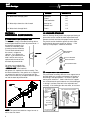
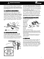
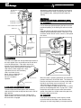
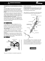
A&E
Patio Awnings
DIAGNOSTIC SERVICE MANUAL
This program will address the most common system problems associated with the A&E Patio Awnings supplied by
The Dometic Corporation. Our intent is to provide you with a guideline of checks to make, should you encounter one
of the following symptoms.
SYMPTOM
CAUSE
REFER TO
1.
Black adjustment knob will not tighten
Nutsert
Washer Stack-up
1.1
1.2
2.
Fabric leaks at the roller tube
Stitches
2.10
3.
Main support arms will not extend
Push button assembly
Adjustable arm assembly
1.3
1.4
4.
Awning has bulges or wrinkles where pull strap
rolls up
Operation
3.1
5.
Awning fabric will not roll up straight
Fabric position
Out of square
2.1
2.2
6.
Weatherguard wrinkled
Seams
Vehicle sidewall
Tek screws
Weatherguard
Out of square
2.4
4.2
2.12
2.3
2.2
7.
Fabric does not hang well
Out of square
Tube deflection
Tek screws
Seams
Vehicle sidewall
Stitches
2.2
2.6
2.12
2.4
4.2
2.10
8.
Must lift main arm(s) to open or close the awning
Stop plug
Bottom mounting brackets
1.7
1.6
9.
Awning arm(s) stay up against side of coach when
trying to open awning
Top mounting bracket
Fabric position
Operation
Travel lock
1.5
2.1
3.1
3.4
10. Awning will not roll up
Rafters
Cam
Black adjustment knob
Torsions
1.8
2.9
1.9
2.8
11. Awning will not stay in rolled down position
Cam
2.9
12. Awning billows out when traveling down the road
Cam
2.9
13. Awning stops at guard when rolling up
Rafters
Stop plug
Operation
Torsions
Awning rail
Top mounting brackets
1.8
1.7
3.2
2.8
4.3
1.5
1
Diagnostic Service Manuals
A&E
Patio Awnings
SYMPTOM
DIAGNOSTIC SERVICE MANUAL
CAUSE
REFER TO
14. Water leaks through guard
Operation
Guard
Tube deflection
3.3
2.5
2.6
15. Water drips down the side of coach
Awning rail
Rubber seal
4.1
2.7
16. Water leaks through fabric
Fabric
2.11
SECTION 1
HARD
WARE COMPONENTS
HARDW
1.1 NUTSERT OR SPECIAL NUT
The nutsert is simply a threaded fastening device
used to tighten down the black adjustment knob. If
the knob will not tighten, first
remove the secondary rafter
assembly from the hardware.
Turn the knob to determine if
the nutsert is stripped or
NUTSERT
spinning. If so, replace the
nutsert. If you cannot turn the
knob it will be necessary to
replace both the nutsert and
the black adjustment knob.
On some arm assemblies the
nutsert has been replaced with
a SPECIAL NUT
NUT. If the knob will
not tighten, first separate the rafter assembly. Turn
the knob to determine if the special nut is stripped. If
so, replace the special nut. If you cannot turn the
knob, it will be necessary to replace both the special
nut and the back adjustment knob.
SPECIAL
NUT
1.2 WASHER STACK-UP
Washer stack-up merely means the proper positioning of
the washers on the stud of the black adjustment knob.
Remove the knob and check for proper washer position.
The plastic washer should be against the main rafter,
and backed by the metal washer for stiffness. If the
stack-up is not proper it should be corrected.
SECONDARY
RAFTER
PLASTIC WASHER
METAL WASHER
ADJUSTMENT KNOB
1.3 PUSH BUTTON ASSEMBLY
The push button assembly locks the main support arm to
the adjustable arm assembly and controls the height of
the awning in the open position. To check it, open the
awning to full extension. Look inside the main support
arm, and activate the push button to see if the locking pin
is moving in and out of the hole in the adjustable arm
assembly. If the locking pin does not move, or has been
SD 66 BS RIVET
(3/16 DIA. POP
RIVET)
COMPRESSION
SPRING
LIFT HANDLE LOCK BUTTON
3/16" X 1/4"
GRIP
ALUMINUM
POP RIVET
BUTTON
LOCK
BUTTON
RETAINER
MAIN SUPPORT
ARM
NOTE
NOTE: The special nut could be a large hex nut as
well as the one shown.
2
SD 66 BS RIVET
(3/16 DIA. POP RIVET)
#8—32
HEX NUT
A&E
Patio Awnings
DIAGNOSTIC SERVICE MANUAL
broken off, the push button assembly must be replaced.
At times the lock pin of the push button assembly can
break off and jam between the push button housing and
the adjustable arm assembly, making it difficult to extend
the main support arm.
1.4 ADJUSTABLE ARM ASSEMBLY
The adjustable arm assembly allows for telescoping
height adjustment of the main support arm, and it
connects to the bottom mounting bracket to support the
weight of the awning. If the main support arm cannot be
extended freely, the adjustable arm assembly should be
checked. Remove the adjustable arm assembly and
check for nicks, burrs, bends or twists. If any deflection
is noted, the adjustable arm assembly must be replaced.
For ease of operation apply GO-EASY, a special lubricant.
LIFT
HANDLE
ARM
ASSEMBLY
ADJUSTABLE
ARM
NOTE: GO-EASY is available from your distributor.
1.5 TOP MOUNTING BRACKETS
The top mounting bracket supports the main rafter
assembly to hold the awning in the open extended
position, and allows the rafter to pivot into the “C”
channel of the main support arm. Each top mounting
bracket should be mounted directly over the awning rail
so the screws go through the “C” portion of the rail.
TOP MOUNTING BRACKET
On the Series 9000 awning the top mounting bracket
can be mounted lower when possible. If the top mounting bracket is mounted above center of the awning rail,
the aluminum guard may not cover the fabric completely
in the closed position. If this is the case, relocate the
top mounting bracket accordingly.
The top mounting brackets have slotted holes for the
mounting screws, allowing them to be adjusted side to
side. To adjust the brackets, close the awning and
sight down the main support arm and the main rafter.
The clearance on each side of the rafter should be
approximately 1/4 inch. If clearance is not appropriate,
adjust the top mounting bracket(s) as necessary.
1.6 BOTTOM MOUNTING BRACKETS
The bottom mounting brackets
are screwed to the
floor line of the
unit, and they
support the
weight of the
BOTTOM MTG.
BRACKET
awning. They
INSERT
also provide a
BOTTOM
BOTTOM
MOUNTING
quick release
MOUNTING
BRACKET
BRACKET
to set up the
SPACER
#14 X 2-1/2"
HEX. HD. SCREWS
awning in
the patio
position. If a bottom mounting
bracket settles, sags, or becomes loose it can reduce
the clearance between the top casting of the torsion
and the extension of the top mounting bracket, making
operation difficult.
Check the bottom mounting bracket for looseness or
settling, and tighten or reposition it accordingly for
proper operation.
1.7 STOP PLUG
The stop plug is a mechanical stop that supports the
main arm when opening and closing the awning. It
controls the clearance between the top casting of the
torsion to the extension of the top mounting bracket.
This clearance should be 1/4 inch to 1 inch. To adjust
the clearance, raise or lower the stop plug as needed.
On the 9000 and 9500 Series awning the clearance
should be kept to a minimum for best operation.
TOP VIEW OF MAIN SUPPORT
ARM AND RAFTER
MAIN SUPPORT ARM
RAFTER
1/4" CLEARANCE, EACH SIDE
FROM TOP TO BOTTOM OF
ARM ASSEMBLY
3
A&E
Patio Awnings
DIAGNOSTIC SERVICE MANUAL
Attempting to open the awning without first loosening
the black adjustment knobs can damage the slider of
the secondary rafter, making it difficult to open the
awning.
TOP MOUNTING
BRACKET
AWNING RAIL
SECTION 2
FABRIC R
OLLER TUBE ASSEMBL
Y (FR
TA)
ROLLER
ASSEMBLY
(FRT
CLEARANCE
EXTENSION
2.1 POSITION
For the awning to operate properly the fabric must be
positioned properly in the awning rail and on the roller
tube.
Open the awning and check the position of the fabric
between the top mounting brackets. If the fabric is not
centered, remove the tek screws, center it, and replace
the screws.
MAIN SUPPORT ARM
STOP PLUG
MAIN ARM
STOP
PLUGS
#10 LOCK NUT
3/16" DIA. HOLE
CLOSEST TO
MAIN ARM
CLEARANCE
FROM FABRIC
TO END CAP
#6 X 1/2" TEK SCREW
2"
1.8 RAFTERS
The rafters telescope from the top mounting brackets to
the main support arms to provide tension on the fabric
in the full open position. If the rafters are bent or
twisted, this will hinder the operation of the awning.
Open the awning and remove the secondary
rafter from the main support arm. Now
sight down the main and secondary
rafters and check for any
bends, twists or deflection. If
one or the other rafter is
not true it should be
MAIN RAFTER
replaced.
SECONDARY RAFTER
SLIDER
1.9 BLACK ADJUSTMENT KNOB
The black adjustment knob tightens the secondary
rafter to the main rafter to keep the fabric taut in the full
open position.
When closing the awning, the knob should not be
tightened down until after the awning is rolled up and
the travel lock is engaged.
4
AWNING RAIL
TOP
BRACKET
VINYL FABRIC
When the fabric is properly positioned, next check the
position of the fabric on the roller tube. The clearance
from the end cap of the torsion assembly to the edge of
the fabric must be the same on each end. If it is not,
adjust the fabric on the tube as necessary.
On the Elite 9000 and 9500 awning the fabric is held in
place to the weatherguard with 1/8" pop rivets. Check
the position of the fabric at each end of the weatherguard.. If the fabric has shifted, remove the pop rivets,
center the fabric and re-rivet.
2.2 SQUARE
If the fabric on the awning is out of square, it could
cause the fabric to telescope in one direction when
rolling up, or to not hang properly in the open position.
A&E
Patio Awnings
DIAGNOSTIC SERVICE MANUAL
To check fabric for square, measure from the top right
hand corner of the fabric (not the weatherguard) to the
bottom left hand corner at the poly rope. Now measure
from the top left hand corner to the bottom right hand
corner as shown below.
AWNING
RAIL
WEATHER
GUARD
FABRIC
1ST POLY
ROPE
ROLLER
TUBE
DISTANCE FROM FABRIC TO END CAP (SAME ON EACH END)
In this check, the difference of the two dimensions
should be no more than one inch. If it is more, the
fabric is out of square, and replacement would be
necessary.
2.3 WEATHERGUARD
The weatherguard is the
last 15 inches of the
awning that encloses
the fabric in the rolled
up position. It protects
the striped fabric from
the environment and
elements. The weatherguard is a heavy 17
oz. vinyl fabric.
#6 X 1/2" TEK SCREW
2"
The seams of the vinyl awning are electronically welded
together with a heat seal. The welded seams are the
strongest part of the fabric. If the fabric has wrinkles or
sags, it may be due to improper seam welding. A close
inspection may reveal the seams to be the source of the
problem. If so, fabric replacement would be needed.
Whenever wrinkles are detected in the fabric, stretching of
the weatherguard should be performed before the fabric is
condemned for bad seams. See 2.3 for stretching
instructions.
2.5 ALUMINUM GUARD
The aluminum guard on the Elite 9000 and 9500 is the
last 15 inches of the awning that encloses it in the rolled
up position, and protects the woven acrylic fiber fabric
from the environment and elements.
On 9000 awnings that have the hinge slat which fits
into the awning rail:
When the awning is fully extended, the aluminum guard
should have an arch of at least 2 inches. The arch helps
water to run off rather than between the sections of the
guard.
NOTE
NOTE: The aluminum guard is not waterproof.
SECOND SLAT
2" MIN.
TOP SLAT/HINGE ASSEMBLY
BOTTOM SLAT
ELITE 9000 SHIELD ASSEMBLY
AWNING RAIL
TOP
BRACKET
VINYL FABRIC
When the vinyl weatherguard or fabric has
excessive wrinkles, it will be necessary to stretch the
weatherguard or fabric. Open the awning and allow the
fabric to warm up. Remove one Tek screw, grasp the
weatherguard, stretch it, and resecure the screw. Repeat
this procedure for the other end, making sure to stretch
each side an equal distance, keeping the fabric centered
between the top mounting brackets.
Close and reopen the awning three times. If wrinkles are
still present, repeat the above stretching procedure. This
may have to be done 4 or 5 times before all wrinkles
disappear.
To check the aluminum guard for proper arch, open the
awning to full extension, making sure the fabric is taut.
Hold a flat edge to the bottom of the guard and measure
from the flat edge to the inside of the arch at its highest
point. If the measurement is less than 2 inches, the guard
should be replaced.
On both 9000 and 9500 awnings that DO NOT have the
slat:
hinge slat
The arch of the aluminum guard is not important as the
fabric goes under the aluminum guard and attaches the
awning to the awning rail.
2.6 ROLLER TUBE
2.4 SEAMS
5
A&E
Patio Awnings
DIAGNOSTIC SERVICE MANUAL
9000 WITH HINGE SLA
T
SLAT
E
C
D
D
D
A - VINYL STRIP
T
B - HINGE SLA
SLAT
T
C - TOP SLA
SLAT
T
D - MAIN SLA
SLAT
E-A
WNING RAIL
AWNING
VINYL STRIP "A"
D
D
INSTALL A 1/8"
POP RIVET
EACH END
HINGE SLAT "B"
TOP SLAT "C"
VIEW RH END
E
5/16" CHANNEL
BOTH ENDS
C
MAIN SLAT "D"
VIEW RH END
D
D
D
D
5/16" CHANNEL
INSTALL TOWARD
CANOPY
3/8" CHANNEL
FOR VINYL
STRIP "A"
1/4" CHANNEL
INSTALL TOWARD
AWNING RAIL
HINGE SLAT "B"
D
1/4" CHANNEL
INSTALL A 1/8"
POP RIVET
EACH END
9000 AND 9500 WITHOUT HINGE SLA
T
SLAT
6
VINYL STRIP "A"
5/16" ROD IN
AWNING RAIL
A&E
Patio Awnings
DIAGNOSTIC SERVICE MANUAL
The roller tube is a 3-1/2 inch diameter tube. It has three
symmetrical grooves to retain the poly ropes of the awning
fabric.
If the fabric appears to have more than normal sag, the
roller tube deflection must be taken into consideration.
Depending on the length of the awning, the roller tube can
deflect from one to five inches with the awning in the open
position.
Installing a tension rafter will usually remove 80 per cent of
sag and roller tube deflection. All awnings 22 feet and
longer should be installed with heavy duty hardware which
includes a center tension rafter, a center supporter, and
heavy duty adjustable arm assemblies.
If the roller tube is bent, it will bounce up and down when
opening and closing the awning. On the 9000 Series this
can cause the aluminum guard to leak, because the guard
assembly may not be tight.
provides tension on the roller tube to roll the awning up
into the travel position.
The right hand torsion end cap contains a cam assembly which prevents the awning from billowing or unrolling during travel. It also allows one-person set-up of
the awning by preventing rollback.
When difficulties are experienced in rolling the awning
up, the tension on the torsion should be checked. In
#6 MACHINE SCREW
TOP CASTING
WASHER
END CAP
WITH ASSY.
3/16" POP RIVETS
2.7 RUBBER SEAL
On the 9000 Series awning(see Section 2.5), an extruded black rubber seal is located at the awning rail of
the coach. The seal slides into the metal hinge which
connects the aluminum guard to the awning rail. This
seal is designed to prevent water from running down the
side of the coach.
To check, inspect the full length of the seal for proper
positioning, and for cuts, tears or wrinkles. If any of
these problems are found, the seal should be repaired or
replaced.
On some units it may be necessary to silicone seal the
lips of the rubber seal to the awning rail and the top slat
of the aluminum guard as shown , to prevent water from
running down the side of the RV.
TORSION SPRING/
STABILIZER ASSEMBLY
STABILIZER
HEX LOCK NUT
FABRIC
TORSION ROD
2.8 TORSION
ROLLER TUBE
SILICONE SEALANT
TOP SLAT
IDLER SLEEVE
RUBBER SEAL
most cases adding a few turns of torque to each end
will correct the problem. If all tension has been lost,
refer to the following chart and apply the specified
number of turns as indicated. This must be done with
the awning extended two feet away from the coach.
.
METAL HINGE
AWNING RAIL
9000 AWNINGS
WITH HINGE
SLAT
The torsion assembly has a wound coil spring which
7
A&E
Patio Awnings
DIAGNOSTIC SERVICE MANUAL
TORSION ASSEMBLY TORQUE SPECIFICATIONS
Number of Turns
MODEL NUMBER
Awning Length (Ft.)
8
9
10
10' 8"
11
12
13
14
15
16
16'6"
17
18
19
19'6"
20
21
22
23
24
25
5000
7000
6
6
6
6
6
6
7
7
8
8
10
10
11
11
11
12
12
12
12
8
8
8
8
9
9
10
10
12
12
13
13
13
-
7500
8000
8500
9000
9500
Grande Pavillion
8
8
8
8
8
8
9
9
10
10
12
12
12
13
13
13
13
14
14
14
14
6
6
7
7
8
8
8
9
9
See Spring Indentification Chart for No. of Turns
AWNING RAIL
TOP CASTING
RIGHT HAND SIDE
(VIEWED FROM FRONT)
AWNING RAIL
TOP CASTING
LEFT HAND SIDE
(VIEWED FROM REAR)
When winding the torsion, be sure to wind in the proper
direction.
SEVERE INJURIES CAN RESULT FROM
THE SPINNING TOP CASTING. USE VISE
GRIPS® (NEVER BARE HANDS) TO
GRASP TOP CASTING WHILE LOADING
TORSION.
Note: Rewinding must be done with the
Awning Fabric extended two feet away
from the coach.
2.9 CAM
The cam assembly locks the roller tube from turning in
8
SPRING IDENTIFICATION CHART
Standard
Wire Dia.
Heavy Duty
.120
.140
RH
Painted red cap
end and no paint
on stabilzier end.
Painted red cap
end and white
on stabilzier end.
LH
No paint on either
end.
Painted white on
cap end and no
paint on stabilizer
end.
Length
22'
23'
24'
25'
TURNS OF TENSION
14
14
14
14
8
8
8
8
one direction or the other according to which way the
cam lock lever is flipped.
To check the cam lock on the A&E awning, unlock the
main support arms. Hook the pull rod into the pull strap
and try to open the awning. Be sure the cam lock lever
is in the roll-up position. If the roller tube rotates 1/2
turn or more the cam lock must be repaired or replaced.
To check the roll-down position of the cam lock, open
the awning to full extension. Grasp the roller tube with
your hands and try to turn the tube in the direction it will
roll up. If the tube can be rotated 1/2 turn or more the
cam lock must be repaired or replaced.
2.10 STITCHES
The side hems and poly ropes of the awning are
stitched in with a sewing machine. At times the stitches
can allow water to leak through to the inside of the
roller tube. On vinyl awnings the stitches should be
sealed with seam sealer, available at sporting goods
stores. This will stop the water from running down the
inside of the roller tube. For the woven acrylic fabric of
the 9000, 9500 Series awning, Acrylife is an approved
sealant.
When sewing in the poly ropes of the fabric, if a straight
line is not followed it could cause the fabric to hang
A&E
Patio Awnings
DIAGNOSTIC SERVICE MANUAL
improperly. A close inspection of the stitching could
reveal the cause of a sag or pucker.
2.11 FABRIC
A. 9000 AND 9500
The awning fabric is woven acrylic, not vinyl. It is water
resistant but not waterproof. Once a year it should be
cleaned with Canopy-Clean and resealed to maintain its
water resistance. Acrylife is an approved sealant for the
9000, 9500 fabric. Follow the directions for application
of Canopy-Clean and Acrylife.
If the pull strap is rolled up at one end of the awning, it
can cause the fabric to telescope in that direction during
roll-up, and create a bulge or wrinkles at that end. This
could cause the awning arm to stay against the side of
the coach when trying to open.
3.2 CLOSING
NOTE: Avoid touching the underside of the
awning fabric when it is wet, as this breaks
the surface tension of the water causing it
to seep through.
PULL STRAP
B. 8500 AND GRANDE PAVILLION
The awning fabric is vinyl. It is waterproof. Once a year it
should be cleaned with Canopy-Clean and treated with
Vinyl Formula 201 to protect and extend the life of the
fabric. Follow the directions for application for CanopyClean, and Vinyl Formula 201. Contact your distributor
for these products.
2.12 TEK SCREWS
The Tek screws are the two screws installed through
the awning rail of the coach. They keep the aluminum
guard from shifting in the awning rail. On vinyl and
some acrylic awnings (see Sec. 2.5) they keep the
fabric from shrinking with age. If one Tek screw is
missing, the fabric will pull toward the remaining Tek
screw causing the fabric to wrinkle.
#6 X 1/2" TEK SCREW
2"
On the 9000 and 9500 Series, when rolling up the
awning, the roller tube assembly should not be slowed
down before reaching the aluminum guard. This could
cause the roller tube to stall at the guard.
3.3 TAUTNESS
On 9000 Sereis awnings that utilize a hinge slat (see
Sec. 2.5): To minimize water leakage through the
aluminum guard, the fabric must be taut when the
awning is extended. This will keep the sections of the
aluminum guard tight against each other. Before
tightening the black adjustment knob, be sure to apply
enough downward force on the main support arm to pull
the fabric taut.
3.4 TRAVEL LOCK
The travel lock must be fully released before trying to
open the awning.
SECTION 4
AWNING RAIL
MAIN SUPPORT ARM
TOP
BRACKET
FABRIC
UNLOCK
TRAVEL
LATCH
MAIN SUPPORT ARM
LOCK
TRAVEL
LATCH
SECTION 3
OPERA
TION
OPERATION
3.1 PULL STRAP
When closing the awning the pull strap must be rolled
up at an angle from the center of the roller tube. This
will keep the awning from telescoping forward or
rearward, and will prevent a bulge from forming in the
area where the strap is rolled up.
9
A&E
Patio Awnings
AWNING RAIL
4.1 LEAKAGE
When water drips down the side of the coach, the seal
between the coach and the awning rail must be
checked. If improper seal is detected, reseal the
awning rail.
4.2 STRAIGHT
Before condemning the fabric for sags or wrinkles, the
awning rail should be checked. Open the awning and
sight down the rail to see if the rail or sidewall varies up,
down, inward or outward. This must be taken into
consideration when checking a fabric.
DIAGNOSTIC SERVICE MANUAL
There are three types of awning rail used in the RV
industry. Of these, type A and B (see below) are
acceptable for use on the 9000 Series awning that
utilizes a hinge slat (see Sec.2.5) . Type C should never
be used on the 9000 Series that utilizes a hinge slat
(see Sec. 2.5) as it could cause a binding problem on
the aluminum guard assembly, but it is acceptable on
the vinyl awnings.
A
B
C
OPENING
OUTWARD
OPENING
UPWARD
OPENING
DOWNWARD
4.3 TYPE
10
!"
!
(
#$% &
&
'
'