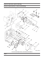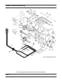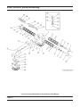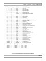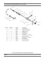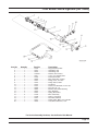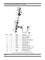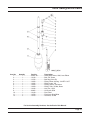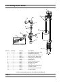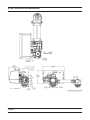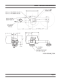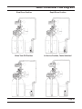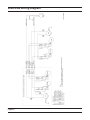
1
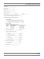
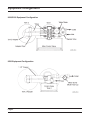
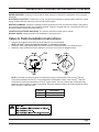
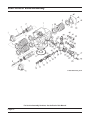
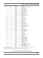
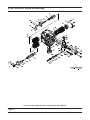
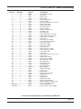
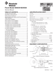
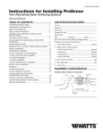
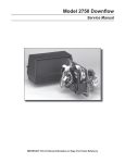
Model 9000/9100/9500
Service Manual
IMPORTANT: Fill in Pertinent Information on Page 3 for Future Reference
Table of Contents
Job Specification Sheet ......................................................................................................................................... 3
Equipment Configuration ....................................................................................................................................... 4
General and Commercial Installation Checklist ..................................................................................................... 5
Valve to Tank Installation Instructions .................................................................................................................... 7
Regeneration Cycle Program Setting Procedure .................................................................................................. 8
Time Brine Refill and Meter Setting Procedure ..................................................................................................... 9
9000/9100/9500 Electro Mechanical Timer Assembly ......................................................................................... 12
Power Head Assembly ........................................................................................................................................ 14
9000 Control Valve Assembly .............................................................................................................................. 16
9100 Control Valve Assembly .............................................................................................................................. 18
9500 Control Valve Assembly .............................................................................................................................. 20
1600 Brine Valve System (for 9500) .................................................................................................................... 22
1700 Brine Valve System (for 9500) .................................................................................................................... 23
9000 Second Tank Assembly .............................................................................................................................. 24
9100 Second Tank Assembly .............................................................................................................................. 25
9500 Second Tank Assembly .............................................................................................................................. 26
3/4” Meter Assembly ............................................................................................................................................ 27
1” Meter Assembly ............................................................................................................................................... 28
1 1/2” Meter Assembly ......................................................................................................................................... 29
9000/9100 Bypass Valve Assembly..................................................................................................................... 30
Bypass Valve Assembly....................................................................................................................................... 31
1710 Brine Valve System (for 9500) .................................................................................................................... 32
2300 Safety Brine Valve ...................................................................................................................................... 33
2310 Safety Brine Valve ...................................................................................................................................... 34
2350 Safety Brine Valve ...................................................................................................................................... 35
Troubleshooting ................................................................................................................................................... 36
General Hints for Meter Control........................................................................................................................... 37
9000/9100/9500 Meter Flow Data ....................................................................................................................... 38
9000/9100 Injector Flow Data (1600 Series Injectors) ........................................................................................ 39
9500 Injector Flow Data (1600 & 1700 Series Injectors) ..................................................................................... 40
9000 Control Dimensions .................................................................................................................................... 41
9100 Control Dimensions .................................................................................................................................... 42
9500 Control Dimensions .................................................................................................................................... 43
Water Conditioner Flow Diagrams ....................................................................................................................... 44
9000/9500 Wiring Diagram .................................................................................................................................. 46
Service Assemblies ............................................................................................................................................. 47
IMPORTANT PLEASE READ:
•
The information, specifications and illustrations in this manual are based on the latest information available at the time of
printing. The manufacturer reserves the right to make changes at any time without notice.
•
This manual is intended as a guide for service of the valve only. System installation requires information from a number of
suppliers not known at the time of manufacture. This product should be installed by a plumbing professional.
•
This unit is designed to be installed on potable water systems only.
•
This product must be installed in compliance with all state and municipal plumbing and electrical codes. Permits may be
required at the time of installation.
•
If daytime operating pressure exceeds 80 psi, nighttime pressures may exceed pressure limits. A pressure reducing valve must
be installed.
•
Do not install the unit where temperatures may drop below 32°F (0°C) or above 125°F (52°C).
•
Do not place the unit in direct sunlight. Black units will absorb radiant heat increasing internal temperatures.
•
Do not strike the valve or any of the components.
•
Warranty of this product extends to manufacturing defects. Misapplication of this product may result in failure to properly
condition water, or damage to product.
•
A prefilter should be used on installations in which free solids are present.
•
In some applications local municipalities treat water with Chloramines. High Chloramine levels may damage valve components.
•
Correct and constant voltage must be supplied to the control valve to maintain proper function.
Job Specification Sheet
Job Number: __________________
Model Number: ________________
Water Test: ___________________
Capacity Per Unit: ______________
Mineral Tank Size: ___________ Diameter: ___________ Height: __________
Brine Tank Size & Salt Setting per Regeneration: __________
9000/9100/9500 Control Valve Specifications:
1. Type of Timer:
A. 82 minute available regeneration time, 1/15 RPM
B. 164 minute available regeneration time, 1/30 RPM
2. Type of Meter:
Mechanical Valves (Gallon Settings)
Meter
Standard Range
3/4”
125 - 2,125
1”
310 - 5,270
1-1/2”
625 - 10,625
Extended Range
625 - 10,625
1,150 - 26,350
3,125 - 53,125
3. Timer Gallon Setting: _______________Gallons
4. Regeneration Program Setting:
A. Backwash: ____________________ Minutes
B. Brine and Slow Rinse: ___________ Minutes
C. Rapid Rinse: __________________ Minutes
D. Brine Tank Refill: _______________ Minutes
5. Drain Line Flow Control: ____________ gpm
6. Brine Refill Rate: __________________ gpm
7. Injector Size: _____________________
Page 3
Equipment Configuration
9000/9100 Equipment Configuration
9500 Equipment Configuration
Page 4
General and Commercial Installation Checklist
1. Place the softener tank where you want to install the unit.
NOTE: Be sure the tank is level and on a firm base.
2. During cold weather it is recommended that the installer warm the valve to room temperature before
operating.
3. Perform all plumbing according to local plumbing codes.
— Use a 1/2” minimum pipe size for the drain.
— Use a 3/4” drain line for backwash flow rates that exceed 7 gpm or length that exceeds 20’ (6 m).
4. Both tanks must be the same height and diameter and filled with equal amounts of media.
5. The distributor tube must be flush with the top of each tank. Cut if necessary. Use only non-aerosol silicone
lubricant.
6. Lubricate the distributor o-ring seal and tank o-ring seal. Place the main control valve on one tank and the
tank adapter on the second tank.
NOTE: If required, solder copper tubing for tank interconnection before assembling on the main control valve
and tank adapter. Maintain a minimum of 1” distance between tanks on final assembly.
7. Solder joints near the drain must be done before connecting the Drain Line Flow Control fitting (DLFC).
Leave at least 6” (152 mm) between the DLFC and solder joints when soldering pipes that are connected on
the DLFC. Failure to do this could cause interior damage to DLFC.
8. Use only Teflon tape on the drain fitting.
9. Be sure the floor under the salt storage tank is clean and level.
10. Place approximately 1” (25 mm) of water above the grid plate. If a grid is not utilized, fill to the top of the air
check in the salt tank. Do not add salt to the brine tank at this time.
11. On units with a bypass, place in Bypass position.
— Turn on the main water supply.
— Open a cold soft water tap nearby and let water run a few minutes or until the system is free of foreign
material (usually solder) resulting from the installation. Close the water tap when water runs clean.
12. Place the bypass In Service position and let water flow into the mineral tank. When water flow stops, slowly
open a cold water tap nearby and let water run until air is purged from the unit. Then close tap.
Electrical
13. Make all electrical connections according to codes. Plug the valve into an approved power source. Do not
insert meter cable into the meter yet.
14. Tank one has control valve and tank two has adapter.
15. Look on the right side of the control valve, it has indicators showing which position the control valve is in
during Regeneration and which tank is In Service.
NOTE: Make sure the meter cable is not inserted in the meter dome. Swing the timer out to expose the
program wheel (to swing timer out) grab onto the lower right corner of timer face and pull outward.
Page 5
General and Commercial Installation Checklist
Control Valve Position Indicators
Timer
Program Wheel
16. Cycle timer into backwash position. Turn manual knob so that the micro switch rides on the first set of pins.
— In this position the tanks switch (lower piston) and the control valve moves to the backwash position
(upper piston).
— Wait until the positioning of upper and lower pistons stops before advancing the timer further. If advanced
too fast the control will not home into the In Service position (it will not advance to any other position). To
correct this, rotate the manual knob back to In Service and start again into backwash.
NOTE: Once valve positions itself into the backwash cycle, the homing circuit locks in.
17. With all the air backwashed, slowly cycle the timer to the brine position; rapid rinse; and brine tank refill.
Wait for the control drive motor to position itself in each cycle and stop, before advancing on to the next
position.
18. Once back in the In Service position, cycle the control valve again into the backwash position. The tanks
switch again, and air head backwashes out of the other tank. Cycle the control back to the In Service position.
Leave the timer in the open position. DO NOT insert meter cable yet.
NOTE: Two motors are available.
1/15 RPM has 82 minute regeneration time.
1/30 RPM has 164 minute regeneration time.
Page 6
General and Commercial Installation Checklist
WATER PRESSURE: A minimum of 25 pounds of water pressure is required for regeneration valve to operate
effectively.
ELECTRICAL FACILITIES: A continuous 115 volt, 60 Hertz current supply is required. Make certain the current
supply is always hot and cannot be turned off with another switch.
EXISTING PLUMBING: Condition of existing plumbing should be free from lime and iron buildup. Piping that is
built up heavily with lime and/or iron should be replaced. If piping is clogged with iron, a separate iron filter unit
should be installed ahead of the water softener.
LOCATION OF SOFTENER AND DRAIN: The softener should be located close to a drain.
BY-PASS VALVES: Always provide for the installation of a by-pass valve.
Valve to Tank Installation Instructions
1. Spin the valve onto the tank, ensuring the threads are not cross-threaded.
NOTE: All Fleck® valves are right-hand threads, or clockwise, to install
2. Rotate the valve freely without using force until it comes to a stop (this position is considered zero).
3. Rotate the valve clockwise from zero, between ¼ turn and ½ turn (see the diagram below).
NOTE: If lubricant is required, a silicone compound is strongly recommended. Dow Corning® Silicone
Compound (available from Fleck®), is recommended for best possible results. Dow Corning® 7 Release
Compound is used in the manufacture of Fleck® control valves. The use of other types of lubricants may
attack the control’s plastic or rubber components. Petroleum-based lubricants can cause swelling in rubber
parts, including o-rings and seals.
Part No.
16174
16586-8
Description
Silicone, 2 oz Tube
Silicone, Dow #7 8 LB
Page 7
Regeneration Cycle Program Setting Procedure
Setting the Regeneration Cycle Program
The Regeneration cycle program on the water conditioner is preset at the factory. However, portions of the cycle
or program time may be lengthened or shortened for local conditions or system design.
1. Expose cycle program wheel by grasping timer in lower right hand corner and pulling. This releases snap
retainer and swings timer to the left
NOTE: Meter cable must be removed from meter dome before opening timer.
2. Remove the program wheel by grasping program wheel and squeezing protruding lugs towards center.
Lift program wheel off timer.
— Switch arms may require movement to facilitate removal.
3. Return timer to closed position by engaging snap retainer in back plate.
— Make certain all electrical wires locate above snap retainer post.
Changing Length of the Backwash Time
Looking at the numbered side of the program wheel, the group of pins starting at zero determines the length of
time the unit backwashes.
Example: If there are six pins in this section, the time of backwash is 12 minutes (2 minutes per pin). To
change the length of backwash time, add or remove pins as required.
— The number of pins multiplied by two equals minutes of backwash.
Changing Length of Brine and Rinse Time
The group of holes between the last pin in the backwash section and the second group of pins determines the
length of time that a unit will brine and rinse (2 minutes per hole).
To change the length of brine and rinse time, add or remove pins in the rapid rinse group of pins to increase or
decrease the number of holes in the brine and rinse section.
— The number of holes multiplied by two equals minutes of brine and rinse.
Changing Length Of Rapid Rinse
The second group of pins on the program wheel determines the length of time the water conditioner rapid rinses
(2 minutes per pin). To change the length of rapid rinse time, add or remove pins at the higher numbered end of
this section as required.
— The number of pins multiplied by two equals minutes of rapid rinse.
NOTE: Program wheels with 0–82 minute cycle times, use one minute per pin or hole to set Regeneration
times. The layout of pins and holes on the program wheel follow the same procedure as on this page.
Changing Length of Brine Tank Refill Time
The second group of holes on the program wheel determines the length of time the water conditioner refills the
brine tank (2 minutes per hole).
To change the length of refill time, move the two pins at the end of the second group of holes as required.
The Regeneration cycle is complete when the two pin set at end of the brine tank refill section trips the outer
micro-switch. The program wheel, however, continues to rotate until the inner micro-switch drops into the notch on
the program wheel.
Programming
1. The control valve is set at the factory for backwash; brine and slow rinse; rapid rinse and brine tank fill times.
Change any of these times by repositioning the pins and holes or adding more pins.
NOTE: Two speed timer motors are available
1/15 RPM has 82 minute Regeneration Time and each pin or hole equals one minute.
1/30 RPM has 164 minute Regeneration Time and each pin or hole equals two minutes.
Page 8
Time Brine Refill and Meter Setting Procedure
2. The control valve has a separate brine tank fill cycle.
— Calculate the desired salt setting using the brine line flow control rate of refill (in gpm) multiplied by the
timer setting. Then, using one gallon of fresh water dissolving approximately 3 lbs salt, calculate the
refill time.
Example: A desired 30 lbs salt setting:
The unit has a 1.0 gpm refill rate so a 10 gallon fill is required.
10 gallons x 3 lbs/gals = 30 lbs salt
Set the timer refill section at 10 minutes.
10 minutes x 1.0 gpm = 10 gallon fill
NOTE: There must always be two pins at the end of a refill time to stop the fill cycle. With the Regeneration
times set, place timer back to its original position, making sure the lower right hand corner snaps back into the
backplate and the meter cable slides through the backplate and does not bind.
3. Setting the gallon wheel.
Knowing the amount of resin in each tank and the salt setting per Regeneration, calculate the gallons available,
using the following capacities as a guide:
(capacity per ft3 x ft3 of resin per tank) = gallons available
compensated hardness of H2O
NOTE: Based on tank size:
More resin increases capacity, less resin decreases capacity.
More salt increases capacity, less salt decreases capacity.
Example:
Tank Diameter
Compensated Hardness
ft3 Resin (based on flow rate)
lbs of Salt
Capacity per ft3
=
=
=
=
=
16”
35 grains per gallon (tested sample)
4
8
24,000
(24,000 x 4 ft3 of resin per tank) = 2,740 gallons available before regeneration
35 grains
DO NOT SET THIS FIGURE - GO TO STEP 4
— Because the control valve regenerates with soft water from the other tank, subtract the water used for
regeneration. Take each regeneration cycle and calculate the water used.
Example: Unit is set for a 16” diameter tank with 4 ft3 of resin and salted at 8 lbs. per ft3, 7 gpm backwash,
#3 injector, 1.0 gpm brine refill, and 60 psi and timer set for 10 min. backwash, 60 min. brine and rinse,
10 min. rapid rinse, 10 min. brine tank fill.
Backwash
Brine and Rinse
Rapid Rinse
Brine Tank Fill
10 minutes x 7.0 gpm =
60 minutes x 1.0 gpm =
10 minutes x 7.0 gpm =
10 minutes x 1.0 gpm =
Total Regeneration Water =
70.0 gallons
60.0 gallons
70.0 gallons
10.0 gallons
210.0 gallons
With the 2740 gallons available calculated in Step 3, subtract the Regeneration water used from the total
water available.
2740 gallons available - 210 gallons used = 2530 gallons
(in Regeneration, Step 4)
Page 9
Time Brine Refill and Meter Setting Procedure
4. Set meter wheel at approximately 2530 gallons. Lift the inner dial of the meter program wheel so that you can
rotate it freely. Position the white dot opposite the 2530 gallon setting.
NOTE: There is a slight delay between the time the meter zeros out and the cycle starts. Units using the:
1/15 RPM motor, 82 minute Regeneration Time has a 9 minute delay
1/30 RPM motor, 180 minute Regeneration Time has an 18 minute delay.
NOTE: This delay period is not critical on residential equipment. However, take this factor into consideration
for commercial applications by subtracting continuous flows for 9 minutes or 18 minutes from water available.
5. Insert meter cable into meter.
6. Check bypass.
7. Plug in unit.
Page 10
Notes
Page 11
9000/9100/9500 (3200 Series)
Electro Mechanical Timer Assembly
For Service Assembly Numbers, See the Back of this Manual
Page 12
9000/9100/9500 (3200 Series)
Electro Mechanical Timer Assembly
Item No.
Quantity
Part No.
Description
1................... 1 .................... 13870-03 .................Housing, Timer, 9000
2................... 1 .................... 17870 ......................Label, Indicator, 9000 Timer
3................... 1 .................... 15465 ......................Label, Caution
4................... 1 .................... 16930 ......................Label, Instruction
5................... 1 .................... 15227 ......................Plate, Clutch, Actuator
6................... 1 .................... 10300 ......................Screw, Slot Hex Wsh, 18-8 x 3/8
7................... 1 .................... 17513 ......................Clip, Spring
8................... 1 .................... 15407 ......................Washer, Plain, #4
9................... 1 .................... 15228 ......................Spring, Return
10................. 1 .................... 16270-10 .................Program Wheel Assy, 9000 3/4
16270-50 .................Program Wheel Assy, 9000/9500
16270-30 .................Program Wheel Assy, 9000, 1” Std
16270-40 .................Program Wheel Assy, 9000, 1” Ext
16270-50 .................Program Wheel Assy, 9000/9500
16270-60 .................Program Wheel Assy, 9500
11 ................. 1 .................... 13806 ......................Retainer, Program Wheel
12................. 1 .................... 13748 ......................Screw, Flt Hd St, 6-20 x 1/2
13................. 2 .................... 11999 ......................Label, Button
14................. 1 .................... 15223 ......................Actuator, Cycle
15................. 1 .................... 13886 ......................Know, 3200
16................. 4 .................... 13296 ......................Screw, Hex Wsh, 6-20 x 1/2
17................. 1 .................... 17724 ......................Program Wheel, Pinion Drive
18................. 1 .................... 17723 ......................Clutch, Drive Pinion
19................. 1 .................... 14276 ......................Spring, Meter Clutch
20................. 1 .................... 14253 ......................Retainer, Clutch Spring
21................. 3 .................... 14087 ......................Insulator
22................. 1 .................... 15314 ......................Switch, Micro, Modified
23................. 1 .................... 15320 ......................Switch, Micro, Timer
24................. 2 .................... 11413 ......................Screw, Pan Hd Mach, 4-40 x 1 1/8
25................. 1 .................... 13018 ......................Pinion, Idler
26................. 1 .................... 18563 ......................Spring, Idler Shaft
27................. 1 .................... 13017 ......................Gear, Idler
28................. 1 .................... 13164 ......................Gear, Drive
29................. 1 .................... 13887 ......................Plate, Motor Mounting
30................. 1 .................... 18743 ......................Motor, 120V, 60 Hz 1/30 RPM, 5600
18824-1 ...................Motor, 230V, 50 Hz 1/30 RPM
19170 ......................Motor, 120V 60 Hz 1/15 RPM
18825 ......................Motor, 230V, 50 Hz 1/15 RPM Mallory
31................. 2 .................... 13278 ......................Screw, Phil Hd Mach, 6-32 x 1/8 Steel Zinc
32................. 1 .................... 14265 ......................Clip, Spring
33................. 1 .................... 15055 ......................Timer, Main Drive Gear
34................. 1 .................... 19210-02 .................Program Wheel Assy, 9000 1/15
19210-05 .................Program Wheel Assy, 9000/3230
35................. 23 .................. 15493 ......................Pin, Spring, 1/16 x 5/8 SS
36................. 1 .................... 15203 ......................Harness, 9000/9500, Timer
37................. 2 .................... 40422 ......................Nut, Wire, Tan
Not Shown ... 1 .................... 60320-02 .................Switch Kit, 3200/9000 Timer Auxiliary
For Service Assembly Numbers, See the Back of this Manual
Page 13
Power Head Assembly
For Service Assembly Numbers, See the Back of this Manual
Page 14
Power Head Assembly
Item No.
Quantity
Part No.
Description
1 .......................2 ........................ 18728 ............................Nut, Tinnerman, U Type, 8-32
2 .......................1 ........................ 11838 ............................Power Cord, 6’ Fleck
11839 ............................Power Cord, 12’ Fleck
40084-12 .......................Power Cord, 12’ U.S., Round, 120V Sys 5, 6, 7 &
2900/3150/3900 #4
11545-01 .......................Power Cord Assy, 4’ Black, Euro w/Terminals
14678 ............................Power Cord, U.S., 220/60
19303-01 .......................Power Cord Assy, Australian w/Terminals
40085-12 .......................Power Cord, 12’ US, Round, 240V
19674 ............................Transformer, 24V, 9.6VA Residential Valves
41475 ............................Transformer, 24V, 9.6VA, European
3 .......................1 ........................ 15202 ............................Harness, 9000/9500, Drive
14822 ............................Harness, 2900
40041-06 .......................Harness, Low V, 9000/9500
4 .......................1 ........................ 15134 ............................Gear Assy, Drive, 1/2” Stroke 9000/9500
5 .......................1 ........................ 15135 ............................Gear, Drive, 9000
6 .......................1 ........................ 14896 ............................Wheel, Geneva
7 .......................2 ........................ 40422 ............................Nut, Wire, Tan
8 .......................2 ........................ 19367 ............................Screw, Designer Cover, Thumb 8-32 Blank UV Stable Material
9 .......................1 ........................ 15175 ............................Label, Shaft Position
10 .....................2 ........................ 14917 ............................Ring, Retaining
11 .....................1 ........................ 15199 ............................Plate, Ground, 9000/9500
12 .....................1 ........................ 14430 ............................Screw, Hex Wsh St, 6 x 1/4 Type “B”
13 .....................2 ........................ 19160 ............................Screw, Phil Pan, Thread 6-32 x 3/8 Type 23 Zinc
14 .....................1 ........................ 18737 ............................Motor, 24V, 50/60 Hz, 1 RPM
18738 ............................Motor, 120V, 50/60 Hz 1 RPM
18739 ............................Motor, 220V, 50/60 Hz 1 RPM
15 .....................1 ........................ 15131 ............................Backplate, 9000
17784-05 .......................Panel, Control, 9000/9500 ET
16 .....................2 ........................ 15172 ............................Screw, Flt Hd Mach, 4-40 x 1 3/8 Steel Zinc Plate
17 .....................2 ........................ 10340 ............................Washer, Lock #4, Zinc
18 ................................................ 10218 ............................Switch, Micro
19 .....................1 ........................ 10339 ............................Nut, Hex, 4-40 Zinc Plated
20 .....................1 ........................ 15331 ............................Screw, Hex Wsh Mach, 10-24 x 3/4 410 S.S.
21 .....................2 ........................ 15133 ............................Gear Assy, Drive, 3/4” Stroke
22 .....................1 ........................ 13547 ............................Strain Relief, Flat Cord Heyco #30-1
23 .....................1 ........................ 15810 ............................Ring, Retaining
24 .....................1 ........................ 15132 ............................Cam, Triple
17331 ............................Cam, 9500
17765 ............................Cam Assy, Aux Switch, 9500
25 .....................1 ........................ 15368 ............................Tube, Cable Guide, 2-Tank
17337 ............................Tube, Cable Guide, 9500
26 .....................2 ........................ 15372 ............................Washer, Thrust, 3/8
27 .....................1 ........................ 15216 ............................Meter Cable Assy, 15.25”
15425 ............................Meter Cable, 13.25”
17744 ............................Meter Cable Assy, 20.75” 1 1/2” Std
19121-01 .......................Meter Cable Assy, SE, Paddle 6600/6700
19121-05 .......................Meter Cable Assy, ET, 28” 2750/3150 Systemax 4-6
19791-01 .......................Meter Cable Assy, Turbine/SE
28 .....................2 ........................ 15692 ............................Washer, Plain, 3/8”
29 .....................1 ........................ 16433 ............................Switch, Miniature
30 .....................1 ........................ 10302 ............................Insulator, Limit Switch
31 .....................2 ........................ 15173 ............................Screw, Slot Rd Hd Mach, 5-20 x 3/8
Not Shown
1 ........................ 60232-110 .....................Cover, Designer, 1 Pc Black
1 ........................ 60232-112 .....................Cover, Designer, 1 Pc Black w/Left Window
1 ........................ 60320-09 .......................Switch Assy, 9000, Drive Cam
1 ........................ 60320-10 .......................Switch Assy, 9500, Drive Cam
For Service Assembly Numbers, See the Back of this Manual
Page 15
9000 Control Valve Assembly
For Service Assembly Numbers, See the Back of this Manual
Page 16
9000 Control Valve Assembly
Item No.
Quantity
Part No.
Description
1 ........................1 ..........................14861-01 ........................ Valve Body, 9000, Machined w/O-ring
40688.............................. Valve Body, 9100
2 ........................1 ..........................14914.............................. Piston, 9000, Upper
3 ........................2 ..........................14309.............................. Retainer, Piston Rod
16590.............................. Retainer, Piston Rod
4 ........................1 ..........................14919.............................. Rod, Piston, Upper
5 ........................2 ..........................13446.............................. End Plug Assy, White
13446-01 ........................ End Plug Assy, White, HW
6 ........................12 ........................14241.............................. Spacer, 5600
14241-01 ........................ Spacer, Hot Water
7 ........................16 ........................13242.............................. Seal, 5600
18759.............................. Seal, 5600 Low Drive Force
8 ........................1 ..........................14920.............................. Rod, Piston, Lower, 9000
9 ........................1 ..........................14905.............................. Piston, 9000
10 ......................1 ..........................11710 .............................. O-ring, -215
11.......................1 ..........................12281.............................. O-ring, -338
12 ......................1 ..........................11981-01......................... Ring, Retaining
13 ......................1 ..........................16098.............................. Washer, Nylon Brine
14 ......................1 ..........................11973 .............................. Spring, Brine Valve
15 ......................1 ..........................13165.............................. Cap, Brine Valve
16 ......................3 ..........................13302.............................. O-ring, -014
17 ......................1 ..........................12550.............................. Quad Ring, -009
18 ......................1 ..........................13167.............................. Spacer, Brine Valve
19 ......................1 ..........................14925.............................. Brine Valve Stem, 9000
20 ......................1 ..........................12626.............................. Seat, Brine Valve
21 ......................1 ..........................15215.............................. Body, Injector, 9000
22 ......................1 ..........................10914-X .......................... Injector Throat - Specify Size
23 ......................1 ..........................10913-X .......................... Injector Nozzle - Specify Size
10225-X .......................... Injector Nozzle, SS
24 ......................1 ..........................13303.............................. O-ring, -021
25 ......................1 ..........................13166.............................. Cap, Injector, 5600
26 ......................1 ..........................16595.............................. Spacer, 9000
27 ......................1 ..........................13387.............................. Screw, Hex Hd Mach, 10-24 x 1 3/4
28 ......................1 ..........................13361.............................. Spacer, 4650/9000
29 ......................2 ..........................13301.............................. O-ring, -011, Injector
30 ......................1 ..........................13497.............................. Disperser, Air, 5600
31 ......................1 ..........................15348.............................. O-ring, -563
32 ......................1 ..........................10227.............................. Screen, Injector
34 ......................1 ..........................13244.............................. Adapter, BLFC
35 ......................1 .................................................................. Button, BLFC - Specify Size
36 ......................1 ..........................13245.............................. Retainer, BLFC
12977.............................. O-ring, -015
38 ......................1 .................................................................. Button, DLFC - Specify Size
39 ......................1 ..........................13173.............................. Retainer, DLFC Button
40 ......................1 ..........................10332.............................. Fitting, Insert, 3/8
15415* ............................ Fitting, Insert, 1/2” Tube
41 ......................1 ..........................10330.............................. Fitting, Sleeve, 3/8 Celcon
16124* ............................ Fitting, Sleeve, Delrin
42 ......................1 ..........................10329.............................. Fitting, Tube, 3/8 Nut, Brass
16123* ............................ Nut, Brass
43 ......................1 ..........................14928.............................. Plug, End Stub, 9000
44 ......................1 ..........................14906.............................. Plate, End, 9000
45 ......................4 ..........................15137.............................. Screw, Hex Wsh Mach 10-24 x 3/8
47 ......................1 ..........................13387.............................. Screw, Hex Hd Mach, 10-24 x 1 3/4
13361.............................. Spacer, 4650/9000
48 ......................1 ..........................13315.............................. Screw, Hex Wsh Hd, 10-24 x 1 3/16
Not Shown .........1 ..........................16140.............................. Fitting, 1/2T x 1/4 NPT
NOTE: For Hot Water delete items 41 & 42 and use 18698 (Nut, 3/8 Tube, w/Sleeve) and 15414 (Nut, 2900, w/Sleeve)
*These parts are used with #4 injector and 2 GPM or larger BLFC (Items 34, 35, and 36 are not used).
For Service Assembly Numbers, See the Back of this Manual
Page 17
9100 Control Valve Assembly
For Service Assembly Numbers, See the Back of this Manual
Page 18
9100 Control Valve Assembly
Item No.
Quantity
Part No.
Description
1...................... 1 ........................40688 .......................... Valve Body Assy, 9100
2...................... 16 ......................13242 .......................... Seal, 5600
3...................... 12 ......................14241 .......................... Spacer, 5600
4...................... 1 ........................16595 .......................... Spacer, 9000
5...................... 1 ........................14928 .......................... Plug, End Stub, 9000
6...................... 1 ........................14906 .......................... Plate, End, 9000
7...................... 4 ........................15137 .......................... Screw, Hex Wsh Mach, 10-24 x 3/8
8...................... 1 ........................14914 .......................... Piston, 9000, Upper
9...................... 2 ........................14309 .......................... Retainer, Piston Rod
10.................... 1 ........................14919 .......................... Rod, Piston, Upper
11 .................... 2 ........................13243 .......................... Plug, End, 5600
12.................... 2 ........................13008 .......................... Retainer, End Plug Seal
13.................... 2 ........................10209 .......................... Quad Ring, -010
14.................... 1 ........................14921 .......................... Link, Piston Rod
15.................... 2 ........................11335........................... Screw, Slot Phil Hd, 4-40 x 3/16
16.................... 2 ........................17020 .......................... Screw, Slot Ind Hex, 6-20 x 3/8
17.................... 2 ........................13363 .......................... Washer, Plain, .145 ID SS
18.................... 1 ........................14905 .......................... Piston, 9000
19.................... 1 ........................14920 .......................... Rod, Piston, Lower, 9000
20.................... 1 ........................15019 .......................... Link, Piston Rod, 9000/9500
21.................... 1 ........................41500 .......................... O-ring, Drain, 9100
22.................... 1 ........................15215 .......................... Body, Injector, 9000
23.................... 2 ........................13301 .......................... O-ring, -011, Injector
24.................... 1 ........................10227 .......................... Screen, Injector
25.................... 1 ........................10913-1 ....................... Nozzle, Injector, #1, White
26.................... 1 ........................10914-1 ....................... Throat, Injector, #1, White
27.................... 1 ........................13166 .......................... Cap, Injector, 5600
28.................... 1 ........................13303 .......................... O-ring, -021
29.................... 2 ........................13387 .......................... Screw, Hex Hd Wash, 10-24 x 1 3/4
30.................... 1 ........................15348 .......................... O-ring, -563
31.................... 1 ........................13173 .......................... Retainer, DLFC Button
32.................... 1 ........................12085 .......................... Washer, Flow, 1.2 GPM
33.................... 1 ........................14925 .......................... Brine Valve Stem, 9000
34.................... 1 ........................12626 .......................... Seat, Brine Valve
35.................... 1 ........................13167 .......................... Spacer, Brine Valve
36.................... 1 ........................13165 .......................... Cap, Brine Valve
37.................... 1 ........................11973........................... Spring, Brine Valve
38.................... 1 ........................11981-01 ..................... Ring, Retaining
39.................... 1 ........................16098 .......................... Washer, Nylon Brine
40.................... 1 ........................12977 .......................... O-ring, -015
41.................... 1 ........................13245 .......................... Retainer, BLFC
42.................... 1 ........................129095 ........................ Washer, Flow, .50 GPM
43.................... 1 ........................12550 .......................... Quad Ring, -009
44.................... 2 ........................13302 .......................... O-ring, -014
45.................... 1 ........................13244 .......................... Adapter, BLFC
46.................... 1 ........................13497 .......................... Disperser, Air, 5600
47.................... 1 ........................13361 .......................... Spacer, 4650/9000/WCC
48.................... 1 ........................40538 .......................... Retainer, 32mm, O-ring Dist, 7000
49.................... 1 ........................61419 .......................... Kit, 1.05” Distributor, Adapter
Not Shown ...... 1 ........................13333 .......................... Label, Injector, Blank
Not Shown ...... 1 ........................10759 .......................... Label, .5 GPM, 1.5 LBS Salt/Min
For Service Assembly Numbers, See the Back of this Manual
Page 19
9500 Control Valve Assembly
For Service Assembly Numbers, See the Back of this Manual
Page 20
9500 Control Valve Assembly
Item No.
Quantity
Part No.
Description
1...................... 1 ........................16919-01 ..................... Valve Body, 9500 Machd
2...................... 16 ......................16101 .......................... Seal, 2850
3...................... 12 ......................16638 .......................... Spacer, 9500/2850
4...................... 1 ........................17110........................... Piston, 9500, Upper
5...................... 2 ........................14309 .......................... Retainer, Piston Rod
6...................... 1 ........................16957 .......................... Rod, Piston, 9500
7...................... 2 ........................17212 .......................... End Plug Assy, White
17212-01 ..................... End Plug Assy, White, HW, 560CD
8...................... 1 ........................17111 ........................... Piston, 9500, Lower
9...................... 1 ........................16956 .......................... Rod, Piston, Lower
10.................... 1 ........................17092 .......................... Spacer, Disc, 9500
11 .................... 1 ........................16955 .......................... Plug, End, 9500
12.................... 3 ........................16394 .......................... O-Ring -029
13.................... 1 ........................14906 .......................... Plate, End, 9000
14.................... 4 ........................41875 .......................... Screw, Phil Oval HD, #10-24 x 3/8 Mchd
41876 .......................... Screw, Phil Oval HD, Mchd M5 x 0.8 x 10MM
15.................... 4 ........................17052 .......................... Fitting, Pipe, Coupling
16.................... 4 ........................17224 .......................... O-Ring -224
17.................... 1 ........................17061 .......................... Retainer, Coupling
18.................... 8 ........................10231 .......................... Screw, Slot Hex, 1/4 - 20 x 1/2
17659 .......................... Screw, Hex Hd Mach, M6 x 12
19.................... 2 ........................17353 .......................... Fitting, Elbow, 1 1/2 x .065
20.................... 1 ........................16916-01 ..................... Adapter, 9500, 2nd Tan, Machd w/O-rings
21.................... 2 ........................13577 .......................... O-ring -226
22.................... 2 ........................16455 .......................... O-ring -347
23.................... 1 ........................14805 .......................... Gasket, Injector Body, 1600/1700
24.................... 1 ........................*14802 ......................... Throat, Injector
25.................... 1 ........................17777 .......................... Body, Injector, 1700
26.................... 1 ........................*14801 ......................... Nozzle, Injector
27.................... 1 ........................10229 .......................... Gasket, Injector Cap, 1600
28.................... 1 ........................11893........................... Cap, Injector, SS
29.................... 2 ........................14804 .......................... Screw, Hex Hd Mach, 10-24 x 2 3/4
17655 .......................... Screw, Hex Hd, M5 x 70
30.................... 1 ........................16221 .......................... Disperser, Air
31.................... 1 ........................17776 .......................... Injector, 1600
32.................... 1 ........................10914-3 ....................... Throat, Injector, #3, Yellow
33.................... 1 ........................10227 .......................... Screen, Injector
34.................... 1 ........................10913-3 ....................... Nozzle, Injector, #3, Yellow
35.................... 2 ........................10692 .......................... Slot Hex Hd, 10-24 x
17656 .......................... Screw, Hex Hd, M5 x 40
36.................... 2 ........................17558 .......................... Disc, Spacer, End Plug
Not Shown ...... 2 ........................19608-15 ..................... Disperser, Commercial 1 1/2”
Not Shown ...... 1 ........................11248........................... Pin, Roll 5/32 x 7/8
Not Shown ...... 1 ........................60366-XX .................... D.L.F.C. NPT - Specify Size
*Injector Throat
Injector Nozzle
Size
Color
14802-03 ......................... 14801-03 .........................#3C ........... Yellow
14802-04 ......................... 14801-04 .........................#4C ........... Green
14802-05 ......................... 14801-05 .........................#5C ........... White
14802-06 ......................... 14801-06 .........................#6C ........... Red
For Service Assembly Numbers, See the Back of this Manual
Page 21
1600 Brine Valve System (for 9500)
Item No.
Quantity
Part No.
Description
1...................... 1 ........................16960 .......................... Tube, Brine Valve
2...................... 1 ........................10329 .......................... Fitting, Tube, 3/8 Nut, Brass
3...................... 1 ........................10330 .......................... Fitting, Sleeve, 3/8 Celcon
4...................... 1 ........................10332 .......................... Fitting, Insert, 3/8
5...................... 1 ........................12747 .......................... Fitting, Flow Control
6...................... 1 ........................12550 .......................... Quad Ring, -009
7...................... 1 ........................12626 .......................... Seat, Brine Valve
8...................... 1 ........................16958 .......................... Brine Valve Stem, 1600 Coated
9...................... 1 ........................11982........................... O-ring, -016
10.................... 3 ........................15137 .......................... Screw, Hex Wsh Mach, 10-24 x 3/8
11 .................... 3 ........................10269 .......................... Nut, Jam, 3/84 - 16
12.................... 3 ........................16922 .......................... Bracket, Brine Valve Mounting
13.................... 1 ........................10250 .......................... Ring, Retaining
14.................... 1 ........................10249 .......................... Spring, Brine Valve
15.................... 1 ........................12748-01 ..................... Brine Valve Body, 1600
16.................... 2 ........................10328 .......................... Fitting, Elbow, 90 Deg.
For Service Assembly Numbers, See the Back of this Manual
Page 22
1700 Brine Valve System (for 9500)
Item No.
Quantity
Part No.
Description
1...................... 1 ........................14792 .......................... Plug, End, Brine Valve
2...................... 1 ........................13201 .......................... Quad Ring, -020
3...................... 1 ........................12550 .......................... Quad Ring, -009
4...................... 1 ........................14785-01 ..................... Retainer, Flow Control
5...................... 2 ........................14811........................... O-ring, -210, 560CD, Brine
6...................... 1 ........................14795 .......................... Piston, Brine Valve
7...................... 1 ........................16929 .......................... Brine Valve Stem, Coated
8...................... 1 ........................15415 .......................... Fitting, Insert, 1/2” Tube
9...................... 1 ........................16124 .......................... Fitting, Sleeve, Delrin
10.................... 1 ........................16123 .......................... Nut, Brass
11 .................... 1 ........................15137 .......................... Screw, Hex Wsh Mach, 10-24 x 3/8
12.................... 1 ........................10269 .......................... Nut, Jam, 3/4 - 16
13.................... 1 ........................16922 .......................... Bracket, Brine Valve Mounting
14.................... 2 ........................10250 .......................... Ring, Retaining
15.................... 1 ........................15310 .......................... Spring, Brine Valve
16.................... 2 ........................14790 .......................... Brine Valve Body
17.................... 1 ........................14798 .......................... Spacer, 1700, Brine
18.................... 1 ........................15414 .......................... Nut, 2900, w/Sleeve
19.................... 1 ........................15413 .......................... Fitting, Elbow, Male, 1/2T x 3/8 NPT
20.................... 1 ........................16959 .......................... Tube, Brine 9500/1710, 10.6”
For Service Assembly Numbers, See the Back of this Manual
Page 23
9000 Second Tank Assembly
Item No.
Quantity
Part No.
Description
1................... 1 .................... 14864-01 .................Adapter, 9000, 2nd Tank, Machd w/O-rings
2................... 8 .................... 13305 ......................O-ring, -119
3................... 1 .................... 11710 ......................O-ring, -215
4................... 1 .................... 12281 ......................O-ring, -338
5................... 2 .................... 13708-40 .................Yoke, 1” Sweat
..................... 1 .................... 15823-XX ................Yoke Assy. Specify Tank Size
6................... 4 .................... 13255 ......................Clip, Mounting
7................... 4 .................... 14202-01 .................Screw, Hex Wsh Mach, 8-32 x 5/16
8................... 4 .................... 15078 ......................Adapter, 1” Coupling
For Service Assembly Numbers, See the Back of this Manual
Page 24
9100 Second Tank Assembly
Item No.
Quantity
Part No.
Description
1 ....................4 ..................... 40678 ....................... Ring, 9100, Yoke Retainer
2 ....................4 ..................... 13287 ....................... O-ring, -123
3 ....................1 ..................... 14865 ....................... Adapter Assy, 2nd Tank, 9100
4 ....................1 ..................... 19054 ....................... O-ring, -124
5 ....................1 ..................... 40538 ....................... Retainer, 32mm, O-ring Dist, 7000
6 ....................1 ..................... 61419 ....................... Kit, 1.05” Distributor, Adapter
7 ....................1 ..................... 18303 ....................... O-ring, -336
8 ....................4 ..................... 13255 ....................... Clip, Mounting
9 ....................4 ..................... 14202-01 .................. Screw, Hex Wsh Mach, 8-32 x 5/16
For Service Assembly Numbers, See the Back of this Manual
Page 25
9500 Second Tank Assembly
Item No.
Quantity
Part No.
Description
1................... 1 .................... 13577 ......................O-ring, -226
2................... 1 .................... 16455 ......................O-ring, -347
3................... 8 .................... 10231 ......................Screw, Slot Hex, 1/4 - 20 x 1/2
4................... 4 .................... 17224 ......................O-ring, -224
For Service Assembly Numbers, See the Back of this Manual
Page 26
3/4” Meter Assembly
Item No.
Quantity
Part No.
Description
1................... 1 .................... 14613 ......................Flow Straightener
2................... 4 .................... 12473 ......................Screw, Hex Wsh, 10-24 x 5/8
3................... 1 .................... 14038 ......................Meter Cap Assy
4................... 1 .................... 13847 ......................O-ring, -137, Std/560CD, Meter
5................... 1 .................... 13509 ......................Impeller, Meter
6................... 4 .................... 13314 ......................Screw, Slot Ind Hex, 8-18 x .60
7................... 4 .................... 13255 ......................Clip, Mounting
8................... 4 .................... 13305 ......................O-ring, -119
9................... 1 .................... 15150 ......................Meter Cap Assy, Ext
15237 ......................Meter Cap Assy, Ext
10................. 1 .................... 13821 ......................Body, Meter, 5600
For Service Assembly Numbers, See the Back of this Manual
Page 27
1” Meter Assembly
Item No.
Quantity
Part No.
Description
1................... 4 ................... 12112 ......................Screw, Hex Hd Mach 10-24 x 1/2
2................... 1 ................... 15218 ......................Meter Cap Assy
15237 ......................Meter Cap Assy, EXT
3................... 1 ................... 13847 ......................O-Ring, -137, STD/560CD, Meter
4................... 1 ................... 13509 ......................Impeller, Meter
13509-01 .................Impeller, Celcon
5................... 1 ................... 13882 ......................Post, Meter Impeller
6................... 1 ................... 15043 ......................Body, Meter, 9000 1”
7................... 1 ................... 14960 ......................Flow Straightener, 1”
8................... 4 ................... 13305 ......................O-Ring, -119
9................... .2 ................... 15078 ......................Adapter, 1” Coupling
10................. 2 ................... 13255 ......................Clip, Mounting
11 ................. 2 ................... 14202-01 .................Screw, Hex Wsh Mach, 8-32 x 5/16
12................. 1 .................... 15150 ......................Meter Cap Assy, Ext
15237 ......................Meter Cap Assy, Ext
For Service Assembly Numbers, See the Back of this Manual
Page 28
1 1/2” Meter Assembly
Item No.
Quantity
Part No.
Description
1................... 1 .................... 17569 ......................Body, Meter, 2850/9500
2................... 1 .................... 13882 ......................Post, Meter Impeller
3................... 1 .................... 13509 ......................Impeller, Meter
4................... 1 .................... 13847 ......................O-Ring, -137, Std/560CD, Meter
5................... 1 .................... 15218 ......................Meter Cap Assy
6................... 4 .................... 12112 ......................Screw, Hex Hd Mach, 10-24 x 1/2 18-8 S.S.
7................... 1 .................... 17542 ......................Flow Straightener, 1 1/2”
8................... 1 .................... 12733 ......................O-Ring, -132
9................... 1 .................... 17544 ......................Fitting, 1 1/2” Quick Connector
10................. 1 .................... 17543 ......................Nut, 1 1/2”, Q/C
11 ................. 1 .................... 15150 ......................Meter Cap Assy, Ext
15237 ......................Meter Cap Assy, Ext
Not Shown ... 1 .................... 17790 ......................Sleeve, Meter, 1 1/2” x 1”
For Service Assembly Numbers, See the Back of this Manual
Page 29
9000/9100 Bypass Valve Assembly
Item No.
Quantity
Part No.
Description
1..................1 ................... 17290 ......................By-Pass Body, 3/4”
17290NP .................By-Pass Body, 3/4” NP, 5600
13399 ......................By-Pass Body, 1”
13399NP .................By-Pass Body, 1” NP
2..................1 ................... 14105 ......................Seal, By-Pass, 560CD
3..................1 ................... 11972 ......................Plug, By-Pass, w/Wax
4..................1 ................... 11978 ......................Plate, By-Pass, Top
5..................1 ................... 13604-01 .................Label, By-Pass, Standard Mount
6..................8 ................... 15727 ......................Screw, Hex Wsh Hd, 10-24 x 1/2
7..................1 ................... 11986 ......................Plate, By-Pass, Bottom
8..................1 ................... 11979 ......................Lever, By-Pass
9..................1 ................... 11989 ......................Screw, Sltd Indent, 1/4 - 14 x 1 1/2
For Service Assembly Numbers, See the Back of this Manual
Page 30
Bypass Valve Assembly
Item No.
Quantity
Part No.
Description
1..................2 ................... 13305 ......................O-ring, -119
2..................2 ................... 13255 ......................Clip, Mounting
3..................2 ................... 13314 ......................Screw, Slot Ind Hex, 8-18 x .60
4A ...............1 ................... 18706 ......................Yoke, 1”, NPT, Plastic
18706-02 .................Yoke, 3/4”, NPT, Plastic
4B ...............1 ................... 41027-01 .................Yoke, 3/4”, NPT, Cast, Machd
41026-01 .................Yoke, 1”, NPT, Cast, Machd, SS
For Service Assembly Numbers, See the Back of this Manual
Page 31
1710 Brine Valve System (for 9500)
Item No.
Quantity
Part No.
Description
1................... 1 .................... 41202 ......................Brine Valve, 1700, Plastic, Top
2................... 1 .................... 14785-01 .................Retainer, Flow Control
3................... 2 .................... 14811 ......................O-ring, -210, 560CD, Brine
4................... 1 .................... 14798 ......................Spacer, 1700, Brine
5................... 1 .................... 14795 ......................Piston, Brine Valve
6................... 1 .................... 41429 ......................Stem, Brine, 1710, Plastic, 9500
7................... 1 .................... 41201 ......................Brine Valve, 1700, Plastic, Bottm
8................... 1 .................... 12550 ......................Ring, Quad, -009
9................... 1 .................... 17908 ......................Sleeve, Brine Valve Stem
10................. 1 .................... 41547 ......................O-ring, 2mm x 35mm
11 ................. 1 .................... 15310 ......................Spring, Brine Valve
12................. 1 .................... 10250 ......................Ring, Retaining
13................. 1 .................... 17906-01 .................Guide, Brine Valve Stem
14................. 4 .................... 14202-01 .................Screw, Hex Wsh, Mach, 8-32 x 5/16”
15................. 2 .................... 41056 ......................Nut Assy, 1/2” Plastic
16................. 1 .................... 41493-XX ................Label, BLFC, 1710 (Specify GPM)
17................. 1 .....................................................Washer, Flow (Specify GPM)
18................. 3 .................... 15415 ......................Fitting, Insert, 1/2”, Tube
19................. 1 .................... 15414 ......................Nut, 2900, w/Sleeve
20................. 1 .................... 16959 ......................Tube, Brine 9500/1700, 10.6”
For Service Assembly Numbers, See the Back of this Manual
Page 32
2300 Safety Brine Valve
Item No.
Quantity
Part No.
Description
1................... 1 .................... 60027-00 .................Safety Brine Valve, 2300, Less Elbow
2................... 1 .................... 10138 ......................Ball, 3/8”, Brass
3................... 1 .................... 11566 ......................Ball Stop, Slow Fill
4................... 1 .................... 10328 ......................Fitting, Elbow, 90 Deg. 1/4 NPT x 3/8T
5................... 1 .................... 10332 ......................Fitting, Insert, 3/8
6................... 1 .................... 10330 ......................Fitting, Sleeve, 3/8 Celcon
7................... 1 .................... 10329 ......................Fitting, Tube, 3/8 Nut, Brass
8................... 1 .................... 10186 ......................Nut, Hex, 10-32
9................... 1 .................... 60002 ......................Air Check, #500
10................. 1 .................... 10149 ......................Rod, Float
11 ................. 1 .................... 10700 ......................Float Assy, Blue/White
12................. 3 .................... 10150 ......................Grommet, .30 Dia
For Service Assembly Numbers, See the Back of this Manual
Page 33
2310 Safety Brine Valve
Item No.
Quantity
Part No.
Description
1..................1 ................... 19645 ......................Body, Safety Brine Valve, 2310
2..................1 ................... 19803 ......................Safety Brine Valve Assy
3..................1 ................... 19804 ......................Screw, Sckt Hd, Set, 10-24 x .75
4..................1 ................... 19805 ......................Nut, Hex, 10-24, Nylon Black
5..................1 ................... 19652-01 .................Poppet Assy, SBV w/O-Ring
6..................1 ................... 19649 ......................Flow Dispenser
7..................1 ................... 11183 .......................O-Ring, -017
8..................1 ................... 19647 ......................Elbow, Safety Brine Valve
9..................2 ................... 19625 ......................Nut Assy, 3/8” Plastic
10................1 ................... 18312 ......................Retainer, Drain
11 ................1 ................... 60014 ......................Safety Brine Valve Assy, 2310
12................2 ................... 10150 ......................Grommet, .30 Dia
13................1 ................... 60068 ......................Float Assy, 2310, w/30” Rod
14................1 ................... 60002 ......................Air Check, #500
For Service Assembly Numbers, See the Back of this Manual
Page 34
2350 Safety Brine Valve
Item No.
Quantity
Part No.
Description
1................... 1 .................... 60038 ......................Safety Brine Valve, 2350
1A ................ 1 .................... 61024 ......................Actuator Assy, 2350 Brine
2................... 1 .................... 60026-30 .................Float Assy, 400A/2350, 30” Red/Wht
3................... 1 .................... 60009-00 .................Air Check, #900, Commercial Less Fittings
60009-01 .................Air Check, #900, Commercial, HW Less Fittings
Not Shown:
1 .................... 18603 ......................Fitting Assy, 900 Air Check 2350
For Service Assembly Numbers, See the Back of this Manual
Page 35
Troubleshooting
Problem
Cause
Correction
1. Water conditioner fails to
regenerate.
A. Electrical service to unit has
been interrupted
A. Assure permanent electrical service
(check fuse, plug, pull chain, or switch)
B. Timer is defective.
B. Replace timer.
C. Power failure.
C. Reset time of day.
2. Hard water.
3. Unit used too much salt.
4. Loss of water pressure.
A. By-pass valve is open.
A. Close by-pass valve.
B. No salt is in brine tank.
B. Add salt to brine tank and maintain
salt level above water level.
C. Injector screen plugged.
C. Clean injector screen.
D. Insufficient water flowing into
brine tank.
D. Check brine tank fill time and clean
brine line flow control if plugged.
E. Hot water tank hardness.
E. Repeated flushings of the hot water
tank is required.
F. Leak at distributor tube.
F. Make sure distributor tube is not
cracked. Check O-ring and tube pilot.
G. Internal valve leak.
G. Replace seals and spacers and/or
piston.
A. Improper salt setting.
A. Check salt usage and salt setting.
B. Excessive water in brine tank.
B. See problem 7.
A. Iron buildup in line to water
conditioner.
A. Clean line to water conditioner.
B. Iron buildup in water conditioner.
B. Clean control and add mineral cleaner
to mineral bed. Increase frequency of
regeneration.
C. Inlet of control plugged due
to foreign material broken loose
from pipes by recent work done on
plumbing system.
C. Remove piston and clean control.
5. Loss of mineral through drain A. Air in water system.
line.
A. Assure that well system has proper
air eliminator control. Check for dry well
condition.
B. Improperly sized drain line flow
control.
B. Check for proper drain rate.
6. Iron in conditioned water.
A. Fouled mineral bed.
A. Check backwash, brine draw, and
brine tank fill. Increase frequency of regeneration. Increase backwash time.
7. Excessive water in brine
tank.
A. Plugged drain line flow control.
A. Clean flow control.
B. Plugged injector system.
B. Clean injector and screen.
Page 36
C. Timer not cycling.
C. Replace timer.
D. Foreign material in brine valve.
D. Replace brine valve seat and clean
valve.
E. Foreign material in brine line
flow control.
E. Clean brine line flow control.
Troubleshooting
Problem
Cause
Correction
8. Softener fails to draw brine.
A. Drain line flow control is
plugged.
A. Clean drain line flow control.
B. Injector is plugged.
B. Clean injector
C. Injector screen plugged.
C. Clean screen.
D. Line pressure is too low.
D. Increase line pressure to 20 P.S.I.
E. Internal control leak
E. Change seals, spacers, and piston
assembly.
F. Service adapter did not cycle.
F. Check drive motor and switches.
9. Control cycles continuously.
A. Misadjusted, broken, or shorted
switch.
A. Determine if switch or timer is faulty
and replace it, or replace complete
power head.
10. Drain flows continuously.
A. Valve is not programming correctly.
A. Check timer program and positioning
of control. Replace power head assembly if not positioning properly.
B. Foreign material in control.
B. Remove power head assembly and
inspect bore. Remove foreign material
and check control in various regeneration
positions.
C. Internal control leak.
C. Replace seals and piston assembly.
General Service Hints For Meter Control
Problem: Softener delivers hard water
Reason: Reserve capacity has been exceeded.
Correction: Check salt dosage requirements and reset program wheel to provide additional reserve.
Reason: Program wheel is not rotating with meter output.
Correction: Pull cable out of meter cover and rotate manually. Program wheel must move without binding
and clutch must give positive clicks when program wheel strikes regeneration stop. If it does not, replace
timer.
Reason: Meter is not measuring flow.
Correction: Check meter with meter checker.
Page 37
9000/9100/9500 Meter Flow Data
9000 Meter Flow Data
9100 Meter Flow Data
9500 Meter Flow Data
Page 38
9000/9100 Injector Flow Data (1600 Series Injectors)
Page 39
9500 Injector Flow Data (1600 & 1700 Series Injectors)
1600 Series Injectors
1700 Series Injectors
Page 40
9000 Control Dimensions
Page 41
9100 Control Dimensions
Page 42
9500 Control Dimensions
Page 43
Water Conditioner Flow Diagrams
Page 44
In Service Position
Tanks Switching Position
(Meter Initiated Regeneration)
Backwash Position
Brine Draw Position
Water Conditioner Flow Diagrams
Slow Rinse Position
Rapid Rinse Position
Brine Tank Fill Position
In Service Position, Tanks Switched
Page 45
19752_REVB
9000/9500 Wiring Diagram
Page 46
Service Assemblies
Brine Line Flow Controls (9000/9100):
60022-12 .................. BLFC, .125 GPM, 5000/5600/9000/9100
60022-25 .................. BLFC, .25 GPM, 5000/5600/9000/9100
60022-50 .................. BLFC, .50 GPM, 5000/5600/9000/9100
60022-100 ................ BLFC, 1.0 GPM, 5000/5600/9000/9100
60350 ....................... Brine Valve Assy, 9000/9100
Brine Line Flow Controls (9500):
60020-25 .................. BLFC, .25 GPM, 1600
60020-50 .................. BLFC, .50 GPM, 1600
60020-100 ................ BLFC, 1.0 GPM, 1600
Brine Valve Assemblies:
60037-610 ................ Brine Valve, 9500/1600, .25 GPM,
Cold & HW 180°
60037-620 ................ Brine Valve, 9500/1600, .50 GPM,
Cold & HW 180°
60037-630 ................ Brine Valve, 9500/1600, 1.0 GPM,
Cold & HW 180°
60350 ....................... Brine Valve Assy 9000/9100,
Cold & HW 180°
60350-01 .................. Brine Valve Assy, 9000/9100/Twinfl100,
Cold & HW 180°
1700 Brine Valve Assembies (9500):
60039-XX ................. Brine Valve, 1700/9500, Cold & HW 180°
Bypass Assemblies:
60040SS................... Bypass Valve, 5600, 3/4” NPT
60041SS................... Bypass Valve, 5600, 1” NPT
60049 ....................... Bypass Plastic Assy
Injector Assemblies (9000/9100):
60385-X .................... Injector Assembly (specify size of injector)
Injector
Number DLFC
Number BLFC
Number
Red #0 ........ 00 .............. Blank ..... 0................Blank ..... 0
White #1 ..... 01 .............. 1.2 ......... 1................0.25 ....... 1
Blue #2 ...... 02 .............. 1.5 ......... 2................0.50 ....... 2
Yellow #3 ... 03 .............. 2.0 ......... 3 ................1.00 ....... 3
Green #4..... 04 .............. 2.4 ......... 4
3.0 ......... 5
3.5 ......... 6
4.0 ......... 7
5.0 ......... 8
7.0 ......... 9
Injector Assemblies (9500):
60381-03 .................. Injector Assy, 1700, #3, Cold & HW 150°
60381-04 .................. Injector Assy, 1700, #4, Cold & HW 150°
60381-05 .................. Injector Assy, 1700, #5, Cold & HW 150°
60381-06 .................. Injector Assy, 1700, #6, Cold & HW 150°
60480-01 .................. Injector Assy, 1600, #1, Plastic,
Cold Water
60480-02 .................. Injector Assy, 1600, #2, Plastic,
Cold Water
60480-03 .................. Injector Assy, 1600, #3, Plastic,
Cold Water
60480-04 .................. Injector Assy, 1600, #4, Plastic,
Cold Water
60481-21 .................. Injector Assy, 1600, #1, SS, HW 180°
60481-21 .................. Injector Assy, 1600, #2, SS, HW 180°
60481-21 .................. Injector Assy, 1600, #3, SS, HW 180°
60481-21 .................. Injector Assy, 1600, #4, SS, HW 180°
Meter Assemblies (9000/9100):
15078-01 .................. Adapter, 1” Coupling
60086 ....................... Meter Assy, 5600/9000/9100,
3/4” Std/Range
60087 ....................... Meter Assy, 5600/9000/9100, 3/4”, Ext
60389 ....................... Meter Assy, 9000/9100, 1”
60389NP................... Meter Assy, 9000/9100, 1”, N/P
60389-20 .................. Meter Assy, 9000/9100, 1”, BSP/Metric
60390 ....................... Meter Assy, 9000/9100, 1”, Ext
60390NP................... Meter Assy, 9000/9100, 1”, Ext, N/P
60390-20 .................. Meter Assy, 9000/9100, 1”, Ext/BSP/Metric
60612 ....................... Meter Assy, 9000/9100, 1”, Std Range,
HW 150°
60612NP................... Meter Assy, 9000/9100, 1”, Std Range,
HW 150°, NP
14038 ....................... Meter Cap Assy
15150 ....................... Meter Cap Assy, Ext
15218 ....................... Meter Cap Assy
15218NP................... Meter Cap Assy, Std, NP
15237 ....................... Meter Cap Assy, Ext
15237NP................... Meter Cap Assy, Ext, NP
13509 ....................... Impeller, Meter
13509-01 .................. Impeller, Celcon, HW 150°
Meter Assemblies (9500):
60610-01 .................. Meter, 2850/9500, 1 1/2” Std
60610-01HW ............ Meter, 2850/9500, 1 1/2” Std, HW 150°
60610-01NP ............. Meter, 2850/9500, 1 - 1/2” Std, N/P
60610-02 .................. Meter, 2850/9500, 1 - 1/2” Ext
60610-02HW ............ Meter, 2850/9500, 1 1/2” Ext, HW 150°
60610-02NP ............. Meter, 2850/9500, 1 - 1/2” Ext, N/P
60610-21 .................. Meter, 2850/9500, 1 - 1/2” Std/BSP Metric
60610-21NP ............. Meter, 2850/9500, 1 - 1/2” Std/BSP
Metric, Nickel Plated
60610-22 .................. Meter, 2850/9500, 1 - 1/2” Ext/BSP Metric
60610-22NP ............. Meter, 2850/9500, 1 - 1/2” Ext/BSP
Metric/Nickel Plated
60611-01HW............. Meter, 2850/9500, 1” Sleeve,
1 1/2” Std, HW 150°
60611-01................... Meter, 2850/9500, 1” Sleeve,
1 1/2” Std Meter
60611-01NP.............. Meter, 2850/9500, 1” Sleeve, NP
1 1/2” Std Meter
60611-02................... Meter, 2850/9500, 1” Sleeve,
1 1/2” Ext Meter
60611-02NP.............. Meter, 2850/9500, 1” Sleeve, NP 1 1/2”
Ext Meter
17790 ....................... Sleeve, Meter, 1 1/2” x 1” (NOTE: when
reducing a 1-1/2” meter to a 1” meter,
the program wheel and timer settings must
be changed to a 1” meter size)
Page 47
Service Assemblies
Meter Checker Kits:
60460 ....................... Meter Checker Kit, Std
60461 ....................... Meter Checket Kit, Ext
Piston Assemblies:
60108 ....................... Piston Assy, 9500, Upper
60108-01 .................. Piston Assy, 9500, Upper, HW 180°
60109 ....................... Piston Assy, 9500, Lower
60109-01 .................. Piston Assy, 9500, Lower HW, 180°
60400 ....................... Piston Assy, 9000/9100, Top
60400-01 .................. Piston Assy, 9000/9100, HW Upper, 180°
60401 ....................... Piston Assy, 9000/9100, Lower
60401-01 .................. Piston Assy, 9000/9100 Lower, HW 180°
Seal & Spacer Kits:
60125 ....................... Seal & Spacer Kit, 5600/9000 Top
60125-20 .................. Seal & Spacer Kit, Top, 559 PE
Cold and Chloramine
60125HW ................. Seal & Spacer Kit, 9000/9100,
Upper HW 180°
60133 ....................... Seal & Spacer Kit, 9500, Lower,
Cold & HW 180°
60133-20 .................. Seal & Spacer Kit, 9500, Lower
60133-30 .................. Seal & Spacer Kit, 9500, Lower
60134 ....................... Seal & Spacer Kit, 9500, Upper,
Cold & HW 180°
60134-20 .................. Seal & Spacer Kit, 9500, Upper
60134-30 .................. Seal & Spacer Kit, 9500, Upper
60421 ....................... Seal & Spacer Kit, 9000/9100, Bottom
60421-20 .................. Seal & Spacer Kit, 9000/9100,
Bottom 559PE
60421HW ................. Seal & Spacer Kit, 9000/9100,
Bottom, HW 180°
Second Tank Assemblies (9000):
14202-01 .................. Screw, Hex Wsh Mach, 8-32 x 5/16
18-8 S.S.
13255 ....................... Clip, Mounting
15078-01 .................. Adapter Assy, 1” Coupling
14864-01 .................. Adapter, 9000/9100, 2nd Tank,
Machd w/O-rings
14864-01NP ............. Adapter, 9000/9100, 2nd Tank, Machd, NP
15823-06 .................. Yoke Assy, 6” Tank & 6” Tube
15823-06NP ............. Yoke Assy, 6” Tank, NP 6” Tubes
15823-12 .................. Yoke Assy, 6” - 12” Tank, 8 1/2 Tube
15823-12NP ............. Yoke Assy, 6” - 12” Tank, NP 8 1/2” Tubes
15823-14 .................. Yoke Assy, 14” Tank, 10 1/2” Tube
15823-14NP ............. Yoke Assy, 14” Tank, NP 10 1/2” Tube
15823-16 .................. Yoke Assy, 16” Tank, 12 1/2” Tube
15823-16NP ............. Yoke Assy, 16” Tank, NP 12 1/2” Tube
Second Tank Assemblies (9100):
60425-12 .................. Tube Assy, 9100, 6-12” Tanks
60425-16 .................. Tube Assy, 9100, 13-16” Tanks
14865 ....................... Adapter Assy, 2nd Tank, 9100
61419 ....................... Kit, 1.05” Distributor Adapter
Page 48
Second Tank Assemblies (9500):
16919-01 .................. Valve Body, 9500 Machd
16919-01NP ............. Valve Body, 9500 Machd, NP
16919-21 .................. Valve Body, 9500 BSP, Mtrc, Machd
16919-21NP ............. Valve Body, 9500 BSP, Mtrc, Machd
Nickel Plated
60715-16 .................. Tube Assy, 9500, 2nd Tank for
14” to 16” Tanks
60715-16NP ............. Tube Assy, 9500, 2nd Tank, NP for
14” to 16” Tanks
60715-20 .................. Tube Assy, 9500, 2nd Tank for 20” Tanks
60715-24 .................. Tube Assy, 9500, 2nd Tank for 20” and
24” Tanks
60715-24NP ............. Tube Assy, 9500, 2nd Tank, Nickel
for 20-24” Tanks
Tools:
12763 ....................... Stuffer Tool Assy, 5600/9000
13061 ....................... Puller Assy, Port Ring
13759 ....................... Tool, DLFC Retainer
Valve Body Assembly (9100):
40688 ....................... Valve Body Assy, 9100
18303 ....................... O-ring, -336
18569 ....................... Retainer, Tank Seal
Notes
Page 49
Notes
Page 50
Notes
Page 51
P/N 40944
Rev. C
12/06