1
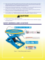
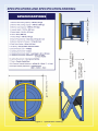
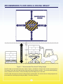
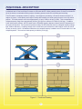
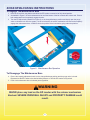
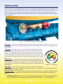
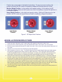
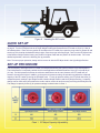
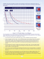
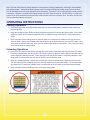
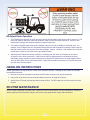
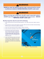
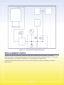
EZ LOADER
®
A U T O M AT I C PA L L E T P O S I T I O N E R
United States Patent
European Patent
5299906
0512775
Other Patents Pending
USA
United Kingdom
France
Germany
BISHAMON INDUSTRIES CORPORATION
5651 East Francis Street
Ontario, California 91761, USA
(909) 390-0055 (800) 231-3187
Date Placed in Service:
Serial Number:
Dealer:
Version 1.04
DECLARATION OF CONFORMITY
Name of manufacturer:
Bishamon Industries Corporation
Address of manufacturer: 5651 E. Francis Street
Ontario, California 91761, USA
Name of Manufacturer’s
authorized representative:
(Print name)
The Technical Construction File is maintained at:
IMS
ZI-Rue Saint Gilles
28800 BONNEVAL
I hereby declare that the following machinery complies with all the Essential Health and Safety
Requirements of the Machinery Directive 2006/42/EC as amended.
Machinery description:
EZ Loader (Pneumatic Load Positioner)
Serial no.:
1105***to date
Transposed Harmonized European Standards used:
EN 12100: 2010
EN 349: 1993+A1: 2008
EN 13857: 2008
EN 983:1996+A1:2008
EN 14121-1:2007
Safety of Machinery – General principles for design – Risk assessment
and risk reduction
Safety of Machinery - Minimum gaps to avoid crushing of parts of the
human body
Safety of Machinery - Safety distances to prevent danger zones being
reached by the upper and lower limbs
Safety of Machinery - Safety requirements for fluid power systems and
components – Pneumatics
Safety of Machinery – Risk assessment – Part 1: Principles
Additional standards used:
ANSI MH29.1-2008
Safety Requirements for Industrial Scissors Lifts
Name of responsible person:
Position of responsible person:
Robert M. Stone
Vice President of Operations
DECLARATION:
I declare that as the authorized responsible person, the above information in relation to the supply /
manufacture of this product is in conformity with the stated standards and other related documents
following the provisions of the EC Machinery Directive.
Signature of responsible person:
Robert M. Stone
Signature of authorized representative:
date: 09 / 08 /2011
day/mth/year
date:
(Print name)
/
/
day/mth/year
Table of Contents
Contents
Page
Getting Started ...........................................................................................................................................................1
Inspection ...................................................................................................................................................................1
General Warnings .......................................................................................................................................................1
Safety Warning Label Locations .................................................................................................................................2
Specifications and Specification Drawing ...................................................................................................................3
Recommended Floor Area & Ceiling Height ...............................................................................................................4
Functional Description ................................................................................................................................................5
Scissor Blocking Instructions ..................................................................................................................................... .6
Installation ................................................................................................................................................................. .7
Installation Instructions .............................................................................................................................................. .8
Quick Set-up .............................................................................................................................................................. .9
Set-up Procedure ...................................................................................................................................................... .9
Operating Instructions ...............................................................................................................................................11
Handling Instructions .................................................................................................................................................12
Routine Maintenance.................................................................................................................................................12
List of Figures
Figure 1
Figure 2
Figure 3
Figure 4
Figure 5
Figure 6
Figure 7
Figure 8
Figure 9
Figure 10
Figure 11
Figure 12
- Safety Warning Label Locations .............................................................................................................. 2
- Specification Drawing ............................................................................................................................. 3
- Recommended Floor Area & Ceiling Height ............................................................................................ 4
- Functional Drawing .................................................................................................................................. 5
- Maintenance Bar Operation ..................................................................................................................... 6
- EZ Loader Pneumatic Components......................................................................................................... 7
- Air Gauge ................................................................................................................................................. 7
- EZ Adjust Knob Positions ........................................................................................................................ 8
- Handling the EZ Loader ........................................................................................................................... 9
- EZ Loader Height vs Load Diagram ...................................................................................................... 10
- Fitting Disassembly................................................................................................................................ 13
- EZ Loader Pneumatic Schematic .......................................................................................................... 14
List Of Charts
Chart 1 - EZ Adjust Capacity Adjustability .............................................................................................................. 9
Chart 2 - EZ Loader Performance ........................................................................................................................ 15
GETTING STARTED
PLEASE READ THIS MANUAL CAREFULLY BEFORE USING THE EZ LOADER. The safety of all persons installing,
using or servicing the EZ Loader is of utmost importance to Bishamon. The EZ Loader is capable of supporting heavy
loads and is capable of causing SEVERE PERSONAL INJURY if used improperly or if certain safety precautions are
not taken. When properly used and maintained, the EZ Loader will provide many years of safe, trouble free service.
If you have any questions about any of the instructions in this manual or about the use of this product, PLEASE
contact your DEALER or Bishamon Industries Corporation.
INSPECTION
IMMEDIATELY upon receipt of the EZ Loader, remove all packing and strapping material and visually inspect the
unit for damage. Any damage to the unit MUST BE NOTED on the delivery receipt. After the preliminary inspection
is conducted, the unit should be thoroughly inspected for any concealed damage that was not readily apparent
during the preliminary inspection. Any concealed damage found that was not noted on the delivery receipt should be
IMMEDIATELY reported in writing TO THE DELIVERING CARRIER.
SAFETY DEFINITIONS
Bishamon uses the following system to identify the degree of risk associated with hazards and unsafe practices.
WARNING - Hazard or unsafe practice which, if not avoided, could result in DEATH or SEVERE
PERSONAL INJURY and PROPERTY DAMAGE.
CAUTION - Hazard or unsafe practice which, if not avoided, may result in MINOR or MODERATE
PERSONAL INJURY and PROPERTY DAMAGE.
GENERAL WARNINGS
WARNING
1.
READ THIS MANUAL COMPLETELY BEFORE USING AND THOROUGHLY UNDERSTAND AND FOLLOW
ALL SAFETY INSTRUCTIONS.
2.
The EZ Loader is designed for use with stable, uniformly distributed loads on a solid level floor. DO NOT
concentrate the load at one point on the pallet or platform. ALWAYS uniformly distribute each layer of load over
the supporting surface. DO NOT use the EZ Loader for any purpose other than its intended use.
3.
SHEARING HAZARD. ALWAYS keep hands and feet clear of the scissor mechanism and all moving
components. DO NOT put hands under the platform when in use. SEVERE PERSONAL INJURY could result.
4.
CRUSHING HAZARD. ALWAYS keep hands and feet clear of all moving components. DO NOT put feet on the
base frame when in use. SEVERE PERSONAL INJURY could result.
5.
PINCH POINT HAZARD. ALWAYS keep hands and fingers clear of the underside of the rotator ring. SEVERE
PERSONAL INJURY could result.
6.
NEVER sit, stand or ride on the platform or rotating surface. Moving components could cause loss of balance.
SEVERE PERSONAL INJURY could result.
7.
NEVER go under the platform until the load is removed and the scissor mechanism is blocked. SEVERE
PERSONAL INJURY could result.
8.
NEVER place any load on the EZ Loader with the scissor mechanism blocked. SEVERE PERSONAL INJURY
and PROPERTY DAMAGE could result.
9.
DO NOT overpressurize or overload the EZ Loader. ALWAYS stay within the designated pressure and capacity
ratings. SEVERE PERSONAL INJURY and PROPERTY DAMAGE could result.
1
10.
When removing a loaded pallet, ALWAYS raise the load until the bottom of the pallet clears the top of the EZ
Loader before backing up. ALWAYS stay well clear of the load while it is being removed from the EZ Loader.
SEVERE PERSONAL INJURY and PROPERTY DAMAGE could result.
11.
ALWAYS ensure all safety warning labels are in place and legible. If not, remove the EZ Loader from service
and replace the required labels. Refer to Figure 1 for label descriptions and locations.
12.
Before servicing any component in the EZ Loader’s pneumatic system, ALWAYS open the purge valve and
discharge all air pressure. SEVERE PERSONAL INJURY could result.
13.
DO NOT inflate the air spring when removed from the EZ Loader. Pressurizing the unrestricted air spring may
cause assembly to burst. SEVERE PERSONAL INJURY and PROPERTY DAMAGE could result.
CAUTION
1.
ALWAYS use clean dry air to pressurize the system.
2.
If the EZ Loader is equipped with the optional semi-live portability, ALWAYS remove the load before engaging
the portability wheels.
SAFETY WARNING LABEL LOCATIONS
Figure 1
Safety Warning Label Locations
2
SPECIFICATIONS AND SPECIFICATION DRAWING
Figure 2
Specification Drawing
3
RECOMMENDED FLOOR AREA & CEILING HEIGHT
Figure 3
Recommended Floor Area & Ceiling Height
The EZ Loader’s recommended floor area, shown in Figure 3, identifies the “Danger Zone” and the “Operating Zone”.
The Danger Zone is the area inside the base frame and under the platform structure. The recommended Operating
Zone is a distance of 39 inches (1 meter) extending beyond the danger zone on all sides.
The EZ Loader also requires a minimum ceiling height to operate within. The minimum floor-to-ceiling height should
be calculated as Load Height (including the pallet) + 42 inches (1068 mm).
4
FUNCTIONAL DESCRIPTION
The EZ Loader is a pneumatic pallet positioner designed to assist the operator when manually loading or unloading
a palletized load. As the load weight increases or decreases the EZ Loader gradually lowers or raises to maintain the
top of the load at a comfortable working height, eliminating operator strain due to bending and stretching.
The EZ Loader is completely variable in capacity. Load support is provided by a Firestone Airstroke Actuator in a
captive air system. Load capacity and height is initially determined by the initial system pressure in the fully raised
position. The initial pressure varies from approximately 10 psi (0.7 Bar) to 60 psi (4.1 Bar). This corresponds to a
collapsed capacity range from approximately 250 lbs (113 kgs) to a maximum of 2700 lbs (1225 kgs). In addition
to the initial system pressure, the EZ Loader has the EZ Adjust capacity adjustment feature which is independent of
the system air pressure. For any initial air pressure setting, the EZ Loader has three (3) collapsed capacity settings;
light, medium and heavy. A capacity change can be made at any time without the need to add or remove air and is
as easy as turning a knob. All additional load above the collapsed capacity is added to the EZ Loader while it is in the
collapsed position. The maximum load capacity is 4000 lbs (1814 kgs).
Figure 4
Functional Drawing
5
SCISSOR BLOCKING INSTRUCTIONS
To Engage The Maintenance Bars
1.
2.
3.
Remove all load from the platform and allow the EZ Loader to extend to its fully raised position.
As detailed in Figure 5, lift each maintenance bar until the bottom of the bar contacts the scissor axle. Ensure
both maintenance bars completely engage the axle.
Turn the EZ Adjust knob (identified in Figure 6), to the charge/discharge position and slowly open the purge
valve to release the air from the system. As the air releases, the scissor mechanism will lower and completely
engage the maintenance bars. ALWAYS check the position of the bars before going under the platform.
Figure 5
Maintenance Bar Operation
To Disengage The Maintenance Bars
4.
5.
Ensure the capacity adjustment knob is in the charge/discharge position and the purge valve is closed.
Repressurize the EZ Loader to the desired initial pressure or until the EZ Loader is fully raised.
Push each maintenance bar to its lowest (stored) position.
WARNING
NEVER place any load on the EZ Loader with the scissor mechanism
blocked. SEVERE PERSONAL INJURY and PROPERTY DAMAGE could
result.
6
INSTALLATION
Installation of the EZ Loader is a simple process; however, certain precautions must be taken to ensure years of
trouble free service. The EZ Loader requires clean, dry, compressed air to operate properly. A filter and regulator with
a pressure gauge should be installed on an air line in the installation area before initially charging the system for use.
Before you begin, locate and identify the pneumatic components detailed in Figure 6. These components will be
referred to in the Installation and the Set-Up procedures. Make sure you understand the function of each component
before proceeding.
Figure 6
EZ Loader Pneumatic Components
Air Chuck - The air chuck is supplied the EZ Loader and is used to charge the EZ Loader with air. The air chuck
body is supplied with 1/4 inch female pipe threads and must be attached to the end of the air line extending from the
filter/regulator.
Air Gauge - The air gauge, Figure 7, indicates the EZ Loader’s internal system
pressure. Green identifies the initial pressure range for the EZ Loader in the raised
position. The initial system pressure should be between 10 psi (0.7 bar) and 60 psi
(4.1 bar). Yellow identifies the operation pressure range when the EZ Loader is fully
loaded and collapsed. The maximum operational pressure is 135 psi (9.3 bar). Under
no circumstance should be EZ Loader be operated in the red range above 135 psi (9.3
bar).
Purge Valve - The purge valve is a manual one way valve used to release air from
the EZ Loader. Turning the valve counter-clockwise opens the valve and releases air
from the system. Turn the valve clockwise to close. The valve should be closed with
finger tight pressure. DO NOT use a wrench to close the valve. Leakage may occur if
over-tightened.
Figure 7
Air Gauge
Tank Valve - The tank valve is a one way valve used to charge the EZ Loader with
air. The end of the tank valve is designed to mate with the air chuck. Pressing the air chuck against the end of the
tank valve allows air to enter the system.
EZ Adjust Knob - The EZ Adjust capacity adjustment knob allows the operator to change the collapsed capacity
of the EZ Loader without adding or removing air from the system. The knob’s three (3) positions are identified in
Figure 8.
Light Weight Position - is also the air charge/discharge position. Always turn the EZ Adjust
knob to this position before adding or removing air from the system. The Light Weight
7
Position also corresponds to the lightest load setting. For any air pressure setting, this
position will allow the EZ Loader to completely collapse with the least amount of load.
Medium Weight Position - is the medium load capacity setting. At this setting, the EZ
Loader will collapse slower and will require more load to completely compress the platform to
its collapsed position.
Heavy Weight Position - is the high load capacity setting. With the EZ Adjust knob in this
position, the EZ Loader will require the most load to completely collapse the platform.
Figure 8
EZ Adjust Knob Positions
INSTALLATION INSTRUCTIONS
1.
2.
3.
4.
5.
6.
7.
8.
Make sure the installation area is clean before starting. Check the installation surface to ensure it is relatively
smooth and level. Otherwise, the EZ Loader base frame should be shimmed to make it level.
Using a fork lift or similar equipment, move the palletized EZ Loader to the location it is to be installed.
Remove the steel bands securing the EZ Loader to the pallet. Next, remove all packing material and place it off
to the side.
Attach the air chuck to the air line extending from the filter/regulator.
Set the regulator to 60 psi (4.1 bar). Turn the EZ Adjust knob to the Light Weight Position and initially charge
the system by engaging the air chuck to the EZ Loader’s tank valve. The air spring will inflate and the EZ
Loader will gradually extend to its maximum raised height. If escaping air is detected, close the purge valve
(finger tight). Allow the system to completely pressurize and disengage the air line from the EZ Loader.
Using a fork lift, position the forks under the platform structure, as detailed in Figure 9. Lift the EZ Loader off
the pallet. Next, remove the pallet and place if off to the side. Position the EZ Loader in the desired location.
Securing the EZ Loader to the floor may be preferred in some applications. If so, the base frame of the EZ
Loader has 4 pre drilled holes for lagging the unit securely to the floor. Using the 4 holes as a template, mark
the holes on the floor. Using the fork lift, shift the position of the EZ Loader to allow room for drilling, then drill.
When complete, reposition the lift and install anchors lagging the EZ Loader securely to the floor. NOTE: Make
sure the base angles are fully supported along their entire length with shims or concrete grout.
The EZ Loader is now ready for operation. Refer to the Set Up procedure to properly set the initial pressure for
the desired capacity.
8
Figure 9
Handling the EZ Loader
QUICK SET-UP
The EZ Loader is complete variable in capacity and very easy to set up. Complete the installation instructions detailed
on page 8 Turn the EZ Adjust knob to the Light Weight Position and pressurize the EZ Loader to 60 psi (4.1 bar) in
the raised position. Place all or any portion of the load on the EZ Loader, then open the purge valve to release air and
set the top of the load at the desired working height. Close the purge valve finger tight. Next, turn the EZ Adjust knob
to the Medium Weight Position leaving one position for lighter loads and one position for heavier loads. For a more
detailed explanation, refer to the following set up procedure.
Note: To ensure proper operation, always add or remove air with the EZ Adjust knob in the Light Weight Position.
SET-UP PROCEDURE
The load capacity and height of the EZ Loader is initially determined by the system pressure in the raised position.
The initial pressure is completely variable and for most applications should be between 10 psi (0.7 bar) and 60 psi
(4.1 bar). An initial pressure less than the minimum stated above can be used; however, the EZ Loader will not
extend to its maximum height. In addition, to the system air pressure setting, the operator may adjust the collapsed
capacity of the EZ Loader by turning the EZ Adjust knob. For any air pressure setting, the EZ Loader has three (3)
collapsed capacity settings; Light Weight Position, Medium Weight Position and Heavy Weight Position. A capacity
change can be made at any time without the need to add or remove air and is as easy as turning the EZ Adjust knob.
The change in capacity for two (2) air pressure settings is shown below in Chart 1.
Chart 1
EZ Adjust Capacity Adjustability
9
A diagram of the rotator ring height as it relates to the load weight for the EZ Loader is shown below in Figure 10.
Figure 10 illustrates the change in performance due to both changes in initial pressure and changes in the EZ Adjust
knob position.
Figure 10
EZ Loader Height vs. Load Diagram
For most applications, the EZ Loader should be completely collapsed at approximately 75 percent of the total load
(load + pallet weight). The remaining load (usually the last layer) is added to the EZ Loader while it is in the collapsed
position. To set up the EZ Loader for use, complete steps 1 6 below.
1.
The EZ Loader must be properly installed before using. Refer to installation instructions on page 8.
2.
Set the air regulator to 60 psi (4.1 bar). Turn the EZ Adjust knob to the Light Weight Position and completely
pressurize the EZ Loader. Check the pressure gauge on the EZ Loader to ensure the system pressure is
the same as the regulator setting. Disengage the air chuck from the tank valve and store the air line in a
convenient location. Ensure the purge valve is closed finger tight and disengage the maintenance bars, if
required.
3.
Place the pallet and 75 percent of a lighter than average load on the EZ Loader. Check the platform height.
If the EZ Loader is not completely collapsed, open the purge valve slowly and release air until the minimum
height is obtained. Close the purge valve.
4.
Using a fork lift, remove the loaded pallet and allow the EZ Loader to return to its raised position. If a dedicated
air line is being used, set the air regulator to the initial pressure on the gauge. Otherwise, record the setting for
future use.
5.
With the EZ Loader in the fully raised position, turn the EZ Adjust knob to the Medium Weight Position. This
provides for one lighter than average weight setting; as well as, one heavier than average weight setting.
6.
The EZ Loader is now ready for use. Should the load capacity vary, adjustments in the load height or collapsed
capacity can easily be made by turning the EZ Adjust knob.
10
Note: The ideal initial pressure setting depends on many factors; including load density, load height, load variability
and operator height. Should the desired response require a slightly stiffer spring setting, simply remove the load,
turn the EZ Adjust knob to the Light Weight Position and add air. Typically, a 5 psi (0.3 bar) change in initial pressure
is adequate. Likewise, if a slightly softer spring setting is desired, simple remove air. The EZ Loader is a captive air
system much like an automotive tire and will lose small amounts of air over a period of time. Therefore, air will have
to be occasionally added to the system.
OPERATING INSTRUCTIONS
Loading Operations
1.
Place the empty pallet on the EZ Loader rotator ring. Be sure that the pallet is centered on the rotator ring
before beginning.
2.
Begin the loading process. Always uniformly distribute each layer of load over the pallet surface. As the load
weight increases, the EZ Loader will gradually lower to maintain the top of the load at a convenient working
height.
3.
Upon completion of the loading process, rotate the pallet to a position that is suitable for the fork lift forks to
enter the pallet. Slowly lift the loaded pallet until the bottom of the pallet clears the top of the EZ Loader. Next,
slowly back up until the load is well clear of the EZ Loader’s operating zone and others. Then, lower the load to
a convenient height for transportation.
Unloading Operations
4.
Using a fork lift, lift the loaded pallet to a height where the bottom of the pallet clears the top of the EZ Loader.
Position the loaded pallet over the top of the EZ Loader rotator ring. Be sure that the pallet is centered over the
rotator ring before lowering the load. Slowly lower the load until the EZ Loader is completely collapsed. Next,
slowly back up until the forks are well clear of the EZ Loader’s operating zone.
5.
Begin the unloading process. Always remove each layer of load completely before beginning the next layer.
This will ensure that the remaining layers are uniformly distributed over the pallet surface. As the load weight
decreases, the EZ Loader will gradually raise to maintain the top of the load at a convenient working height.
6.
Upon completion of the unloading process, remove the empty pallet.
11
EZ Adjust Knob Operation
1.
The EZ Adjust knob provides for quick and easy capacity changes without the need to add or remove air. The
amount of capacity change for each knob position is relative to the initial system pressure. However, each
knob position changes the collapsed capacity by approximately 40%.
2.
The position of the EZ Adjust knob can be changed at any time during the loading or unloading cycle. For
example, if the EZ Adjust knob is in the Medium Weight Position and the platform is settling to quickly with the
first layer of load, simply turn the knob to the Heavy Weight Position. Likewise, if the response is too stiff after
the first layer of load, turn the knob to the Light Weight Position.
3.
Adjusting the EZ Adjust knob during a loading or unloading cycle will cause an imbalance in the system
air pressure in the various reservoirs. If after several mid-cycle adjustments the performance becomes
undesirable, simply equalize the system pressure by turning the EZ Adjust knob to the Light Weight Position
when the EZ Loader is in the fully raised position. Wait a few seconds for the pressure to equalize and return
the knob to the desired position.
HANDLING INSTRUCTIONS
Certain applications may require the EZ Loader to be relocated frequently. Handling the EZ Loader can be easily
accomplished as follows:
1.
Remove all load from the platform and allow the EZ Loader to extend to its fully raised position.
2.
Using a fork lift, position the forks under the platform structure, as detailed in Figure 9.
3.
Slowly lift the EZ Loader until the base frame clears the floor. The EZ Loader can now be moved to the next
location.
ROUTINE MAINTENANCE
The EZ Loader is designed to provide years of trouble free service and requires very little maintenance. However, a
routine inspection and maintenance program will prevent costly replacement of parts and/or downtime.
12
WARNING
NEVER go under the platform until the load is removed and the scissor
mechanism is blocked. SEVERE PERSONAL INJURY could result.
WARNING
Before servicing any component in the EZ Loader’s pneumatic system,
ALWAYS open the purge valve and discharge all air pressure. SEVERE
PERSONAL INJURY could result.
Monthly inspection should consist of the following:
1.
Inspect the snap rings at all rollers and linkage assemblies. If not in place and/or secure, replace or repair at
once.
2.
Inspect all rollers for signs of wear. Replace as necessary. Rollers and axles have lifetime lubricated bearings;
therefore, they do not need to be greased or lubricated.
3.
Inspect the air spring retaining screws for tightness. Tighten if necessary.
4.
Inspect the rotator ring bearings for ease of operation. Replace if necessary.
5.
Should removal of the air lines be required,
mark the initial position before removing the
fitting nut. When reinstalling, first tighten the
nut by hand, then using a wrench rotate the
nut to the original position. Tighten the nut an
additional 1/8 turn. Do not over tighten as air
leakage may occur.
6.
Inspect the EZ Adjust knob and valve body for
proper operation. If disassembly of the valve
is required, always engage the maintenance
bars and open the purge valve to completely
discharge all air pressure before disassembling
the valve.
Figure 11
13
Fitting Disassembly
Figure 12
EZ Loader Pneumatic Schematic
REPLACEMENT PARTS
Bishamon has carefully selected the components used in the manufacture of the EZ Loader. In the event
replacement parts are required, ALWAYS use genuine EZ Loader components provided by Bishamon. These parts
can be obtained from your Bishamon DEALER or by contacting Bishamon Industries Corp.
For detailed exploded views and parts lists contact your dealer, Bishamon Industries Corporation or visit www.
bishamon.com.
14
Chart 2
EZ Loader Performance
Notes:
1.
The above chart is for reference only to illustrate the capacity variability of the EZ Loader. Other initial
pressures may be better suited for a specific loading/unloading application.
2.
There are multiple EZ Loader settings for most pallet weights. For example, consider a total pallet load of 1650
lbs. Three (3) of the possible settings are:
25 psi with the EZ Adjust knob in position three,
35 psi with the EZ Adjust knob in position two,
50 psi with the EZ Adjust knob in position one.
Each setting will provide a slightly different load response and the ideal setting will depend of the load height,
number of layers in the load and the operator height.
3.
The above chart assumes a typical load height with the last layer of load being placed on the pallet with the EZ
Loader fully compressed.
4.
The EZ Loader is completely variable in capacity and any initial pressure setting between 10 psi and 60 psi
may be used.
15