1
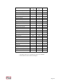
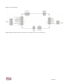
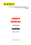
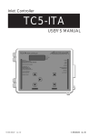
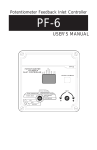
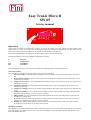
Easy Tronic Micro II
SW 05
Service manual
Operation
Unless there are alarms or maintenance warnings, at start-up the display will show software release installed. This
manual refers to release U05. After start up the display shows the pressure, the temperature, the total hours and the
motor hours. Briefly press FUNCTION (F) to go from one information to the next one.
Pressures and temperatures are displayed only if the relative sensors are enabled (default).
Pressing the button F will show the different information as follows
P
t
HT
HL
Pressure,
Temperature,
Total Hours
Load hours
If the FUNCTION (F) key is not used for 10 seconds, the display goes back showing the pressure.
Start-up procedure:
Press START (I). If no alarm is present, the start-up cycle will be initiated:
a) Start-up standby: the standby LED will flash for a 20-second delay from the last time the motor was turned
off.
b) Phase sequence check: the system verifies the presence of the phases in the first 30 seconds and their correct
sequence for 10 seconds.
c) Compressor start-up: the screw LED flashes and energizes the line relay and the star relay; this stage lasts for
a fixed period of 5 sec.
d) Star-delta transition: the relay remains energized while the star relay is de-energized; this stage lasts for a
fixed period of 5 msec.
e) Compressor running: the line relay remains energized and the delta relay is also energized; this stage lasts for
2 sec.
f) Compressor loading: the screw LED remains steadily on and the load solenoid valve relay is energized; this
stage lasts until the “Idling pressure set point” is reached.
g) Idling running: the screw LED flashes and the load solenoid valve relay is de-energized; this stage lasts for
the time set as “Idling time”.
If in the meantime the pressure drops below the value entered as “Load pressure set point”, the cycle restarts
from point a), otherwise the compressor goes on standby.
h) Standby: the standby LED remains on and the motor is off; when the pressure reaches the value entered as
“Load pressure set point” the cycle restarts from point a).
Shutdown procedure:
Press RESET (0) to start the shutdown procedure. The load solenoid valve is de-energized and the idling cycle is started
for a time equal to the “Shutdown delay time” (the screw LED flashes), after which the controller switches off (screw
LED and standby LED off).
Remote control
Remote pressure
When remote control is enabled, load and idling operations are governed by the remote input. In this configuration the
controller will make sure that the remote input operates within the range of preset values (load and idling set points) set
in the controller itself. Pressure settings input in the controller (local) have to be wider than the pressure settings set in
the remote device (example, remote settings, idling 9 bar, load 8 bar. Controller local settings: Idling 9,5 bar, load 7,5
bar).
If the idling pressure locally set in the controller is reached due to a malfunction in the remote control, the controller will
assume control of compressor operations and make it run according to the local settings, and the display will show the
message R_ALL (remote alarm).
If the malfunction is resolved, i.e., the remote control intervenes before the local controller idling settings, compressor
functions are resumed by the remote control and the message R_ALL disappears.
When remote pressure control is required the LOCAL pressure settings must be wider than the REMOTE pressure
settings (example. REMOTE settings: Idling pressure 9.0 bar, load 8.0 bar. LOCAL settings: idling 9.5 bar, load 7.5
bar).
During normal operation (with pressure sensor enabled) the display shows the pressure with the prefix Pr (used to
indicate that the pressure is controlled remotely). The status of the input (with Pr_OFF or Pr_ON) is displayed after any
switch for 5 seconds only.
With pressure sensor disabled
Remote ON/OFF
Enabling the remote ON/OFF feature (remote parameter set to 2) the compressor can be started through the remote
input. The remote start is working only with hte LOCAL START enabled (button I pressed).
The display shows different indications, depending on the status of the LOCAL/REMOTE settings. Please refer to the
following table:
Pressure sensor
Enabled
Start LOCAL
OFF
OFF
ON
Input REMOTE
OFF
ON
OFF
ON
ON
Non abilitato
DISPLAY
r_OFF
r_ON
r_OFF flashing (compresor ready to start as soon as
the remote input is set to ON)
r_ON for 5sec
Then the display shows the pressure with prefix P
Same as above. But the pressure value is not displayed.
The display will show (P_ON, P_OFF); depending on
the status of the pressure switch
Tab.1
Menus and parameters
The controller settings are based several parameters which can be accessed and edited through 3 menus.
-User Menu (see Tab. 2)
-Service Menu (see Tab. 3)
The Service Menu Menu can be accessed only by pressing a combination of keys and entering a password.
Once you have accessed a menu, press START (increase) and RESET (decrease) to go the parameter you want to edit;
every parameter is identified by a letter and a number. After selecting a parameter, press FUNCTION to view its current
value, then press START or RESET to edit the value. Once you have changed the parameter, press FUNCTION to
confirm the changes and return to the parameter index.
If no key is pressed in the parameter index for 5 seconds, the menu is automatically exited.
The Service Menu can be accessed only by password.
Enter the password one digit at a time. After you press the key combination the display will show 4 zeroes, and the first
one on the left will be flashing. Press START to edit the flashing digit; press RESET to select the digit to be edited;
press FUNCTION to confirm the password: if the password is correct you can access the menu, otherwise you will be
taken back to the main screen.
Pag 2/10
Parameters
−Oil temperature pre-alarm (delta): the delta of temperature (in °C) can be set as a function of the maximum alarm
temperature. For example, if the maximum temperature is set at 120 °C and the delta is 10 °C, the temperature prealarm will be given at 110 °C by the flashing of the oil temperature alarm (this parameter is significant only if the
temperature sensor is enabled).
−Maximum oil temperature: determines the maximum oil temperature (in °C) above which the system will report an
alarm and stop the compressor (this parameter is significant only if the temperature sensor is enabled).
−Minimum oil temperature: determines the minimum oil temperature (in °C) below which the system will report an
alarm and stop the compressor (this parameter is significant only if the temperature sensor is enabled).
−Fan starting temperature: determines the fan starting temperature; the threshold value has a fixed hysteresis of 10°C.
For example, if the fan starting temperature is set at 100°C, the fan will start at 100°C and stop at 90°C oil temperature
(this parameter is significant only if the temperature sensor is enabled).
−Thermal gradient: determines the maximum variation per second of the oil temperature, above which the system will
report an alarm and stop the compressor (this parameter is significant only if the temperature sensor is enabled).
.
−Maximum alarm pressure: determines the maximum pressure above which the system will report an alarm and stop
the compressor (this parameter is significant only if the pressure sensor is enabled).
−Maximum settable pressure: determines the maximum pressure settable as the idling pressure set point (this
parameter is significant only if the pressure sensor is enabled).
−Idling time: determines the delay (in seconds) between the time the load solenoid valve is de-energized upon reaching
the desired pressure and the time the motor stops.
−Shutdown delay time: determines the compressor shutdown delay when pressing RESET; when the compressor is on,
the solenoid valve is de-energized (if found energized) and the motor keeps running until the delay is over.
−Pressure sensor enable: enables either the analog pressure sensor or the electromechanical pressure switch (one
excludes the other).
−Temperature sensor enable: enables either the analog temperature sensor or the electromechanical thermostat (one
excludes the other).
−Automatic start enable: enables automatic restarting: if enabled the compressor restarts automatically after a power
failure; initial start-up is still achieved by pressing the START (I) key on the panel.
−Internal phase sequence enable: enables either the board’s internal phase sequence or the phase sequence of an
external device.
−Remote enable: enables REMOTE Pressure or remote ON/OFF, (default, no remote control)
−Idling pressure set point: indicates the residual pressure required for the compressor to start: the maximum settable
value is determined by the parameter “Maximum settable pressure”.
−Load pressure set point: indicates the operating pressure at which the compressor stops; the maximum settable value
is fixed at 0.5 bar lower than the “Idling pressure set point”.
−Unit of measurement: lets you select the unit of measurement for the pressure (bar or psi).
−Oil hours left: indicates the number of hours left before oil maintenance is due; when the count reaches zero the
display will show a maintenance code (see “Maintenance Warnings”). The counter is updated every hour of
compressor operating time.
Pag 3/10
−Oil filter hours left: indicates the number of hours left before oil filter maintenance is due; when the count reaches
zero the display will show a maintenance code (see “Maintenance Warnings”). The counter is updated every hour of
compressor operating time.
−Air filter hours left: indicates the number of hours left before air filter maintenance is due; when the count reaches
zero the display will show a maintenance code (see “Maintenance Warnings”). The counter is updated every hour of
compressor operating time.
−Oil separator hours left: indicates the number of hours left before oil separator maintenance is due; when the count
reaches zero the display will show a maintenance code (see “Maintenance Warnings”). The counter is updated every
hour of compressor operating time.
−Total hours: shows the total number of hours during which the compressor was powered; can be changed.
−Load hours: shows the total number of hours during which the compressor was on load; can be changed.
−Reset parameters: this function is for quickly configuring the board to the type of unit on which it is to be installed.
There are 2 settings, one for CUBE units and one for MC units. The default value is 0; set it to 1 to configure the board
for CUBE units (see Tab. 1) or to 2 for MC units (see Tab. 1). The settings will be updated when leaving the menu
(Factory or Service). By default, the controller is configured to work with CUBE units.
Pag 4/10
PARAMETER
DEFAULT
CUBE
DEFAULT
MC
[...]
Oil temperature pre-alarm (delta)
5
5*
°C
Maximum oil temperature
110
110*
°C
Minimum oil temperature
-7
-7*
°C
Fan starting temperature
80
80*
°C
Thermal gradient
5
5*
°C/sec
Maximum alarm pressure
13.7
13.7*
bar
Maximum settable pressure
11.0
11.0*
bar
Idling time
75
75
sec
Shutdown delay time
35
35
sec
Pressure sensor enable
1
0
No/Yes
Temperature sensor enable
1
0
No/Yes
Automatic start enable
0
0
No/Yes
Internal phase sequence enable
1
0
No/Yes
Remote control
0
0
0, 1, 2
Oil hours left
4000
3000
Hours
Oil filter hours left
4000
3000
Hours
Air filter hours left
2000
1500
Hours
Oil separator hours left
4000
3000
Hours
Total hours
------**
------**
Hours
Load hours
------**
------**
Hours
Idling pressure set point
10.0
10.0*
bar
Load pressure set point
8.5
8.5*
bar
1
1*
[psi/bar]
Unit of measurement
Tab. 1 Default parameters for type of compressor
* Parameters that are not used when the sensors are disabled
**The number of hours remains unchanged
Pag 5/10
User Menu
The User Menu (see Tab. 2) can be accessed only when the compressor is off; to access the menu, press the
FUNCTION key for at least 5 seconds.
No.
PARAMETER
MIN
DEFAULT
MAX
[...]
bar
U0
Idling pressure set point
0.5
10.0
15.0
U1
Load pressure set point
0
8.5
*
U2
Unit of measurement
0
1**
1
bar
psi/bar
Tab. 2 User Menu for setting parameters
* the maximum value for the load pressure set point is the idling pressure set point – 0.5bar
** 1=bar, 0=psi
Service Menu
The Service Menu (see Tab. 3) can be accessed only when the compressor is off or during an alarm situation; to access
the menu, press FUNCTION + RESET for at least 5 seconds, after which you will be asked to enter the password.
No.
PARAMETER
MIN
DEFAULT
MAX
[...]
A0
Fan starting temperature
0
80
150
°C
A1
Idling time
30
75
900
sec
A2
Shutdown delay time
30
60
900
sec
A3
Pressure sensor enable
0
1*
1
No/Yes
A4
Temperature sensor enable
0
1*
1
No/Yes
A5
Automatic start enable
0
0*
1
No/Yes
A6
Internal phase sequence enable
0
1*
1
No/Yes
A7
Oil hours left
0
2000
65536
Hours
A8
Oil filter hours left
0
2000
65536
Hours
A9
Air filter hours left
0
2000
65536
Hours
A10
Oil separator hours left
0
4000
A11
Total hours
------**
------**
Hours
A12
Load hours
------**
------**
Hours
A13
Reset parameters**
0
0
2
A14
Remote control enable
0
0
2
65536
Hours
0 = No Remote
1 = Remote pressure
2 = Remote ON/OFF
Tab. 3 Service Menu for setting parameters
* 1=enabled, 0=not enabled
** Function for setting the default parameters according to the type of unit on which the board is
to be installed: Cube (Reset parameters =1) or MC (Reset parameters =2)
Pag 6/10
Maintenance warnings
The compressor is equipped with 4 counters that count down every hour of motor running. When a counter reaches zero,
the display shows a message informing that the compressor needs servicing. No parameter (pressure, temperature, total
hours, motor hours) can be viewed on the display until the warning message is reset from the Service Menu (see Tab. 5).
If multiple maintenance warnings occur at the same time, the warnings are shown on the display in sequence.
Warning
DESCRIPTION
CH1
Oil hours left
CH2
Oil filter hours left
CH3
Air filter hours left
CH4
Oil separator hours left
Tab. 5 Maintenance warnings
Alarms
Alarms are shown by code messages that appear on the display and by red LEDs that light up beneath them.
There are 11 alarms, 6 of which are shown on the display (see Tab. 6). If multiple alarms occur at the same time, the
messages are shown on the display in sequence.
All alarms make the compressor stop; the compressor can be restarted only after the cause of the alarm has been
removed. The alarm messages remain displayed visible even after their cause has been removed; to cancel the message
you need to press RESET.
The presence of water (option) is checked every time the controller is powered on and every time the motor is stopped
or on standby for more than 5 minutes. The first 10 times the presence of water is detected, the warning is given only by
the flashing of the respective red LED; the 11th time, the compressor will stop until the water is removed.
The Service Menu remain accessible.
ALARM
DESCRIPTION
Indicates presence of water in the oil separator. When flashing it means that water has been detected but
the unit is still in operation; with the compressor off, press RESET to turn off the flashing LED. If the
LED remains on steady, the unit cannot be started until the water is removed (1)
Indicates a faulty connection to the power mains (1)
Means that the motor’s maximum temperature has been exceeded (1)
Means that the maximum oil temperature has been exceeded (if the pressure sensor is enabled, the prealarm is indicated by a flashing LED but the compressor remains in operation)
Means that there was a power failure the last time the compressor was used. The unit remains in
operation. To cancel the warning, press RESET with the compressor off. (this alarm works only if
Automatic Start is not enabled).
AL1
Indicates a faulty or broken temperature sensor (if enabled)
AL2
Indicates a faulty or broken pressure sensor (if enabled)
AL3
Indicates a missing phase or means that the phase sequence transformer is not working (if the internal
phase sequence is enabled)
AL4
Means that the pressure has reached the maximum alarm threshold (if the pressure sensor is enabled)
AL5
Means that the temperature is rapidly rising above the preset thermal drift (if the temperature sensor is
enabled)
AL6
Means that the emergency button was pressed
1) If it’s present this alarm only, the display indicates an horizontal line.
Tab. 6 Alarm messages
Pag 7/10
Connection diagram
Fig. 1 Board layout
Electrical and mechanical details
Electrical details
Power supply:
Max. demand at 12 VAC:
Working Temperature
Relays:
Max. relay current:
Inputs voltage:
Supply voltage 4-20 mA:
Mechanical details
Panel dimensions:
Fastening holes:
12 VAC ±10%
200 mA
-15/+70°C
5 (with NO contact connected to the common line)
230 VAC 8 A res. (the contacts ARE NOT suitable for large loads and can only be
used for controlling the relays and external power contactors)
12 VAC ±10%
8 VDC (Note: The board is designed to work with pressure sensors that accept a
minimum supply voltage of 8 V)
150x70 mm
4x Ø5 mm
Pag 8/10
Pag 9/10
Fig. 2 Connection diagram
Fig. 3 Diagram showing the proper connection of a new board on the previous wiring layout.
Pag 10/10