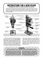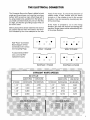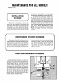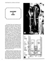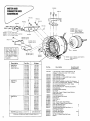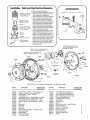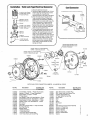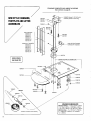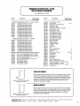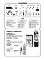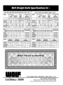
1
PARTS AND SERVICE MANUAL 5570 CREEK ROAD, CINCINNATI, OHIO 45242/ U.S.A. 1sf/Since 1888 TOLL FREE 1-800-543-WOLF Phone: 513-791-5194/ FAX 513-791-0925 e-mail: [email protected] • Web Site: www.wolfmachine.com C"O"N"T"E"N"T"S SECTION I - SERVICE MANUAL Instructions for a NEW Pacer Maintenance for All Models Installation of Knife Maintenance of Knife and Standard Knife and Crosshead Alignment Lubrication Adjustment of Guide Changing the Rubber Drive ., Care of Rollers and Retainers Removal of the Follower Maintenance for Stone Sharpener When Sharpening a New Knife Emery Wheel Applications Changing the Grinding Wheels How to Disassemble the Sharpener Proper Adjustment of the Sharpener Adjustment of the Presser Foot Lock Assembly Maintenance of Belt Sharpener When Sharpening a New Knife Changing Emery Belts Emery Belt Applications Proper Adjustment of Sharpener Adjustment of Presser Foot Lock Assembly How to Disassemble Sharpener ., SECTION II - PARTS MANUAL Reference Page Drive Assembly & Numbers Motor, Connector Box Assemblies & Numbers Motor, Cord Connectors Assemblies & Numbers Motor, Connector Box Assemblies & Numbers for Pacer 100 Motor, Cord Connectors Assemblies & Numbers for Pacer 100 Standard, Insert, Footplate Assemblies & Numbers : Stone Sharpener & Numbers Belt Sharpener & Numbers Backplate Assembly & Numbers Series X Stone Sharpener & Numbers Knives Accessories Pacer Guard , Lamp, Clamp, etc Slider Oiler & Installation Instructions Twin Flow Wetter & Installation Instructions Tools, Lubricants & Cleaning Agents Straight Knife Specifications I Guarantee . 1 thru 14 . . . . . . .. . . . . . . . . . . 1,2 . . . . .. . . 3-6 4 4 4 5 6 7 7 7 8-11 8 8 9 9 10 11 12-14 12 12 12 13 14 14 15 thru 38 . 15 .. .. . . .. . . 26,27 . 28,29 .. . . 30,31 . . . . . . 16,17 18 19 20 21 22-25 32 33 34 34 35 36 37 38 WOLF STRAIGUT KNIFE CLOTU CUTI1NG MACIIINES Wolf Machine offers two basic machine models in the Straight Knife Cloth Cutting Machines: The Stone Sharpener Series and The Belt Sharpener Series. Both series are available in 5", 6", T, 8", 10" and 14" models. All have the same great quality engineering that Wolf has built its reputation on! Belt Sharpened Series vm &. XI The Wolf Belt Sharpened Series has a unique emery belt sharpening head which produces an excep tionally fine honed, slick blade edge that is superior for cutting finely textured materials and for special trim ming. Emery belts graded fine, medium, coarse and very coarse are used to change the blade edge for cut ting medium to coarse or hard fabrics. A simplified bevel adjustment control provides easy positive knife bevel selection. (See #1 above and page 13). Emery belt replacement is accomplished in seconds with a fin ger-tip quick-change mechanism (See #2 above & page 12). Stone Sharpened Series VI, VII &. X The Wolf Stone Sharpened Series is a stone sharp ened straight knife which is the most versatile and eco nomical machine for a wide variety of fabric cutting. Tension can be adjusted to balance emery wheel pres sure with extreme sensitivity (See #3 above and pages 8 and 9). The mechanism is self locking to maintain positive adjustment. Millimeter Equivalents, Machines Sizes: 5"= 127mm; 6"= 152mm; T' = 178mm; 8" = 203mm; 10"= 254mm; 14"= 356mm. INSTRUCTIONS FOR ANEW PACER CAUTION: 2 3 READ PAGES & BEFORE OPERATING THIS MACHINE. This Parts and Service Manual has been supplied to enable you to take the best possible care of your new machine. By carefully following the service instructions contained in this manual, you will be assured of the best performance with minimum maintenance of your Wolf Pacer. Corrections of major maintenance problems should be made at the factory or in the field by a qualified, factory-trained main tenance representative. SHARPENER, STARTING " LEVER SHARPENER HOUSING THUMB SCREWS (TO REMOVE SHARPENER) LUBRICATOR PRESSERFOOT LIFT HOOK TENSION BUDON BALANCE SCREW ELECTRICAL CONNECTION BOX KNOB BLADE ADJUST PRESSERFOOT OPERATING LEVER (Stone Sharpener) CD CARRYING HANDLE KNIFE OPERATING HANDLE SHARPENER HEAD (Stone Sharpener) PRESSER FOOT ON-OFF SWITCH When your new Pacer is first put into service, allow the machine to come to room tempera ture. Before the machine is plugged in make sure that the Motor rotates freely and the Knife is prop erly set, (turn the Rotor Knob at the rear of the machine - see above). The Knife should not strike the table when Knob is rotated. Caution: The Knife is factory sharpened and ready to use on a new machine. Also check to see if the Crosshead slides freely between the Guide Plates by unscrewing the two thumb screws (see above) on the front of the machine and removing the sharp ener and turning the Rotor Knob. If the Crosshead does not slide freely see page 6 for, Adjustment of the Guides. Note: Do not oil graphite Crosshead Guides. (Heavy duty steel require lubrication. THE ELECTRICAL CONNECTOR The Connector Box on the Pacer is drilled for both single and three phrase cord coupling (as shown below). Wolf (as well as many other) plugs will fit by using smaller pins available from the factory. If you install connection block pins, be sure that they are tight, and that the grounding support knob on the cord is used. head of the motor. To check the direction of rotation make a flash contact with the switch turned on. If the rotation is not in the correct direction, it can be reversed by reversing any two of the circuit lines. If the motor is allowed to run in the wrong direction, the crank will unscrew and damage the machine. Single phase motors automatically turn in the proper direction. Before placing three phase machines into service be positive that the motor will rotate in the direc tion indicated by the arrow stamped on the rear Wolf "Pacer" Connection Block Diagram of Post Combinations for various Cord Coupling Plugs. To assure best perform ance, use only Wolf replacement parts. () e '" \,/ ,/ "" '" \,/ • "" '" \,/ '" \,/ • "" '" \,/ '0./ EASTMAN 1 PHASE '" /" .... / \,./ • • • \,/ WOLF 1 PHASE () e ".... ..1 ,,./ " WOLF 3 PHASE . '" \,/ '" \,/ "" '0./ • "" '0./ • EASTMAN 3 PHASE 3 MAINTENANCE FOR ALL MODELS PAGES 4,5,6 & 7 INSTALLATION OF KNIFE Whenever it is necessary to remove the knife 'from the machine, disconnect the electricity and lay machine on its side with the name plate up. Insert Knife Bolt Wrench (#1092000), loosen the Knife Bolt (#1064050, see #4 below) and remove the knife through the bottom of the Footplate. It is not necessary to remove the sharpener to remove the Knife. To replace the knife, place selvage over the sharp edge of the Knife to protect your hand and force the Knife up and back in the Knife slot. When the Knife is properly seated, tighten the Knife Bolt. The machine must be in an upright position when the Knife Bolt is tight ened to prevent binding. Before sharpening; see index "When Sharpening a New Knife", for your particular series machine. Read thoroughly and follow instructions carefully. MAINTENANCE OF KNIFE STANDARD Maintenance of the Knife and Standard, while simple, is important to the proper functioning of the machine. After 40 running hours or as necessary depending on materials cut or at least weekly, the knife slot in the standard should be cleaned free of lint and dirt. If this is neglected the standard can become packed, which causes heating and binding of the Knife. To clean the Standard knife slot, remove the Knife and clean the slot with the Slot Cleaner (#2101200). Never operate the machine with worn inserts in the standard. (See page 37 for tools. KNIFE AND CROSSHEAD ALIGNMENT Check alignment between the knife slot, standard and crosshead whenever guides are replaced or adjusted. To do this place a new Straight Knife in the slot, and slide the Knife up over the Knife Bolt Tang (#1 at right) on the Crosshead with the Knife Bolt (#4) removed. The Knife should not bind or be set away from the tang. To adjust, if need be, slightly loosen the two 3/8" bolts at the top of the Standard (#2) and tap the Standard at its top (#3) with a hammer until you get proper alignment. When properly aligned, re-tighten bolts. 4 MAINTENANCE ALL MODELS CONTINUED LUBRICATION Lubrication of this machine is easily accomplished. Every eight hours of operation add three to five drops of a good grade of 30 weight lubricating oil to Lubricator (#1 below). Do not over lubricate. NEVER OIL GRAPHITE CROSSHEAD GUIDES. (Heavy duty steel guides require lubrication.) If oil should get on Graphite Guides, they will become gummy and stall the cutter. Should this happen, clean the guides thoroughly by flushing with Keep-M-Kleen solution. Guides or Crosshead do not have to be removed from machine during cleaning. Add oil to Crosshead wick after cleaning. A few drops of oil should be placed on moving parts and gears periodically, or after they have been cleaned in solution. Excess oil on grinder parts collects emery and will cause faster wear and poor grinding. DO NOT OIL THE ROLLERS IN THE FOOTPLATE. The center wick (#3 at left) should be soft and come into contact with the Crosshead Wick, when the Crosshead is at the top of the stroke. Replace the wicks if they are worn or broken. To replace wick, remove the retaining screw (#5 at left) while holding the lubricator steady with your hand. The feeder tube may now be pulled out. To take off entire oiler assembly, use an open end wrench to remove the oiler tube nut (#6 at left). This is a right hand thread. All ball bearings in this machine are sealed, pre-lubricated bearings. If the crank bearing needs to be greased or replaced, remove Connecting Rod (see page 6, Fig. A) then remove the Bearing Locknut (#4 at left) with Pin Wrench (#1091060). The bearing can now be pulled from the Crank with the Crank Pin Puller (not illustrated). Use a good grade of high speed bearing grease available from the factory. Bearings should be replaced only with the bearing knockers sold from Wolf. For accessories, lubricants and tools, see page 37. 5 MAINTENANCE ALL MODELS CONTINUED ADJUSTMENT OF GUIDES The Guide Plate and Crosshead can be adjusted if they become noisy or freeze. If the Guides are scored or marred it will be necessary to replace them. To adjust the Guides, remove the Sharpener Housing Assembly. Remove the Connecting Rod (#1 in Fig. A) by loosening the two Connecting Rod screws (#2 in Fig. A). Loosen two screws #9900824 (#1 in Fig. B) and retighten to a snug fit, to keep the Guides from cocking while adjusting. Loosen Locknut #1062200 (#2 in Fig. B) and slowly tu rn adjusting set screws #9901810 in direction needed for more or less play in the Guides. After getting proper fit (the Crosshead [#4 in Fig. B] should be free but with no side play) tighten screws #9900824. Tighten Locknut #1062200 while holding Slotted Set screw with screw driver to keep from turning. Replace the Connecting Rod, making sure that the rod is tight against the Crosshead Wear Plate (#5 in Fig. B) with the Wrist Pin drawn forward to apply pressure against the Spring Washer located between Crosshead and head of Wrist Pin. When properly positioned, tighten the Connecting Rod screws (#2 in Fig. A) Additional adjusting of Guide Plate is done while machine is running. Adjust Guide inward until machine runs with minimum amount of noise, then back out slightly and lock in place. When new Guides are installed this adjust ment will have to be made several times until the Guides have developed a shiny black glaze on their surface. When proper adjustment is made, tighten the Locking screws (#1 in Fig. B). 6 CD Adjusting Set Screw ® Locknut #1062200 CD Loosen screws before adjusting #9900824 CD Crosshead #1063000 MAINTENANCE ALL MODELS CONTINUED CHANGING THE RUBBER DRIVE Occasionally the Rubber Drive (#1 in Fig. C) on the back of the Sharpener will need replacing. This is easily accomplished. Remove the worn Rubber Tire by cutting it with a knife. To replace the Rubber Drive, engage the starting lever (#2 in Fig. C), place the new tire in the grove and stretch it over the rim with a screw driver. NOTE: On newer models this is one piece. Order Part No. 1217550. CARE OF ROLLERS & RETAINERS The Rollers and Retainers on the Footplate should be removed and cleaned regularly. An air hose is ideal for this. All dirt and lint should be removed. Do not oil the rollers. Must seat in backplate slot. Cover Plate must be removed from opening inside of sharpener housing. A clean machine will always function better. It is suggested that lint and dirt should be blown out of the machine regu larly with an air hose. REMOVAL OF THE FOLLOWER When removing or installing the Follower (#1 at left) be sure it is properly seated in the Reversing Drive Shaft (#2). When replacing the Follower Retaining Nut (#3), turn the nut down until it is tight. Sharpener must be in up position in order to get to the Follower through the side opening. A tool is available to help remove and replace the Follower. If desired order #2107600. 7 MAINTENANCE STONE SHARPENER SERIES ONLY PAGES 8, 9,10 & 11 WHEN SHARPENING A NEW KNIFE To engage sharpener, press starting lever down as shown in the picture on page 7, Fig. e, #2. When first sharpening a new replace ment knife, depress tension button (#3 at right) for two or three strokes of the sharpener and then release the button. Allow the sharp ener to make two or three additional strokes without the tension button depressed. The new knife should be ready for cutting. DEPRESS THE TENSIOI\J BUTTON ONLY WHEN SHARPENING A NEW KNIFE. A burr will result from over sharpening. It is advisable to check new knives for burrs on bottom. Remove burr with hand stone if they exist. EMERY WHEEL APPLICATIONS Most goods use two #1280100 - 120 grit emery wheels. Coarse material such as denim use two #1280000 - 80 grit emery wheels. For all wave style and notched style blades use two #1280000 - 80 grit emery wheels. TO ASSURE BEST PERFORMANCE USE ONLY WOLF REPLACEMENT PARTS, KNIVES AND SHARPENING STONES. 8 MAINTENANCE STONE SHARPENER CONTINUED TO CLEAN OR CHANGE THE GRII\JD ING WHEELS remove the grinder belt (#3 at left). Turn spring (#5 at left) to release grinding wheel shaft assembly. Remove the grinding wheel and shaft assembly (#4) by sliding it backward out of the support arm (#2). The wheels may now be changed by removing the mounting screw and washer from the inset face of the wheel. To clean the wheels, use the wire brush supplied with the machine and spray with Wolf's Keep-M-Kleen emery wheel cleaner. Also, use Keep-M-Kleen to remove oil and dirt from the tension rod (#1 at left) and all the grinder head parts. Before wheels and shafts are installed back in the support arms, make sure they turn freely. QUICK CHANGE BEARINGS LOCATING LUG \ GRINDER ARM THE QUICK CHANGE BEARINGS must be placed in the grinder wheel support arms with the locating lug out. If it is inserted with the lug in the wrong position, it will cause the grinding wheel to grind the standard instead of the knife. It is best to run the sharpener half way down the knife,and then moving it horizontally back and forth by hand, observe the clearance between the standard and grinding wheels before running the machine. When replacing the belt, be sure it is properly seated in the pulleys. When a new belt is placed on the machine the balance of the grinders should be checked as directed on page 10. HOW TO DISASSEMBLE ASTONE SHARPENED SERIES MACHINE To repair or replace parts within the sharpener, remove two t~lumb screws (#1200700, page 15) and remove front housing assembly. (Exploded view drawing - see pgs. 26 & 30. 1. To remove backplate, remove top belt. 2. Remove backplate screws (4). 3. Remove screws (2) and cap of front housing. 4. Remove screws (2) and cover plate. 5. Remove tension cap, spring and shoe (Fig. E, page 10). 6. Remove follower screw, spring and 1'01l0wer. Loosen clamp screw. (See bottom of page 7.) 7. Remove Locknut #9902308, worm wheel gear #1230000 and key #1231 000. (See page 26.) 8. By sliding shaft down, the complete revers ing drive assembly can then be removed, complete with stone sharpening head. 9 MAINTENANCE STONE SHARPENER CONTINUED PROPER ADJUSTMENTS OF SHARPENER Proper adjustment and maintenance of the sharpener gives longer and better knife ser vice. If the sharpener doesn't operate properly and tends to grind more on one side of the knife than the other, first check to be sure that the grinding wheels are not dirty or worn. If the parts are dirty, clean them thoroughly. Check the bottom belt (#2 on page 8) for proper ten sion and wear by comparing it with a new belt. If this doesn't remedy the situation it can be corrected by adjusting the emerys. To check the grinder adjustment, remove the cap and spring (#3 on page 8) from the tension assembly. With the machine running, operate the sharpener and observe from the rear of the machine, the position of the grinding wheels relative to the knife or standard. To adjust the emery wheel balance of the sharpener, first back out the balance screw (#3 on page 1) and, while running the sharp ener with tension cap removed, observe the location of the emery wheels in relationship to the knife. The gap between the wheel and the knife will be greater on the side of the knife far thest from the adjusting screw. Next, very slowly, 1/8 turn at a time, tighten the balancing screw. The gap on the balance spring side will slowly close. When gap on both sides of knife is same, reassemble the tension cap assem bly (Fig. E). Do not tighten balance screw more than required to equalize wheel to knife gap on both sides. The emery wheel balancer can also be adjusted by examining the sharp ener of the blade. If the side of the blade far thest -from the balance adjusting screw is being ground too much, tighten the screw until an even grind on both sides is achieved. If the side of the blade closest to the adjusting screw is ground to much, the balance adjusting screw should be loosened slightly. Note: If the sharpener doesn't operate properly after all of the above steps have been taken, it is probable that #1271100 Fibre 10 ·· - . .. ... ··... · . ... ::: .: :: ...~-: ... .... =::: :: -_.... _.. When properly set, the grinding wheels are cen tered with the same dis tance between the knife and grinding wheel on each side. If only one wheel is grinding, deter mine which wheel it is and then stop the machine. Be sure to remove tension cap before attempting to adjust sharpener. • _ •" 4"." -' 1 1 - ::: : ~: ", @ ~ .. -'" .. :::: :: - . .-. .. .· .... ~. ..~ J}~ P " _.......:: _. Below shows the proper reassembly of the tension adjustment spring components. ~o~~~ SPRING ..... SHOE TENSION CAP ROD ---+~~ ® FRONT PLATE HOUSING ---~. Since the grinding wheels will not be cen tered when the machine is not operating, it must be running when checking adjust ment. Shoe (shown in Fig. E) has become clogged with oil and is slipping or vibrating against the tension rod unevenly. IT IS NECESSARY TO KEEP THIS SHOE CLEAN ... WHEN IT BECOMES LOADED WITH OIL IT MUST BE REPLACED. MAINTENANCE STONE SHARPENER CONTINUED (f =K Presserfoot Rod ~ Backplate \... I Locking Cam ~~ ADJUSTMENT OF PRESSERFOOT LOCK ASSEMBLY €) Locking Cam ~::::j . • springll~ Lever j!: : ~: : : ~: 1 ! :I!'I!i!:!:!i l=~!:; I:I: : : :I: ,li:i :~,I:i ::TY;;;:. . '. ,:: Locking i ::::::~:: -l Use a screw driver to turn and hold Locking Lever outward against spring tension, Then slip Locking Cam in position with pawl inserted in small arms of Locking Lever. Keep screw driver in this holding position while putting backplate in position. Then fasten the 4 backplate screws, NOTE: The Presserfoot Lock Assembly needs to be adjusted ONLY if the Presserfoot Rod is not holding. The Presserfoot Lock and Backplate Assembly sketch and photograph at left shows the Presserfoot Lock principle and the proper placement of the Locking Cam (#2 at left). When the Backplate is in place, the Locking Cam should sit on a slight angle to the Presserfoot Rod (#1 at left) as shown. Shims are placed between the Backplate and Housing to adjust for wear (#3 at left). Add or remove shims as needed to get proper angle on locking cam (#2) as illustrated. If the rod slips, shims should be removed. To assemble, first assemble the Presser foot Lock Release, Spring and Pin (#4, #5 and #6 in photo at left). Then insert the Presserfoot Rod (#1 at left). Insert a screw driver (#7) over the Presserfoot Rod (#1) and under the Presserfoot Lock Release (#4) to hold the Presserfoot Lock in the release position when replacing the Backplate. This must be done to prevent damage to the Backplate and to properly tighten Backplate screws. It will not go together without the lock being released. Be sure that shims (#3) are in place before final reassembly of the Backplate. Replace Locking Cam (#2). BEFORE REPLACING THE BACKPLATE, be sure the sharpener has been moved down (1/2" - 13mm) to prevent damage to sharpener tripping mechanism. 11 MAINTENANCE BELT SHARPENER SERIES ONLY PAGES 12, 13 & 14 WHEN SHARPENING ANEW PACER To engage Sharpener, press starting lever down as shown in the picture on page 7, FIG. C, #2. Allow Sharpener to run 5 or 6 strokes for the best edge.The machine is then ready for cutting. Do not over sharpen. CliANGING THE EMERY BELTS Oil Belt Pulleys here, 1 or 2 drops a week. Do not over oil. To replace the Emery Belt, simply push the Carrier until Belt is released. Slip the new Belt on and release. The spring loaded quick-change mechanism will automatically provide the correct tension. Always change belts with the sharpener in the up position. EMERY BELT APPLICATIONS Wolf offers four different grades of emery belts to satisfy your cutting needs. With the selection from fine to very coarse. You can BELT TYPE FINE (180 Grit) MEDIUM (120 Grit) COARSE (80 Grit) VERY COARSE (60 Grit) 12 WOLF No. 1350000 1350100 1350200 1350300 sharpen your knives to cut every kind of fabric quickly and cleanly. The table below shows four belts types and the use for each. BEST SUITED FOR: Synthetics, Knits, Loosely woven materials. Cottons, light Woolens. Light Demins, tightly woven materials. Heavy Demin, Canvas, Leather. MAII\JTENANCE BELT SHARPENER CONTINUED PROPER ADJUSTMENT OF SHARPENER INSTRUCTIONS FOR NEW NON-ADJUSTABLE PRESSURE ARM PACER XI Models have a new Non-adjustable Belt Pressure Arm which eliminates adjusting tension of the Emery Belt Pressure Arm. In addi tion to replacing the old Pressure Arm (#1323060) the following parts are also eliminated: 1331000 - 1331500 - Rod 1331700 - 1331800 - Silencer 1334000 - Release Rod Screw 1335000 - Spring 9901729 - Stop Nut 9902003 - Roll Pin It is important that the Bevel Adjusting Shoulder Bushing (#1328100) notch be to the inside, outside or back depending on the bevel required. The small wedge shaped block on the Non-adjustable Arm should be checked when in the sharpening position (near middle of Blade). It should be .005" (.127mm) .010" (.254mm) from the Blade or about the thickness of a piece or writing paper. ADJUSTING BLADE BEVEL TO ADJUST FOLLOWTHESE STEPS: To select a bevel that is best suited to the material to be cut, a general rule is to use the long bevel on medium and hard coarse fabrics and a progressively shorter bevel on finer materials. 1. Loosen Nut #1212200 and loosen Shoulder Screw (#1 below). 2. Use wrench to select bevel setting of cam and hold in position while tightening screw. 3. Hold Screw and tighten Nut. LONG BEVEL 1/16" 1.588mm 17 ;•.• .• . T MEDIUM BEVEL 3/64" 1.191mm ~> 1··••. T • .• .• 1 ~7•. •.•.• SHORT BEVEL 1/32" .792mm T WAVE BLADE SETIING 13 MAINTENANCE BELT SHARPENER CONTINUED ADJUSTMENT OF PRESSERFOOT LOCK ASSEMBLY NOTE: The Presserfoot Lock Assembly needs to be adjusted only if the Presserfoot Rod is not holding. The Presserfoot mechanism is positioned on the Front Housing and is disassembled by removing 2 screws (A at left). To reassemble, release the spring tension by depressing the Locking Lever with a screw driver as shown on page 11. Follow the instructions from paragraph 3 also on page 11. A---<::: 4 HOW TO DISASSEMBLE SERIES XI SHARPENER 3 9 3 1. Remove top belt. 2. Remove three screws from nylon guide. 3. Remove four Backplate screws. 4. Remove two screws and cap of Front Housing. 2 7 5. Remove two screws and Cover Plate. 6. Remove Follower screw, Spring and 3 3 Follower. Loosen Clamp screw. See Follower information on page 7 (at the bottom). 7. Remove the two Pins from Arm Release Rod. 8. Remove nut from bottom of Release Rod. Rod can then be removed. 9. Remove Locknut, Worm wheel and Key at top of Sharpener. 10. By sliding shaft down, the complete Reversing Drive Assembly can then be removed complete with Sharpening Head. (NOTE: On new models disregard #'s 7 & 8. 14 10 7 8 SECTION II - PACER PARTS ILLUSTRATIONS This Parts Manuals has been divided into the major assemblies shown below. Individual parts and their numbers to these assemblies can be found by turning to the pages indicated near each assembly. Series VI & VII Stone Sharpener, See pages 26 & 27. Series VIII & XI Belt Sharpener, See pages 28 & 29. Series X Stone Sharpener, See pages 26, 27 & #23. ~ • 0 D t ~ t Motor Assembly and Cord Connectors, See pages 18 & 19; Pacer 100, See pages 20 & 21 . ~. \ Backplate Assembly, See pages 30 & 31. Drive Assembly, See pages 16 & 17. MILLIMETER EQUIVALENrS Machine Strokes -1~" Ex. Short = 29mm; 1l{"Short = 32mm; 1%"Med.= 35mm; 1~"Long = 38mm; 1%" Ex. Long = 44mm. Machine sizes - 5" = 127mm; 6" = 152mm; T = 178mm; 8" = 203mm; 10"= 254mm; 14"= 356mm. Knives, See page 33. Standard & Footplate, See pages 22 & 23 or pages 24 & 25. WARNING: ALWAYS EXERCISE CARE WHEN HANDLING OR USING THIS MACHINE. NOTE: WHEN ORDERING PARTS - SPECIFY PART NUMBER, DESCRIPTION, MACHINE SIZE, MACHINE SERIAL NUMBER AND PARTS MANUAL EDITION. 15 ill 1202600 (14" after 1/89) 1382179 (Graphite Guides) DRIVE 13821531 12024C0 1382\78 (Graphite Guides) "0" ASSEMBLY .. __ - - - 103 1959 (Heavy Duty Guides) -1032059 0"" 1202800 (10"-14") _..D!'J--<!",,",-13.8,2175 (Graphile Guides) ~ :(.;; =-----:..l:\ II -.J (Heavy Duty Guides) ~ 1032900 :: .I ''''J II 1020000 (5" - 8") 1020200 (10"before 1/89) 1021100 (14" before 1/89) 1020300 (10-·14" after 1/89) , :: ~ ,., o. -1032650 (Heavy Duty G .d ) 1382152 UI es (Graphile Guides) 1P'j"a~ce~rJF1i;';0~0,==--=-~_ _ 1372300 (Super, 2 Speed & Jeans Mach. 1372400 (Junior) Old Style 3003100 (Junior) 3003600 (Super, 2 Speed ~ Jeans Mach. 1050200 1050000 1050100 1050600 ff (1-1/4" (1-3/8" (1-1/2" (1-3/4" Stroke) Stroke) Stroke) Slrake) r @T 1050400 1053000 \059093 10300~0 1052060 - 1-3/8" 1-1/2", 1-3/4': 1052160 - 1-1/4" 1062200 .~O~ 9901932 9900119 _1061060 (Heavy Duty Guides) 1384370 (Graphite Guides) ~. ~~~~~ 1020400 1032900 9900824 1019000 DEAD-MAN SWITCH 1064C50 1027350 / - - - - - - - - - 9901 6048600 9901951 990004C c:: 1028093 990 1671 I ~ 984 SEE KNIVES ON PAGE 33 6047660 1028193 1026700 9900088 1026560 1026660 J,." h --~...:.~i~:·:,\ ~ 'tr~.:..------ 9900613 ~ ...,; ~ "'J ,;.111 1:: ",I . - 9900625 ----.JlI"/ 1076300 1026000 1386060 NOT SHOWN Bushing (2 Speed) Washer (2 Speed) Switch Lever Stop (2 Speed) 1027600 1086400 1027500 NUMBERS FOR DRIVE ASSEMBLY IN NUMERICAL ORDER Part No. 1020000 1020200 1020300 1020400 1021100 1026000 1026100 1026200 1026300 1026400 1026560 1026660 1026700 1026900 1027093 1027193 1027200 1027350 1027500 1027600 1028093 1028193 1029760 1030000 1031100 *1031959 *1032059 *1032400 *1032500 *1032650 1032893 1032900 1050000 1050100 1050200 1050300 1050400 1050600 1051000 1051193 1051293 1051300 1052060 1052160 1053000 1056100 1057093 1059093 *1061060 1062200 1062300 1063000 Description Quantity used if more than 1 Front Head 5'" - 8'" Front Head 10'" (Pacers before 1/89) Front Head 10'"-14'" (Pacers after 1/89) Locking Pin Front Head 14" (Pacers before 1/89) Switch Box - Super Switch Box Pivot Pin Heat Shield Trigger Dead-Man Switch Complete - Reg. & Jr. Dead-Man Switch Complete - Dual Adapter Plate Switch - 42 Volt Switch - Super Switch - 2 Speed Switch Mounting Bracket Switch Assembly Complete Switch Lever Stop - 2 Speed (not shown) Bushing - 2 Speed (not shown) Over ride Switch - Reg. & Jr. Over ride Switch - Dual only Drip Pan Oil Shield Drip Pad Felt Oiler Complete (Heavy Duty Guides) Oiler Body SA (Heavy Duty Guides) Mounting Collar (Heavy Duty Guides) Mounting Tube (Heavy Duty Guides) Distributor Tube Assy. (Heavy Duty Guides) Pipe Cleaner Distributor Wick Crank 1-3/8" Crank 1-1/2" Crank 1-114" Crank Wrist Pin Wrist Pin Screw Crank 1-314"" Crosshead Wrist Pin Retaining Ring Wavy Washer Fibre Washer Connecting Rod with screws 1-1/8", 1-1/2" 1-314"" Strokes Connecting Rod with screws 1-1/4" Strokes Bearing Locknut Bearing Retainer (not shown) Front Head Bearing Crank Bearing Heavy Duty Guide SA Locknut SetScrew Crosshead Part No. 1063052 1063293 1064050 1069010 1076050 1076500 1076600 1079000 1080000 1086400 1202400 1202600 1202800 1371400 1372300 1372400 1382152 1382153 1382175 1382178 1382179 1384300 1384370 1386060 3003100 3003600 2 2 2 6045100 6047660 6048500 6048600 9900040 9900088 9900119 9900165 9900337 9900341 9900357 9900359 9900613 9900616 9900624 9900625 9900818 9900824 9901671 9901716 9901718 9901797 9901863 9901932 9901951 9901984 Description Quantity used if more than 1 Crosshead Assembly Complete Pin Knife Bolt and Washer Handle - Dead-Man Switch Presser Foot Lever Lever Return Spring Pivot Pin Footlock Push Rod Push Rod Bushing Washer Upper Cover 10" (Pacers after 1/89) Upper Cover 14" (Pacers after 1/89) Joint Tab 10"-14" (Pacers after 1/89) Snap Ring Motor Bolt (Pacer 100) Super, 2 Speed & Jeans Machine Motor Bolt (Pacer 100) - Jr. Distributor Tube Assy. for Regular Guides Lubricator SA Oiler Mounting Tube Lubricator Mounting Bracket Oil Hole Cover - Regular Guides Oil Pad Fixed Guide (Graphite) Handle with Stud Motor Bolt (Old style) - Jr. Motor Bolt (Old style) Super, 2 Speed & Jeans Machine Thin Nut Switch Bracket and Spring Insulator Switch Screw Switch Screw Screw for Oiler Shield Lubricator Tube Screw Drip Pan Screw Screw for Drip Pad Flat Head Screw for 1056100 Screw for 1027200 Switch Box Screw Switch Box Screw 7/8" (22.22mm) Switch Box Screw 2-1/2'" (63.49mm) Switch Box Screw Pan Head Screw 10"-14" (Pacers after 1/89) Screw for Guides Nut Half Nut 1/4"-28 Half Nut 3/8"-24 Set Screw Stud Lock Washer Lock Washer Washer 2 4 4 4 4 2 2 2 2 4 3 2 2 2 2 2 4 4 2 2 2 4 HEAVY DUTY GUIDE CHANGEOVER KIT * HEAVY DUTY GUIDES - Wolf offers heavy duty guides to those who would like them. These guides, unlike the graphite guides, do require lubrication and con sequentlya different lubricator and distributor tUbe. Below are the part numbers for parts necessary for changing to these heavy dUty guides: #1390150 Heavy Duty Guide Kit Complete #1031959 Guide Oiler Complete #1032650 Distributor Tube SA I #1061060 Heavy Duty Guide SA #1386400 Guide Wick (2 Req'd) ~ MILLIMETER Machine Strokes: 1-1/8""Ex. Short '" 29mm; 1-1l4""Short '" 32mm; 1-3/8"Med. '" 35mm; 1-1/2" Long", 38mm; 1-314"" Ex, Long", 44mm. EQUIVALENTS Machine Sizes: 5'" - 127mm; 6'" - 152mm; r - 178mm; 8" - 203mm; 10'"- 254mm; 14"- 356mm. 17 MOTOR AND 9900589 CONNECTOR BOX ASSEMBLIES 1382198 9901596 9900140 9901596 ~~~.~ 2019600 Junior 3015800 Super, Jeans & J 3016200 Super, 2 Speed "'-. 1043200 1043000 1043100 1044000 1001600 (110 V) 1002100 (220 V) . . ~ '""'. "'" and Jeans Machine . 9900119 NOTE: 220V Jr. and Dual Speed motors require a 220V Capa citor. All other 220V motor are wound with 110V starter windings and require a 110V Capacitor. 1385800 Super, 2 Speed, Jeans Machine, Super Jeans & J 2011600 Junior Description Part No. Voltage STATOR for 3011001 3011002 3011003 3011004 3011005 3011016 3011017 3011022 3011026 3011035 3011038 110/1/60 110/1/50 100/1/60 220/1/50 220/1/60 220/3/60 440/3/60 440/3/50 380/3/50 220/3/50 100/1/50 1011201 1011202 1011203 1011204 1011205 1011216 1011217 1011222 1011226 1011235 1011238 110/1/60 110/1/50 100/1/60 220/1/50 220/1/60 220/3/60 440/3/60 440/3/50 380/3/50 380/3/50 100/1/50 2011101 2011102 2011103 2011104 2011105 2011116 2011117 2011122 2011126 2011135 2011138 110/1/60 110/1/50 100/1/60 220/1/50 220/1/50 220/3/60 440/3/60 440/3/50 380/3/50 220/3/50 110/1/50 3011111 220-380/3/50-60 Super and Jeans Machine STATOR for 2 Speed STATOR for Jr. STATOR Super Series J FOR ANY OTHER VOLTAGE PLEASE SPECIFY 18 Part No. 1001500 1001600 1001700 1001800 1002000 1002100 1043000 1043100 1043200 1043500 1043900 1044000 1044600 1382198 1385800 1386300 1386500 1389100 2011600 2019600 3015800 3016200 9900119 9900140 9900337 9900589 9900963 9901596 9901878 9901973 Description Quantity used if more than 1 110V Capacitor - Super & Jeans Machine, all voltages, 1 phase; Jr. & Dual, 11 OV, 1 phase 110V Capacitor Cover 110V Capacitor Insulator 220V Capacitor - Jr., Dual, 220V only, 1 phase 220V Capacitor Insulator 220V Capacitor Cover 3/16" (4.8mm) Connection Post-Woti 3 Ph. & Eastman 3 1/8" (3.2mm) Connection Post - Eastman as reqUired 114" (6.4mm) Connection Post - Wold 1 phase 2 Ground Strap (not shown) Ground Genter Post 114" - Wolf only (not shown) Connection Box Connection Block Assembly Top Handle Motor Case - Super, 2 Speed, Jeans Machine, Super Jeans and J Front Fan (not shown) Front Fan Spacer (not shown) Front Spacer Motor Case - Jr. Rotor - Jr. Rotor - Super Jeans, Super Series J Rotor - Super, 2 Speed & Jeans Machine 2 Screw for Capacitor Cover 3 Screw for Connector Box Terminal Board Mounting Plate Screw - Jr. (3 Phase) (not shown) 4 Screw for Top Handle 20r3 Connector Block Screw 3 Screw to secure Block 2 114"-20 x 1/4 Socket Head Set Screw 3 Washer Installation - Twist-Lock Type Electrical Connector 1105100 (110/1 Phase) 1105300 (220/1 Phase) 1105500 (3 Phase) 9900098 (1 Phase) 9900099 (3 Phase) /""'\I--Ground 1105001 (110/1 Phase) 1105201 (220/1 Phase) 1105401 (3 Phase) 9900142 ~~9901973 1048100 (1 Phase & 3 Phase) 11---1134060 (Ground) (See notes #3 & #4) Cord Connector 1. Discount electrical connector. 2. Remove old type connection box. Pull out terminal block by removing the 3 screws on the outside of connection box. Disconnect wires on the back of the block. 3. If the new male plug is mounted on the Twist-Lock base, remove it. Bring lead wires through new base being installed. Before base is secured to motor case, the Green Ground wire #1134060 must be properly attached. Note: Place ground between base and motor case, attaching it with anyone of the screws, leading the other end up through the base. 4. Connect leads and ground wires to male plug. Make certain ground wire is con nected to right angle shaped terminal pin. Note: Be sure three phase machines rotate in same direction as arrow stamped on the rear motor case. To check, make a flash contact with switch turned on. If rotation is incorrect, reverse by changing the lead wires on the male plug. Motor must rotate in proper direction or serve damage will result. 1007250 Super, Jr. & Jeans Machine 1004600 2 Speed (Square part) 1101950 (1 Phase) I 1102100 ) 1007550 Single Speed 50 Cycle 1007450 Single Speed 60 Cycle 1005260 Two Speed 1007600 Super, Jr. & Jeans Machine 1004800 2 Speed (Square part) 1389000 9900089 1025000 3003400 ~1093200 MOTOR AND CORD CONNECTOR NUMBERS - IN NUMERICAL ORDER Part No. 1004600 1004800 1005260 1007000 1007250 1007450 1007550 1007600 1014000 1015000 1024000 1025000 1025200 1048100 1058093 1093200 1101950 1102100 Description Quantity used if more than 1 Inner Breaker - 2 Speed - 1 Phase (Square part) Insulator - 2 Speed - 1 Phase (Square part) Outer Breaker - 2 Speed - 1 Phase 3 Phase Spacer Inner Breaker - Super, Jr. & Jeans Machine -1 Phase Outer Breaker 60 Cycle - Single Speed - 1 Phase Outer Breaker 50 Cycle - Single Speed - 1 Phase Insulator - Super, Jr. & Jeans Machine - 1 Phase Fan Fan Locknut Rear Head Rear Cover Knob Cover Twist-Lock Connector Base - 1 Phase & 3 Phase Rear Head Bearing Bearing Spacer 1 Phase Connection 1 Phase Brass Insert Part No. 1105001 1105100 1105201 1105300 1105401 1105500 1134060 1382183 1386700 3003400 9900089 9900098 9900099 9900119 9900123 9900142 9901973 Description Quantity used if more than 1 110/1 Phase Twist-Lock Male Plug 110/1 Phase Twist-Lock Male Plug 220/1 Phase Twist-Lock Female Plug 220/1 Phase Twist-Lock Female Plug 3 Phase Hubbell Male Plug 3 Phase Hubbell Female Plug Ground Wire Rotor Knob SA Spacer Acorn Nut (8 on Dual & Jeans Machine) Knob Cover Screw Screw for 1 Phase Plug Screw for 3 Phase Plug Screw for Breaker Screw for Rear Cover Screw for Hubbell Base Washer 4 2 3 2 2 4 3 3 19 PACER 100 MOTOR AND CONNECTOR BOX ASSEMBLIES 1382198 For Super Pacer 100, 2 Speed 100, Jeans Machine 100 and Jr. 100 9901596 9900140 1370300 Super 100, 2 Speed 100 & Jeans Machine 100 1370400 Junior 100 Description Part No. Voltage STATOR for 1371001 1371002 1371003 1371004 1371005 1371016 1371017 1371022 1371026 1371035 1371038 110/1/60 110/1/50 100/1/60 220/1/50 220/1/60 220/3/60 440/3/60 440/3/50 380/3/50 220/3/50 100/1/50 1371201 1371202 1371203 1371204 1371205 1371216 1371217 1371222 1371226 1371235 1371238 110/1/60 110/1/50 100/1/60 220/1/50 220/1/60 220/3/60 440/3/60 440/3/50 380/3/50 220/3/50 100/1/50 1371101 1371102 1371103 1371104 1371105 1371116 1371117 1371122 1371126 1371135 1371138 110/1/60 110/1/50 100/1/60 220/1/50 220/1/60 220/3/60 440/3/60 440/3/50 380/3/50 220/3/50 110/1/50 Pacer 100 and Jeans Machine 100 STATOR for 2 Speed 100 STATOR for Jr. 100 FOR ANY OTHER VOLTAGE PLEASE SPECIFY 20 1371900 Super 100, 2 Speed 100 and Jeans Machine. 1372100 Junior 100 Part No. 1043000 1043100 1043200 1043500 1043900 1044000 1044460 1370300 1370400 1371900 1372100 1382198 9900140 9900589 9900963 9901596 9901878 9901973 Description Quantity used if more than 1 0/,," (4.8mm) Connection Post-Wolf 3 Ph. & Eastman 3 ){' (3.2mm) Connection Post - Eastman as required 2 X" (6.4mm) Connection Post - Wolf 1 phase Ground Strap (not shown) Ground Center Post 114" - Wolf only (not shown) Connection Box Connection Block Assembly Rotor - Super, 2 Speed & Jeans Machine Rotor - Jr. Motor Case - Super, 2 Speed & Jeans Machine Motor case - Jr. Top Handle SCrew for Connector Box 3 SCrew for Top Handle 4 20r3 Connector Block Screw Screw to secure Block 3 114"-20 x 1/4 Socket Head Set Screw 2 Washer Installation - Twist-Lock Type Electrical Connector 1105100 (110/1 Phase) 1105300 (220/1 Phase) 1105500 (3 Phase) 9900098 (1 Phase) 9900099 (3 Phase) ,---'--Ground 1105001 (110/1 Phase) 1105201 (220/1 Phase) 1105401 (3 Phase) 9900142 .-H-I~9901973 1048100 (1 Phase & 3 Phase) 1~1134060 (Ground) (See notes #3 & #4) Cord Connector 1. Discount electrical connector. 2. Remove old type connection box. Pull out terminal block by removing the 3 screws on the outside of connection box. Disconnect wires on the back of the block. 3. If the new male plug is mounted on the Twist-Lock base, remove it. Bring lead wires through new base being installed. Before base is secured to motor case, the Green Ground wire #1134060 must be properly attached. Note: Place ground between base and motor case, attaching it with anyone of the screws, leading the other end up through the base. 4. Connect leads and ground wires to male plug. Make certain ground wire is con nected to right angle shaped terminal pin. Note: Be sure three phase machines rotate in same direction as arrow stamped on the rear motor case. To check, make a flash contact with switch turned on. If rotation is incorrect, reverse by changing the lead wires on the male plug. Motor must rotate in proper direction or serve damage will result. 1101950 (1 Phase) I 1102100 1007550 Single Speed 50 Cycle 1007450 Single Speed 60 Cycle 1005260 Two Speed k 1007250 Super, Jr. & Jeans Machine 1004600 2 Speed (Square part) I '" 1371000 1007600 Super, Jr. & Jeans Machine' 1004800 2 Speed (Square part) 1389000 (] SINGLE PHASE or THREE PHASE o 1371300 1371500 1371100 1371600 3003400 ~ ~ 1093200 MOTOR AND CORD CONNECTOR NUMBERS - IN NUMERICAL ORDER Part No. 1004600 1004800 1005260 1007000 1007250 1007450 1007550 1007600 1015000 1024000 1048100 1058093 1093200 1101950 1102100 1105001 1105100 Description Quantity used if more than 1 Inner Breaker, 2 Speed - 1 Phase (Square part) Insulator - 2 Speed - 1 Phase (Square part) Outer Breaker - 2 Speed - 1 Phase 3 Phase Spacer Inner Breaker - Super, Jr. & Jeans Machine -1 Phase Outer Breaker 60 Cycle - Single Speed - 1 Phase Outer Breaker 50 Cycle - Single Speed - 1 Phase Insulator - Super, Jr. & Jeans Machine - 1 Phase Fan Locknut Rear Head Twist-Lock Connector Base - 1 Phase & 3 Phase Rear Head Bearing Bearing Spacer 1 Phase Connection 1 Phase Brass Insert 110/1 Phase Twist-Lock Male Plug 110/1 Phase Twist-Lock Female Plug Part No. 1105201 1105300 1105401 1105500 1134060 1371000 1371100 1371300 1371600 1389000 3003400 9900098 9900099 9900119 9900123 9900142 9901973 Description Quantity used if more than 1 220/1 Phase Twist-Lock Male Plug 220/1 Phase Twist-Lock Female Plug 3 Phase Hubbell Male Plug 3 Phase Hubbell Female Plug Ground Wire Knob Clip Spring Rear Cover Fan Acorn Nut (8 on Dual & Jeans Machine) Screw for 1 Phase Plug Screw for 3 Phase Plug Screw for Breaker Screw for Rear Cover Screw for Hubbell Base Washer 4 3 2 2 4 3 3 21 STANDARD COMPLETE WITH INSERT & SCREWS See numbers on page 23. I 1065800 (Series VI, VIII & X only) 1391900 (Series VII & XI only) NEW STYLE STANDARD, FOOTPLATE AND LIFTER ASSEMBLIES REG. INSERTS 10660005" 10661006" 9901065 9901067 1066200 T 10663008" 106640010" 106730014" KLEEN-KUTINSERTS 10675005" 10676006" . ~ 1387100 (Reg-Toeplate) ~ 1387000 (KK- Toeplate) 1067700 T 10678008" 106790010" 106740014" 1065703 SEE KNIVES ON PAGE 33 1387893 1388200 ------l 1387900 - - - - I C~~~i" "':.~~, ,~--1388300 ---1388100 ~--1388000 1 @ ~ i 9901954 --------® 1388500 c 1388993~ 1388100 \ ........._ - -. . . 1388400 I I I @ ~ 1387593 \ \ 1388600 .............. ---. Illustration inverted to show assembly. 22 MILLIMETER EQUIVALENTS Machine Strokes 1-1 /S" Ex. Short = 29mm; 1-1/4" Short =32mm; 1-3/S" Med. = 35mm; 1-1/2" Long = 3Smm; 1-3/4" Ex. Long = 44mm. Machine sizes 5" = 127mm; 6" = 152mm; 7" = 17Smm; S" = 203mm; 10" = 254mm; 14"= 356mm. NUMBERS FOR FOOTPLATE, LIFTER AND STANIJARD ASSEMBLIES IN NUMERICAL ORDER Description Part No. Quantity used if more than 1 Standard Complete with Inserts - n\'~ 1'it" & 1~" Stroke 1065050 1065051 1065150 1065151 1065250 1065251 1065350 1065351 1065450 1065451 1065550 1065551 5" Standard with Kleen-Kut Inserts 5" Standard with Regular Inserts 6" Standard with Kleen-Kut Inserts 6" Standard with Regular Inserts T Standard with Kleen-Kut Inserts T Standard with Regular Inserts 8"Standard with Kleen-Kut Inserts 8" Standard with Regular Inserts 10" Standard with Kleen-Kut Inserts 10"Standard with Regular Inserts 14" Standard with Kleen-Kut Inserts 14" Standard with Regular Inserts Standard Complete with Inserts· HCStroke 1068550 1068551 1068750 1068751 1068850 1068851 1068950 1068951 6" Standard with Kleen-Kut Inserts 6" Standard with Regular Inserts T Standard with Kleen-Kut Inserts T Standard with Regular Inserts 8" Standard with Kleen-Kut Inserts 8" Standard with Regular Inserts 10" Standard with Kleen-Kut Inserts 10" Standard with Regular Inserts 14" Standard with Kleen-Kut Inserts 14" Standard with Regular Inserts 1065700 1065701 1065702 1065703 1065800 1066000 1066100 1066200 1066300 Shim for Front Head/Standard .005" (.127mm) Shim for Front Head/Standard .010" (.254mm) Shim for Front Head/Standard .020" (.508mm) 2 Shim for Standard/Footplate Shim (1 If'' Stroke) (Series VI, VIII & XI only) Set of Regular Inserts 5" Set of Regular Inserts 6" Set of Regular Inserts T Set of Regular Inserts 8" 1068650 1068651 Part No. 1066400 1066500 1067050 1067094 1067095 1067150 1067294 1067295 1067300 1067400 1067500 1067600 1067700 1067800 1067900 1387000 1387100 1387593 1387600 1387700 1387893 1387900 1388000 1388100 1388200 1388300 1388400 1388500 1388600 1388700 1388800 1388993 1391900 9901065 9901067 9901329 9901954 Description Quantity used if more than 1 Set of Regular Inserts 10" 20r 3 Insert Screws Set Regular Toes (Left & Right) Regular Toe - Left RegularToe - Right Set of Kleen-Kut Toes (Left & Right) Kleen-KutToe - Left Kleen-Kut Toe - Right Set of Regular Inserts 14" Set of Kleen-Kut Inserts 14" Set of Kleen-Kut Inserts 5" Set of Kleen-Kut Inserts 6" Set of Kleen-Kut Inserts T Set of Kleen-Kut Inserts 8" Set of Kleen-Kut Inserts 10" Kleen-Kut Toeplate Regular Toeplate Hardened Screw 4 Footplate Complete Footplate 2 Lifter Sp ri ng Lifter Screw - Roller Retainer 8 Roller Assembly 4 Lifter Pin 2 Shim - Roller Assembly As Req'd Roller Washer 8 Roller Shaft 4 4 Roller Housing 4 Roller Shell 40 Roller Pins Screw - REtainer Lifter 4 Spacer (10" Series VII & XI only) Screw for Standard (1!{", 1%" & 1If'' Stroke) Screw for Standard (1 %" Stroke) Screw for Standard (1 le, 1%" & 1If'' Stroke) Lock Washer 4 -, / o ~ 'Note: #1067150 Toes are required with Kleen-Kut Inserts o 'Note: #1067050 Toes are required with Kleen-Kut Inserts KLEEN-KUTINSERTS Wolf pioneered Kleen-Kut inserts. They improve cutting through pile, knits, and all soft or loosely woven materials. As a result of their, clean shear cut, Kleen-Kut inserts help prevent unraveling and eliminates the packing or jamming of threads in the Footplate. All new Pacers, except the Jeans MachineT", have Kleen-Kut inserts installed at the factory since they are best for most types of cutting. REGULAR INSERTS Wolf's regular inserts are best for the cutting of demin and hard materials which do not unravel when cut. Regular inserts are more economical than Kleen-Kut inserts since they are reversible and cost less initially. Unless specifically ordered, regular inserts are not installed on new Pacers except for the Jeans MachineTM / \... I MILLIMETER Machine Strokes: i-1/S'Ex. Short =29mm; 1-1WShort =32mm; 1-3/S"MEd. =35mm; 1-1/2" Long =38mm; 1-3WEx. Long =44mm. EQUIVALENTS Machine Sizes: 5" -i27mm; 6" - 152mm; T' -178mm; 8" - 203mm; 10" - 254mm; 14" - 356mm. 23 STANDARD COMPLETE WITH INSERT & SCREWS See numbers on page 25 I OLD STYLE STANDARD, FOOTPLATE AND LIFTER ASSEMBLIES 1065800 (Series VI, VIII & X only) --1391900 (Series VII & XI only) 9901065 9901067 REG, INSERTS 10660005" 10661006"' 1066200 T 10663008"' 106640010"' 106730014"' • KLEEN-KUTINSERTS 10675005"' 10676006"' ~ ~ '387100 (R,g-L'ft) 1387000 (KK-Left) 1067700 T 10678008"' 106790010" 106740014"' SEE KNIVES ON PAGE 33 1082000 (5"'-7") 1082400 (8"'-14') 1084898 (8"'-14') - - - - / 1084698 (8"-14') ~----!-~----9900817 7230593 (5"-T) 7230700 (8"-14') ------+-1 1081 000 (5"'-7") 1081593 (8"-14"' 2 req'd) 1086050 1086400 I 9902213 ~'rr ~ 1085700 1085050 (5"'-7") 1085151 (8"-14') (Complete w/Rollers) ~ . - - - 9900161 1087000 24 1085200 (5"'-7") (Retainer only) 1085800 (8"'-14') (Retainer only) NUMBERS FOR FOOTPLATE, LIFTER AND STANllARD ASSEMBLIES IN NUMERICAL ORDER Part No. Description Quantity used if more than 1 Standard Complete with Inserts - 1%" & 1';.;" Stroke 1065050 1065051 1065150 1065151 1065250 1065251 1065350 1065351 1065450 1065451 1065550 1065551 5" Standard with Kleen-Kut Inserts 5" Standard with Regular Inserts 6" Standard with Kleen-Kut Inserts 6" Standard with Regular Inserts T Standard with Kleen-Kut Inserts T Standard with Regular Inserts 8" Standard with Kleen-Kut Inserts 8" Standard with Regular Inserts 10" Standard with Kleen-Kut Inserts 10" Standard with Regular Inserts 14" Standard with Kleen-Kut Inserts 14" Standard with Regular Inserts Standard Complete with Inserts -1%"Stroke 1068550 1068551 1068650 1068651 1068750 1068751 1068850 1068851 1068950 1068951 6" Standard with Kleen-Kut Inserts 6- Standard with Regular Inserts T Standard with Kleen-Kut Inserts T Standard with Regular Inserts 8" Standard with Kleen-Kut Inserts 8" Standard with Regular Inserts 10" Standard with Kleen-Kut Inserts 10" Standard with Regular Inserts 14" Standard with Kleen-Kut Inserts 14" Standard with Regular Inserts 1065700 1065701 1065702 1065703 1065800 1066000 1066100 1066200 1066300 1066400 1066500 Shim for Front Head/Standard .005" (.127mm) Shim for Front Head/Standard .010- (.254mm) Shim for Front Head/Standard .020" (.508mm) Shim for Standard/Footplate 2 Shim (1 y,;" Stroke) (Series VI, VIII & XI only) Set of Regular Inserts 5" Set of Regular Inserts 6" Set of Regular Inserts T Set of Regular Inserts 8" Set of Regular Inserts 10" Insert Screws 2 or 3 o Part No. 1067094 1067095 1067294 1067295 1067300 1067400 1067500 1067600 1067700 1067800 1067900 1081 000 1081100 1081593 1082000 1082400 1084698 1084898 1084950 1085050 1085151 1085700 1086050 1086100 1086200 1086300 1086400 1391900 7230593 7230700 9900161 9900817 9901065 9901067 9901329 9901330 9902029 Description Quantity used if more than 1 Regular Toe - Left Regular Toe - Right Kleen-Kut Toe - Left Kleen-Kut Toe - Right Set of Regular Inserts 14" Set of Kleen-Kut Inserts 14" Set of Kleen-Kut Inserts 5" Set of Kleen-Kut Inserts 6" Set of Kleen-Kut Inserts T Set of Kleen-Kut Inserts 8" Set of Kleen-Kut Inserts 10" Lifter Spring (5"-T) Lifter Pin (5"-8') Lifter Spring (8"-14') 2 Hinge Pin (5"- T) Hinge Pin (8"-14') Foot Plate (8"-14') Lifter (8"-14') Foot Plate Complete (8"-14') Rollers & Retainer Assembly (5"· T) 2 Rollers & Retainer Assembly (8"-14') 2 Retainer Cushions (5"- T 2 req'd; 8"-14" 4 req'd) Roller Sub-Assembly 4 Roller Shaft 4 Roller Shell 4 Roller Pins 44 Roller Washer 8 Spacer (10" Series VII & XI only) Hardened Screw (5"-T) 4 Hardened Screw (8"-14') 4 Screw for Retainer 4 Screw for Lifter 2 Screw for Standard (1%" & 1y,;" Stroke) Screw for Standard (1 Yo" Stroke) Screw for Standard (1%" & 1y,;"Stroke) Screw for Standard (1 Yo" Strokes) Lifter Pin (8"-14') KLEEN·KUTINSERTS Wolf pioneered Kleen-Kut inserts. They improve cutting through pile, knits, and all soft or loosely woven materials. As a result of their, clean shear cut, Kleen-Kut inserts help prevent unraveling and eliminates the packing or jamming of threads in the Footplate. All new Pacers, except the Jeans Machinem, have Kleen-Kut inserts installed at the factory since they are best for most types of cutting. o REGULAR INSERTS Wolf's regular inserts are best for the cutting of demin and hard materials which do not unravel when cut. Regular inserts are more economical than Kleen-Kut inserts since they are reversible and cost less initially. Unless specifically ordered, regular inserts are not installed on new Pacers except for the Jeans Machinem 25 SERIES VI, VII & XStone Sharpener 1233300 (5"-S') (10') 1234500 (14') l l f - - - j 1233400 9900406 1202000 5""8~' 1202100 10" 1202500 14" 9902308 " 1230000 I:' ,,' ", ii' ',I 9900176 (14" only) 1;1 ',I ''"" ,',11,r;. 1236000 (VI & X) 1392100 (VII) "' , ,.'r. \'/ 1237000 (VI & X) 1392200 (VII) I ,, I ~ .. --rc=. . ~~1000 qr-+--+-+--- 990033S H-r-l--9902003 1235300 9900031 1272501 (5"-S') 1272601 (10') 1273400 (14') 1075400 ~ '~ f1 1394060 (5"-S') 1394160 (10') 1394260 (14') 1271100 9901642 9901932 1075060 1200000 5" - 8" 1200100 10" 1200500 14" 1271200 1271660 .:~1271300 1223500 1223600 9901846 L--+__ 9901808 1250500- 1 3 - - - 1078300 . 1384173 1080500 ~1078000 1384249 1006393 1240000 5" .. 10" --~"'" 1240560 14" 1089000 5" .. 8" 1089400 10" 1088900 14" ~9900552 1088060 1240100 1241000 I 9901877 ' - - - - - 9902304 1265000 1262500 - - - ' . Series VI & X 1221900 For 1-3/4" Stroke 1236360(6') 1236660(10') 1236460 (7'1 1236760 (14') 1236560 (S') For 1-3/S" & 1-1/2" Stroke 1232060(5) 1232360(S) 1232160 (6') 1232460 (10') 1232260 (7'1 1234060 (14') MILLIMETER EQUIVALENTS 1265950 9900338 4548593 "\ Machine Strokes -1-1/S"Ex. Short: 29mm; 1-114" Short: 32mm' 1-3/S" Moo.: 35mm; 1-1/2" Long: 3Smm; 1-314" Ex. Long = 44m~. Machine sizes - 5" = 127mm; 6" =152mm; T =17Smm; S": 203mm; 10": 254mm; 14" = 356mm. ~ 26 1252000 1222000 9900819 -----:II. 1280000 (Coorse) 1280100 (Medium) 1266050 NUMBERS FOR SERIES VI, VII &XSTONE SHARPENER IN NUMERICAL ORDER Part No. 1006393 1075060 1075400 1078000 1078100 1078300 1080500 1088060 1088900 1089000 1089400 1090000 1200000 1200100 1200500 1200700 1201000 1202000 1202100 1202500 1212200 1216193 1221900 1222000 1222193 1223500 1223600 1225000 1225100 1227060 1229000 1230000 1231000 1232060 1232160 1232260 1232360 1232460 1233400 1234060 1234500 1234650 1235100 1235300 1236000 1236360 1236460 1236560 1236660 1236760 1240000 1240100 1240560 1241000 1244000 1244100 1246000 1247000 1248500 1248600 1248700 1248800 1248900 1250500 1250600 1252000 1255200 1256000 1257060 1262500 1262600 1263000 1263500 1264200 1265000 1265950 1266050 Quantity used if more than 1 Part No. Bushing for Plunger Lift Hook Lift Hook Cover Unlocking Finger Footlock Pivot Pin Footlock Pivot Spring Locking Cam Presser Foot 14" Presser Foot Rod 5"-8" Presser Foot Rod 10" Presser Foot Rod Bushing 2 Sharpener Housing (5"-8') Sharpener Housing (10°) Sharpener Housing (14°) 2 Thumb Nut Cover Plate Sharpener Housing (5"-8°) Sharpener Housing Cap (1 O"-Pacers before 1/89) Sharpener Housing Cap Nut Retaining Ring Bearing 2 Bearing 6 Retaining Ring 6 Backplate Shim .005 Backplate Shim .010 Drive Pulley - Upper (5"-1 0°) Drive Pulley - Upper (14°) Worm and Shaft Assembly Bushing Worm Wheel Gear Woodruff Key 1267000 1271000 1271200 1271300 1271500 1271660 1271900 1272501 1272601 1272793 1272893 1273400 1280000 1280100 1384173 1384198 1384249 1392100 1392299 1392359 1394060 1394160 1394260 1396060 1396460 1396660 1396760 1396860 4548593 9900031 9900176 9900338 9900406 9900552 9900819 9901560 9901642 9901808 9901846 9901877 9901878 9901930 9901932 9902003 9902304 9902308 Description 5· R.""", Do'e (''-- & ' " Stroke) 6" Reverse Drive (1 %" & 1If'' Stroke) T Reverse Drive (1 KO & 1If'' Stroke) I. Series VI & X only. 8" Reverse Drive (1 KO & 1If'' Stroke) 10" Reverse Drive (1KO & 1lf"Stroke) Drive Shaft (1Q') 14" Reverse Drive (1%" & 1If'' Stroke) Drive Shaft (14°) Follower Guide Assembly - Series VI & X only Clamping Screw Spring Follower (Series VI & X only) a-Fle'e"" Dc"" ("·Slroke) T Reverse Drive (1 %" Stroke) I Series VI & X only. 8" Reverse Drive (1 %" Stroke) 10" Reverse Drive (HC Stroke) 14" Reverse Drive (1 %" Stroke) Bushing (5'°-10°) Wiper Ring Bushing (14°) End Seal Nut Driver Gear Driver Gear Key Idler Gear Idler Gear Shaft .005" (.127mm) Shim Idler Pulley Space .003°' (.076mm) Shim .060" (1.524mm) Spacer .045" (1.143mm) Spacer Gear Shaft Drive Pulley Idler Pulley Bearing Locknut Grinding Wheel Carriage Grinder Arm SA Shift Lever Pin Shift Lever Shoulder Screw Shim Centering Pin Drive Belt Shaft Assembly Complete with emery Shaft & Pulley SA 2 2 2 2 5" 6" 7" 8" 10" 14" 5" 5" 6'" 6" 6" 7" 7" 7" 8" 8" 8" 10" 10" 10" 14" 14" 14" Description Quantity used if more than 1 Locking Spring Tension Shoe Tension Spring Tension Shoe Container Locknut Tension Push Button Assembly .050" (.381 mm) Shim Tension Rod (5"-81 Tension Rod (1Q') Retaining Ring Grip Ring Tension Rod (14°) Emery Wheel - Coarse Emery WHeel - Medium Spring Grinding Head with Bushing Plunger Follower (Series VII only) Retaining Nut (Series VII only) Follower Guide Assembly (Series VII only) Sharpener Tube SA (5"-8°) Sharpener Tube SA (101 Sharpener Tube SA (14°) 2 2 2 2 I , 0" Re".me Do"'· Hi Speed 14" Reverse Drive - Hi Speed Series VI & 6" Reverse Drive - Hi Speed VIII only. 7" Reverse Drive - Hi Speed 8" Reverse Drive - Hi Speed Emery Wheel Washer Cover Plate Screw Sharpener Cap Screw - 14" only Screw Sharpener Cap Screw (all sizes) Presser Foot Screw Idler Pulley Screw Follower Guide Screw Lift Hook Screw Set Screw Set Screw SetScrew Set Screw Washer Washer Roll Pin Stop Nut Stop Nut 2 2 2 4 2 2 2 2 Series X Sharpener Complete (1-1/2 Stroke) Series X Sharpener Complete 1290057 Series X Sharpener Complete 1290157 1290257 Series X Sharpener Complete 1290357 Series X Sharpener Complete 1290457 Series X Sharpener Complete 1290557 Series X Sharpener Complete Series VI Sharpener Complete 1-3/8" Stroke 1-1/2" Stroke 1-3/8" Stroke 1-1/2" Stroke 1-3/4" Stroke 1-3/8" Stroke 1-1/2" Stroke 1-3/4" Stroke 1-3/8" Stroke 1-1/2" Stroke 1-3/4" Stroke 1-3/8" Stroke 1-1/2" Stroke 1-3/4" Stroke 1-3/8" Stroke 1-1/2" Stroke 1-3/4" Stroke 1200857 1200857 1200957 1200958 1200959 1201257 1201258 1201259 1201357 1201358 1201359 1201457 1201458 1201459 1201557 1201558 1201559 27 C S_E_RI_ES_V_I_II_&_X_I_B_el_lS_h_ar_p_en_e_r 1202000 (5"-8") 1202100 (10") 1202500. 14") n ) 9902308 9900406 1230000 1222193 V-1231000 ~'---- 1222000 9900176 (14")~~i!!!!1:::=f"'--;;~"rrr, 1227060 1233300 (5"-8") 1233400 (10") 1234500 (14") 1222000 ---~ 1222193 1225000 (5"-10") 1225100 (14") 9901560 -~Jr1OJ~~-- 9901930 1235100 9901642 ~ 1305060 1392060 1236000 1392100 9901932~ 1336200~ 1;<=1--'--" (VIII) (X I) (VIII) (XI) 1394560 (5"-8") 1394660 (10") 1394760 (14") 1336000~ 9901297 9900552 .~ ~. '~1341500 : 1342000 1078100 1337000 (5"-8") 1337100 (10") 1337200 (14") 9900341 -~':i2;I ~~\1078300 ~1341000 1078000 1222000 1240000 (5"-10") 1240560 (14") "-"-/~- -4!~--l:3 1317000 1313100 1318000--1----4,:; 1241000 9901932 ---<!l~," 1222000 --~-~ 9901643 ~~~~----1313000 ~OO Series VIII Spacers for Reverse Drive Stroke 1-3/8" 1-1/2" 1-3/4" 5" - 8" 1248800 none 1248900 10" 1248800 none 1248900 14" 1248800 none 1248900 Series XI 1392560 (5") 1392660 (6 ") 1392760 (7") 1392860 (8 ") 1393060 (10") 1393460 (14") 1313559 1322000 1322500 1327500 Series VIII For 1-3/8" and 1-1/2" Stroke 1232060 (5") 1232360 (8") 1232160 (6") 1232460 (10") 1232260 (7") 1234060 (14") / @----9901704 1350000 1350100 1350200 1350300 Fine Medium Coarse Extra Coarse .""'-'" For 1-3/4" Stroke 1236360 (5") 1236560 (8") 1236460 (6") 1236660 (10") 1236760 (14") ~ 13'''''' ·t 1328100 1327000 1328500 Millimeter Equivalents Machine Strokes: 1-1/8" Ex. Short - 29mm; 1-1/4" Short - 32mm;1-3/8" Med. - 35mm; 1-1/2" Long - 38mm; 1-214" Ex. Long - Mmm; Machine Sizes: 5" - 127mm; 6" - 152mm; 7" - 178"mm; 8" - 203mm; 10" - 254mm; 14" - 356MM. 28 ~--1327500 ~1360160 ~ • 1328100 1324500 1328500 NUMBERS FOR SERIES VIII & XBELT SHARPENER IN NUMERICAL ORDER Part No. 1078000 1078100 1078300 1200700 1201000 1202000 1202100 1202500 1216193 1222000 1222193 1225000 1225100 1227060 1229000 1230000 1231000 1232060 1232160 1232260 1232360 1232460 1233300 1233400 1234060 1234500 1235100 1235300 1236000 1236360 1236460 1236560 1236660 1236760 1237000 1240000 1240100 1240560 1241000 1244100 1248800 1248900 1300000 1300100 1300500 1305060 1311500 1313000 1313100 1313559 1314060 1315000 1316000 1317000 1318000 1319060 1321000 1322000 1322500 1324500 1327000 1327500 1328100 1328500 1336000 1336200 1337000 Description Quantity used if more than 1 Part No. Unlocking Finger Footlock Pivot Pin Footlock Spring Thumb Nut 2 Cover Plate Sharpener Housing Cap 5"-8" Sharpener Housing Cap 10" - Pacers before 1/89. Sharpener Housing Cap 14" Retaining Ring 2 Bearing 7 Retaining Ring 3 5"-10" Upper Drive Pulley 14" Upper Drive Pulley Worm & Shaft Assy. Bushing Worm Wheel Gear Woodruff Key 2 1337100 1337200 1338000 1341000 1341500 1342000 1344000 1344100 1350000 1350100 1350200 1350300 1360160 1371800 1375500 1385160 1392060 1392100 1392200 1392560 1392660 1392760 1392860 1393060 1393460 1394560 1394660 1394760 9900031 9900176 9900341 9000406 9900501 9900552 9901297 9901560 9901643 9901704 9901930 9901932 9902005 9902308 5" R"'"'" D,we (1-218" & 1-112" Stmke) I 6" Reverse Drive (1-3/8" & 1-1/2" Stroke) 7" Reverse Drive (1-3/8" & 1-1/2" Stroke) 8" Reverse Drive (1-3/8" & 1-1/2" Stroke) 10" Reverse Drive (1-3/8" & 1-1/2" Stroke) Drive Shaft 5"-8" Drive Shaft 10" 14" Reverse Drive (1-3/8" & 1-1/2" Stroke) Drive Shaft 14" Clamping Screw Spring Follower - Series VIII only 6" Re"," D'i" (1-214" Stmke) 7" Reverse Drive (1-314" Stroke) 8" Reverse Drive (1-314" Stroke) Series VIII only. r . Series VIII only. 10" Reverse Drive (1-3/4" Stroke) 14" Reverse Drive (1-3/4" Stroke) Retaining Nut for Follower - Series VIII only. Bushing 5"-10" Wiper Bushing 14" End Seal Nut Key for Drive Gear Spacer .060 (1.52mm) Spacer .045 (1.14mm) Sharpener Housing 5"-8" Sharpener Housing 10" Sharpener Housing 14" Follower Guide Assy. - Series VIII only. Gasket Sharpener Head Bronze Bushing Grinder Head Complete Assy. Pulley Carrier SA BeltTension Spring Drive Gear Keyed Shaft & Gear Intermediate Gear Threaded Shaft & Gear Assy. Belt Pulley Driver Threaded Belt Pulley Drive Pulley Tire Belt Tension Spring - Right Belt Tension Spring - Left Tension Arm WAsher Eccentric Shoulder Bushing Shoulder Screw Lift Hook Lift Hook Cover Presser Foot Rod 5"-8" 2 Description Quantity used if more than 1 Presser Foot Rod 10" Presser Foot Rod 14" Presser Foot Locking Cam Retaining Clip Spreader Pressure Arm Rod Journal Shim .005" (.127mm) Emery Belt - Fine Emery Belt - Medium Emery Belt - Coarse Emery Belt - Extra Coarse Belt Pressure Arm - Left Bearing Plate Wrench Belt Pressure Arm - Right Follower Guide Assy. Series XI only. Follower - Series XI only. Retaining Nut for Follower - Series XI only. 5" R"'" ffi' D,i'e 6" Reverse Drive 7" Reverse Drive I . * Series XI , also these . numbers used for discontinued Series VII 8 ,~everse Drlv,e 10 Reverse Drive machine. 14" Reverse Drive Sharpener Tube SA 5"-8" Sharpener Tube SA 10" Sharpener Tube SA 14" Cover Plate Screw 14" Sharpener Cap Screw Spreader Arm Screw Sharpener Cap Screw Pulley Carrier Screw Grinder Head Mounting Screw Rod Journal Screw Follower Guide Screw Presser Foot Screw Nut for Belt Pressure Arm Lock washer for Follower Guide Lock washer for Presser Foot Roll Pin for Gear Box Stop Nut " 2 2 2 2 2 3 2 2 2 2 2 2 * Hi Speed Reverse Drive for Series VI & VIII - 6",7",8" 10" and 14" machines, See Page 27. 2 2 5" 6" 6" 7" 7" 8" 8" 10" 10" 14" 14" Series VII Sharpener Complete 1-3/8" & 1-1/2" Stroke 1-1/2" & 1-1/2" Stroke 1-314" Stroke 1-3/8" & 1-1/2" Stroke 1-314" Stroke 1-3/8" & 1-1/2" Stroke 1-3/4" Stroke 1-3/8" & 1-1/2" Stroke 1-3/4" Stroke 1-3/8" & 1-1/2" Stroke 1-314" Stroke 1300958 1301058 1301059 1301158 1301159 1301258 1301259 1301358 1301359 1301458 1301459 10" 14" 5" 6" 7" 8" Series XI Sharpener Complete Series XI Sharpener Complete Series XI Sharpener Complete Series XI Sharpener Complete Series XI Sharpener Complete Series XI Sharpener Complete Series XI Sharpener Complete 1301650 1301654 1301655 1301656 1301657 1301658 2 2 2 2 29 BACKPLATE ASSEMBLY 1212000 --------,. ALL STONE SHARPENER SERIES ALL BELT SHARPENER SERIES 1208193 - - - - , . 1207100 (Keyless) 1208100 (Keyless) *9900571 9900340 1215000 (5"-8") 1215100 (10") 14" gets both 1214000 (5"-8") 1214100 (10") 1214200 (14") *1305500 Belt Sharpened Series only *9900312 Belt Sharpened Series only 1221100 (5"-8" & 10") 1221500 (14") 1217000 1222193 1248600 1216000 1303361 (5" - 8 ") 1303861 (10") 1304361 (14") *9900357 --~ 1086400 --~ 1217550 9902003 Stone Sharpened Series only t 1204400 990 1596 ------'<ill *1224000 (5"-8") *1224100 (10") *1224200 (14") . . . : .BA:. ;.C.:;.;. :.KP:. :LA: . :.:~_=E;. .;C: . ;O: . ;M~P=LE=_T.:. . :E=_ .:- A:..;.I::,.Im:..:.:.::.aC::.:,h.:.:.:in..:.:8:....... 1303059 - 5''!hru 8" 1303559 - 10" 1304059 - 14" * NOT INCLUDED IN COMPLETE BACKPLATE Millimeter Equivalents Machine Strokes: 1-1/8" Ex. Short - 29mm; 1-1/4" Short - 32mm;1-3/8" Med. - 35mm; 1-1/2" Long - 38mm; 1-2/4" Ex. Long - 44mm; Machine Sizes: 5" -127mm; 6" -152mm; 7" -178"mm; 8" - 203mm; 10" - 254mm; 14" - 356MM. 30 t NUMBERS FOR SERIES VIII & XBELT SHARPENER IN NUMERICAL ORDER Description Part No. Quantity used if more than 1 2 Washer for 1204400 Starting Lever Support Spring Brake 5" - 10" Lever Pivot Screw Pawl- Keyless L SOLD ONLY IN SETS Shaft - Keyless I Retaining Ring Pawl Spring Starting Lever Actuating Pin 5" -8" Actuating Pin 10" Actuating Pin 14" 1086400 1204300 1204400 1205200 1207100 1208100 1208193 1211000 1212000 1214000 1214100 1214200 1215000 1215100 1216000 1217000 1217550 1220000 1221100 1221400 2 Bush!ng 5" : 8" L 14" gets one of each Bushing 10 I Sliding Block Friction Wheel Spring Friction Wheel & Tire SA Rubber Tire (Not Shown) Drive Pulley - Lower 5" - 8" & 10" Pulley Shaft Part No. Description 1221500 1221900 1222193 1224000 1224100 1224200 1248600 1303059 1303361 1303559 1303861 1304059 1304361 1305500 9900312 9900340 9900357 9900571 9901596 9902003 Quantity used if more than 1 Drive Pulley - Lower 14" Bearing Retaining Ring Upper Belt 5" - 8" Upper Belt 10" Upper Belt 14" Spacer .120" (3.05mm) Backplate Complete Assembly 5" - 8" Backplate SA 5" - 8" Backplate Complete Assembly 10" Backplate SA 10" Backplate Complete Assembly 14" Backplate SA Nylon Guide - Belt Sharpened Series only Nylon Guide Screw - Belt Sharpened Series only Lever Support Screw Backplate Screw Backplate Mounting Screw Sliding Block Screw Roll Pin - Stone Sharpened Series only 2 2 2 2 2 2 Millimeter Equivalents Machine Strokes: 1-1/8" Ex. Short - 29mm; 1-114' Short - 32mm;1-3/8" Med. - 35mm; 1-1/2" Long - 38mm; 1-214' Ex. Long - 44mm; Machine Sizes: 5" -127mm; 6" -152mm; 7" -178"mm; 8" - 203mm; 10" - 254mm; 14" - 356MM. PACER STATOR BLANKS 5.995 0.0. \..0 ... 3.1251.0. 6.2410.0. 3.0001.0. PACER 100 1371 OXX - Super & Jeans Machine 13711 XX - Junior 13712XX - Two Speed 6.2410.0. 2.7501.0. 2001100 - Junior 1001200 - Super, Jeans Machine & Two Speed 6.125 0.0. 3.5001.0. a INTERIM 2031100 - Junior 1001300 - Super, Jeans Machine & Two Speed 1011200 - Super & Jeans Machine 2011100 - Junior 3011100 - Super Jeans & Super Series J 31 7648050 - (I"I~1 ( 1222193 7654059 Series Grinding 1221900 Head 9900117 -----li~ rt:=:: : ~ 9900032 SERIES X SHARPENER 167m' ~" Grinding Head only, See page 26 for Sharpener Housing, Reverse Drive, Sharpener Tube and related parts. 9901928 Complete "'--?r--- 7654000 ~ ~(127mm-203mm) 9902400 9901280 Y 7654200 ~ ~ 7682100 10" (254mm) ~9900307 9901930 7664195 o 76820005"-8" 9900800 1286200 7672000 1286000 1286193 7664194 7656056 (without stone, screw or washer) --*!~-" 9901930 7650 100 ----+=~ 9900800 e 7658200 (Coarse - 80K) 7658300 (Medium - 120K) 1265000 "",~9900338 ~4548593 1270100 (Medium -120K) 1270200 (Coarse -80K) 1274000 Millimeter Equivalents Machine Strokes: 1-1/8" Ex. short, 29mm; 1-1/4" Short, 32mm; 1-3/8" Med., 35mm; 1-1/2" Long, 38mm;1-3/4" Ex. long, 44mm. Machine Sizes: 5" - 127mm; 6" - 152mm; 7" 178mm; 8" - 203mm; 10"- 254mm; 14"- 365mm. SERIES X Sharpener Installation Instructions If your PACER is supplied with the option SERIES 'X' style grinder head, this page gives you the necessary parts listings. 7682000 Wear Plate (specify size); 1305060 Follower Guide Assy (not shown); 1305500 Guide and (2) 9900312 Screws. If you desire to change over a regular WOLF Pacer VI to a Pacer SERIES 'X' ... in other words use the Series 'X' grinder head as opposed to the regular Pacer style. You must order six (6) parts as follows: One 7654059 - Grinder Head Complete; One 1274000 Presserfoot Rod Bushing Complete; One 10"-7682100 or 8" To install the Series X grinder head on a Pacer it is necessary to drill the bottom of the sharpener housing (1200000) to accommo date the wear plate. It is also necessary to install the new part spac er on to the pressertoot rod just above the pressertoot to prevent the grinding wheels from rubbing on the pressertoot. Part No. 32 1212200 1221900 1222193 1246000 1247000 1251000 1265000 1266493 1270100 1270200 1274000 1286000 1286193 1286200 4548593 7648050 7650100 7654000 7654200 7656000 7656056 7657000 7658200 7658300 Description Quantity used if more than 1 Part No. Hex Nut - Thin Bearing Retaining Ring Idler Gear Idler Gear Shaft Bushing (for Pressertoot Rod) Drive Belt Retaining Ring 1" (25.4mm) Emery Wheel (Medium - 120 K) 1" (25.4mm) Emery WHeel (Coarse - 80K) Pressertoot Bushing Idler Pulley Bearing Spacer - Idler Pulley Emery Wheel Washer Gear Shaft Assembly Drive Pulley Housing - Grinding Head Stop Bracket Grinding Wheel Shaft Shaft & Pulley SA 2 Pulley 1-3/8" (34.9mm) Emery Wheel (Coarse-80K) 1-3/8" (34.9mm) Emery Wheel (Medium-120K) 7664194 7664195 7664500 7666193 7672000 7673095 7673195 7674094 7674194 7682000 7682100 7693000 9900032 9900117 9900121 9900307 9900338 9900800 9901280 9901845 9901928 9901930 9901932 9902400 Description Quantity used if more than 1 Grinding Wheel Arm - SA - L.H. Grinding Wheel Arm - SA - R.H. Adjusting Spring Bronze Bushing Stud 2 Support Spring - Inner - R.H. Outer Pressure Spring - R.H. Support Spring - L.H. - Inner Outer Pressure Spring - L.H. Wear Plate 5" - 8" (127mm - 203mm) Wear Plate 10" (254mm) Gasket (Not shown) Screw Screw Screw Flat Head Screw Flat Head Screw Pan Head Screw Socket Head Cap Screw Socket HEad Set Screw Lock Washer Lock Washer Lock Washer Heli-Coil Insert 2 2 2 2 2 2 2 4 2 2 ( J KNIVES TYPES & SIZES OF VARIOUS WOLF KNIVES fJ ) ~ REGULAR ~S ~ ( WAVE* S DUROTIP SIZE LENGTH MATERIAL REGULAR WAVE* DUROTIP 5" (127mm) 6-15/16" (176.2mm) Carbon Steel High Speed Steel Teflon Coated 1400170 1401171 1402171 1405170 1406171 1407172 1421171 Carbon Steel High Speed Steel Teflon Coated 1400270 1401271 1402272 1405270 1406271 1407272 1421271 Carbon Steel High Speed Steel Teflon Coated 1400370 1401371 1402372 1405370 1406371 1407372 1421371 Carbon Steel High Speed Steel Teflon Coated 1400470 1401471 1402472 1405470 1406471 1407472 1421471 Carbon Steel High Speed Steel Teflon Coated 1400570 1401571 1402572 - 1406571 1407572 1421571 Carbon Steel High Speed Steel Teflon Coated - - 1401671 1402672 1406671 1407672 6" (152mm) T (178mm) 8" (203mm) 10" (254mm) 14" (356mm) 7-15/16" (201.6mm) 8-15/16" (227mm) 9-15/16" (252.4mm) 11-314" (298.4mm) 14-13/16" (376.2mm) - - - - - - - - - - - - - PLEASE NOTE: Duro Tip knives are 1/16" (1.59mm) longer than others. Knives not stocked require 10 weeks delivery. * When using Wave Blade - Part #1328100 - Eccentric Shoulder Bushing slot (must) be pointing to the back of machine. (See illustration shown on page 13.) 33 ACCESSORIES PACER GUARD Part No. ri Description Guard Complete (5"-8') Guard Complete (10') Guard Complete (14') Straight Knife Guard - Pacer (5"-8') Straight Knife Guard - Pacer (10') Straight Knife Guard - Pacer (14') Clamp - Lower Clamp - Upper Lift Hook Lower Support Bracket Upper Support Bracket Screw #8-32 x 1/4 RHMS Screw #8-32 x 5/8 RHMS Screw #8-32 x 3/4 RHMS 1350450 1350451 1350452 1350470 1350471 1350472 1350480 1350481 1350485 1350486 1350487 9900119 9900124 9900125 1350470 (5"-8') 1350471 (10') 1350472 (14') 1350450 (5"-8') 1350451 (10') 1350452 (14') Quantity used if more than 1 INSTALLATION OF THE PACER GUARD 1, Remove upper and lower clamps from supports if assembled, 2, Place guard underneath the presserfoot rod lift hook and on the top put on upper clamp and screws, 3, Guard handle slides between clamp and the lift hook, 4, Install lower clamp on the back of the presserfoot and tighten all screws, 1350480 WOLF PACER SPARE PARTS KITS Recommended spare parts for one Pacer, for one year, Kits include: medium stones or belts, Kleen 2450001 2450002 2450003 2450004 2450005 2450006 2450007 2450008 2450009 2450010 2450011 2450012 5" 5" 5" 5" 5" 5" 6" 6" 6" 6" 6'" 6'" PACER VII PACER VII PACER VII PACER XI PACER XI PACER XI PACER VII PACER VII PACER VII PACER XI PACER XI PACER XI 1/50 1/60 3 PH 1/50 1/60 3PH 1/50 1/60 3PH 1/50 1/60 3PH CLOTH CLAMP GOOSENECK LAMP 34 2450013 2450014 2450015 2450016 2450017 2450018 2450019 2450020 2450021 2450022 2450023 2450024 r r T T T T 8'" 8'" 8'" 8'" 8" 8" Kut inserts, high speed steel knives, regular switch, upper belts, rubber tire and circuit breakers, PACER VII PACER VII PACER VII PACER XI PACER XI PACER XI PACER VII PACER VII PACER VII PACER XI PACER XI PACER XI Part No. 1045200 1045400 1103250 1104050 1123000 2100000 1/50 1/60 3PH 1/50 1/60 3PH 1/50 1/60 3 PH 1/50 1/60 3PH 2450025 2450026 2450027 2450028 2450029 2450030 2450031 2450032 2450033 2450034 2450035 2450036 10" 10'" 10'" 10" 10'" 10'" 14" 14" 14'" 14'" 14" 14" PACER VII PACER VII PACER VII PACER XI PACER XI PACER XI PACER VII PACERVII PACER VII PACER XI PACER XI PACER XI 1/50 1/60 3 PH 1/50 1/60 3 PH 1/50 1/60 3 PH 1/50 1/60 3 PH Description Goose NEck Lamp Shade 1 Phase Line Cord (25 feet) 3 Phase Line Cord (25 feet) 20 Feet of Coiled Cord Cloth Clamp NOTE: NOT ALL ITEMS LISTED ARE SHOWN MILLIMETER EQUIV ALENTS Machine Strokes -1-1/8" Ex, Short = 29mm; 1-1/4"Short = 32mm; 1-3/8" Med, = 35mm; 1-1/2" Long = 38mm; 1-314'" Ex, Long = 44mm. Machine sizes -5"= 127mm; 6"= 152mm; T = 178mm; 8"= 203mm; 10"= 254mm; 14"= 356mm, 4 2 2 ACCESSORIES - - - - - 1097050 1097200 * -------- / * ----- ~ NOTE: SUllE OILER * Not sold Separately * Not sold Separately * 1097600 * Not sold Separately NOTE: See installation instructions below. ~1382180 ~ 9901756 See #1 thru #3 below with Standard Connector Base use Screw 9900142; with Hubbell Base use Screw 9900144. 1097051 Slide Oiler Complete , * No sold separatelY~ * 1097900 * 1097800 1382181 ---&l!i'!t * No sold separately-----+-Jl.l.ll. 9900338 Quantity used if more than 1 Part No. Description 1097050 1097051 1097200 1097600 1097700 1097800 1097900 Slide Oiler Assy. (Parts marked with *) Slide Oiler Complete (W/Bracket & Tube) Stem Sub. Assy. Complete Body Washer Body Glass Tube Glass Sight Feed Gasket Part No. Description Quantity used more than 1 1098300 1382180 1382181 9900142 9900144 9900338 9901756 Connector Oiler Bracket Oiler Tube 3/8" Lg. Screw (Standard Connector) 1/2" Lg. Screw (Hubbell Connector) 6-32 x 5/16 Flat Head Screw 1/2-20 Elastic Half Nut 3 3 INSTALLATION OFTHE SLIDE OILER 1. Disconnect electrical power. 4. Remove bottom portion from oiler and place oiler in the bracket. Screw on large nut to hold in place. 2. Remove connector base and place bracket under neath. To do this the wiring will have to be disconnected from the connector and wires run through the bracket. 5. Slide nut and little sleeve on to oiler tube. Connect this bottom portion of oiler removed in Step #4. 3. Rewire electrical connector and screw down on bracket with screws provided. 7. Fasten tube down underneath drip pan with screw provided. 6. Connect tube and bottom portion to oiler body. Millimeter Equivalents Machine Strokes: 1-1/8" Ex. Short - 29mm; 1-1/4" Short - 32mm;1-3/8" Med. - 35mm; 1-1/2" Long - 38mm; 1-2/4" Ex. Long - 44mm; Machine Sizes: 5" -127mm; 6" -152mm; 7" -178"mm; 8" - 203mm; 10" - 254mm; 14" - 356MM. 35 ACCESSORIES 8509100 TWIN FLOW WETTER \ 1008200 ---I-t+/t---l NOTE: For proper Bracket installation see instructions #1 thru #4. 1008693 - 1008060 1008293 -----1~===:k:~~ 1008300 ---.,'-' NOTE: Wetter Arm Bracket attaches to Front Head under Drip Pan. See instructions #5 thru #11. i./ .:-"'-'====""".,""""'=-':"JTf 9901935 =:::::==~~~r"C 9901678 1008493----~ 1008500 . 1009900 _----..If-.,. 1008400 1008593 1009800 1008310 Part No. Description 1008000 1008060 1008100 1008200 1008293 1008300 1008310 1008400 1008493 1008500 1008593 1008693 1008760 1008860 1008940 1008950 Wetter Mounting Bracket Twin Flow Wetter Assembly Complete Wetter Top Connecting {post 'O'Ring Wetter Bottom Rubber Tube Valve Block Valve-Shut Off Mounting Stud Valve - Control Wetter Body Wetter Arm SA - Right Hand Wetter Arm SA - Left Hand Stop Collar Wetter Arm Stop Quantity used if more than 1 2 2 Part No. Description 1009460 1009700 1009800 1009900 1204400 1272793 1384300 8509100 9900341 9901678 9901718 9901846 9901856 9901935 9902026 Wetter Arm Bracket Lid Hose Connector Wetter Arm Spring Spring Retaining Ring Felt Pad Shoulder Screw Screw Nut Jam Nut Socket Set Screw Socket Set Screw Lock WAsher Roll Pin Quantity used more than 1 2 2 2 2 2 2 2 2 2 INSTALLATION OFTHE WETTER* 1. Disconnect electrical power. 2. Remove connector base from machine and disengage wiring from connector base. 3. Thread wires through wetter bracket of wetter assembly and place assembly on machine. 4. Reattach wires to connector and screw connector base down on machine with wetter assembly bracket underneath, using screws supplied with assembly. 5. Unscrew #1200700, thumb nuts and remove sharpener housing. 6. Insert knife bolt wrench, #1092000, and loosen the knife bolt #1064050. Remove the knife through the bottom of the footplate being careful of knife's sharp edge. 36 Remove two (2) bottom drip pan screws, #9900337. 8. The wetter arm bracket, #1009460, will mount under the drip pan with the screws provided, #9900341. 7. 9. Replace blade and check alignment of wetter anms against blade. 10. Open arms and replace sharpener. 11. Flash start machine and recheck rotation of motor. If its running in proper direction, engage sharpener one time to test. 12. Mount wetter on bracket and secure with jam nuts #1008099, then connect rubber tubes #1008310 to wetter arms. 13. RII tank with 1 part Custol - 16 parts water. 14. Check flow of formula to blade and adjust for proper amount. • For Series VII only and recommended for 6" Pacers. ACCESSORIES 2107201 2018200 2108600 2107101 2108601 2107300 ~ )) 1\ 1276200 1276000 1091060 2110506 2107900 2101200 2100400 2106893 I ,~, 2107200 2107000 2107100 TOOLS 1091060 Pin Wrench for #1053000 and #1225000 1092000 Knife Wrench 1276000 Pliers -Internal Snap Ring 1276100 Pliers - External Snap Ring 1276200 Pliers - External Snap Ring 2101200 Slot Cleaner 2101400 Wire Brush 2106893 Screwdriver 2107000 Bearing Knocker for Front Motor Bearing (In) 2107100 Bearing Knocker for Rear Motor Bearing (In) 2107101 Bearing Knocker for Rear Motor Bearing (Out) 2107200 Bearing Knocker for Crank Bearing (In) 2107201 Belt Pressure Arm Tool 21 07300 Crank Wrench 2107400 Crank Bearing Puller 2107500 Open End Wrench 21 07600 Follower Tool 2107900 Nut Driver 1/4" 2108600 Bearing Knocker for #1221900 & #1222000 (Out) 2108601 Bearing Knocker for #1221900 & #1222000 (In) 2109000 Front Head Bearing Puller 2109100 Driver for #1227060 Shaft Assy 2109850 Pacer Tool Kit 2109970 Knocker for Bushing #1006393 2110506 3/32 Allen Wrench 2110507 7/64 Allen Wrench 2110508 1/8 Allen Wrench 2110950 Salesman Tool Kit LUBRICANTS &CLEANING AGENTS KEEP-M-KLEEN Emery Wheel Cleaner This is a spray-on solution which keeps sharpening wheels working at peak efficiency. It also is excellent for cleaning guides and other parts. ORDER WOLF .. #2100600 CUTSOL A special formula wetting agent for cutting synthetic and fusible fabrics. Please note, Cutsol is furnished in a concentrate and must be mixed a 1 part Cutsol to 16 parts water. ORDER WOLF #2101100 One Gallon 011_ and GREASE ORDER WOLF #2101500 .. . . . .. Bottle of Oil #2101600 Grease 37 Pacer 100; 2 Speed 100; Jeans M 100; Super J100; Jr. 100 * MODELS Motor: 1 Phase 3 Phase. Horsepower Idle 1/3 1 *. *. *. Pacer '100' Dual Speed Jeans Regular Super Super Series J Pacer Junior *. 1.5 * 1 Phase 3Phase. Voltages Available Horsepower Under Load (Approx.) * • 1.2 1.4 1.0 1.2 110 220 240 380 VT VT VT VT * *. * *. * * 1.2 1.4 1.2 1.85 • • 1.85 .65 .65 * *. • • • *. Cycle: 50.6./60 • Stroke Recommended Inches (Cenllmeters) 1)1 1% lX 2 38 4.4 '•" • '" '" • * • • '" • "'."'. "'. Pacer; 2 Speed; Jeans Machine; Super J; Junior MODELS * Molor: 1 Phase 3Phase • Horsepower Idle 1/3 1 *. *. *. Pacer'100' Dual Speed Jeans Regular Super Super Series J Pacer Junior *. 1.5 * 1 Phase 3Phase. Voltages Available Horsepower Under Load (Approx.) * • 1.2 1.4 1.0 1.2 110 220 240 380 VT VT VT VT * *. * *. * * 1.2 1.4 1.2 1.85 • • • 1.85 .5 *. • .5 * • *. * Cycle: 50.6./60 • Stroke Recommended Inches (Cenllmeters) 1* 1)1 1% .8 (4.4) '" • '" '" • • • • '" • 30 Ibs. (13.6kg) 351bs. (15.9kg) 33lbs. (15.0 kg) 381bs. (17.0 kg) 351bs. (159g) 30 Ibs. (13.6kg) 311bs. (14.1 kg) 181bs. (8.2kg) MODELS Sharpener Emery Grade Recommended Recommended Stone Belt Fine Medium Coarse X-Coarse Blade Recommended He ular Duro Wave Notch Pacer 100 ", ", ", ", ", Dual Speed Jeans Machine Super Series J Pacer Junior ", ", ", ", ", ", ", ", ", ", ", ", ", ", ", ", ", ", ", ", ", ", ", ", SuperSeries J 361bs. (16.3kg) Pacer Junior 231bs. (1 0.5kg) MODELS Sharpener Emery Grade Recommended Recommended Stone Belt Fine Medium Coarse -Coarse Blade Recommended He ular Duro Wave Notch Pacer 100 ", ", ", ", ", Dual Speed Jeans Machine Super Series J Pacer Junior ", ", ", ", ", ", ", ", ", ", ", ", ", ", ", ", ", ", ", ", ", ", ", 5570 CREEK ROAD, CINCINNATI, OHIO 45242/ U.S.A. 1st/Since 1888 "'. "'."'. TOLL FREE 1-800-543-WOLF Phone: 513-791-5194/ FAX 513-791-0925 e-mail: [email protected]· Web Site: www.wolfmachine.com ",