1
YUASA
SUDX
Programable
lndexer
Operations
andServiceManual
Version2.10
*
\lr
YUASA
Yuasa
lnternational
10715SpringdaleAve.,Unit 3
SantaFe Springs.CA 90670
(s62) 941-8822 (800) 421-9763
Fax (562) 944-9447
825 NorthCassAve., Ste. tts
Westmont,lL 60559
(630)986-0901(800) 323-7427
Fax (630)323-1094
Rerurn
1) All rerurnedgoodsmusthaveprior authorization.
The MRA @{erchandise
Numbermustappearprominentlyon the shippinglabei.Pleaserefer to your
Authorization)
original invoicenumber when requestingMRA's. Illerchandisesentin without a NIRA#
will be refusedby our shippingdepartment.AII returns must be sent back pre-paid,
2) Defectivegoodswill be replaced,repaired,or creditedto you after the itemhasbeen
inspected
hasbeenmade.
by our ServiceDepartment;
unlessprior authorization
warranqv.
3) Merchandise
will not receivecreditif: it is no longer-under
hasbeenmisused.
or
hasheenalteredor damaged
hy end-user.
4) If a unit is deemeddefectiveandnot repairable,
creditwill be issued.Shouldpart(s)be
missingfrom the retunted unit(s), the part(s)price will be deductedfrom the customer's
credit.
5) Any warranlymerchandise
that is repairable,will be repairedandsentbackto the
customer;therefore,no creditwill be issued.
6) Therewill be a 15% restockingchargeon any andall itemsnot returnedin their original
packaging&/or not coveredby warranfy.
7) No otherpolicy, otherthanthe foregoing,will be authorizedor accepted
by Yuasa
lnternational.
1) Warranrycardsmustbe on file within 30 daysof invoicedatefor a warrantyrepair.If
warranrycard is not on file, proof of purchasemustbe subminedwhenrequestingservice.
If neitheris supplied,all repairs will be chargedto the customer.
2) Therewill be a minimumchargeof $120.00for handlingand inspectionfee on all items
sentin for inspectionif no defectis found {warranry}or if custornerdeclinesserviceon
unit(s){non-warranry.}
All suchshipments
will be sentbackto customer"FreightCollect."
3) Units mustnot be previouslyaltered,repaired,or servicedby anyoneotherthanan
AuthorizedYuasaServiceCenter.Anv and all misuseof an item will void warranty.
4) Beforeany item will be repaired,thecustomerwill receivea writtenestimatewhichmusr
be returnedwitlun 15 days,signed:Approve/Disapprove
repair.If after30 dayswe have
not receivedauth9rization
eitherway. therewiil he a $120,00feechargedto thecustorner
andmerchandise
will he shippedhack"trreighrCollecr."
5) All repairspreformeda the YuasaInternational
ServiceCenter:California,carrya 30 day
warranty;warranrylimitedto only the exactitemsrepairedor replaced.
6) All rnerchandise
musthe sentin Prepaid.All repairscoveredaswarranry,will havefreight
chargescreditedbackto their account.
HO
=E
-=
z
IY
h
tJ)
F
TU
ry
ry
3
3
F
J
E,
[rJ
F
z
F
o
a
=
TU
b
()
lrl
=
J
o
tu
e
E
UJ
o
tu
F
(o
.+.'l
tu
n
^J
I f
co{
t
*" \
i.\'z
Ft
lrl
t:
t0rC)
5
u
l=
U
/ E
o
o
uEcL
r-ilE
lr
+
o
o
-"
I
/n
-)
En
an
@
I
o
@
tll
ffi
a
tL
t t i
Qd=,
O
L)
O<
O{ < E
)
uJ
U'
u@
rrr
H OY
:l r Y =
,f, <
OE
qJ
dp%ol
F{
l-1
%d
o
t-J
,
tl.l
F
o
E
lrl
t
J
ll-,
tu
-r
;
=
F
o
z
-.J-
@
o
o
E
@
7
I
a
I
fi
rl
( h
A--rt't\
\y\7
E)
<o
F<
trJ J
uJ-
YI
oF
E
a
i 33
itt
zc
<()
.-.)
a
t
rruu|t|lmm
Ill
rffirlttitr|lrll
I
E
tr
t.fl|
I
Ir:
-
C
t
6
C)
EI
ee
> 9
F F t
E:
Bc]:
?s
6,
o
t
t*!' ltlll
i'i'i'i
I rt-Ti-i'T
X
tf
w
J
!l
!; 5e^ i- F,
;;!ii
ie t5
!'
-
' | -
!
P
t
{
a
E
i- fuh*#P*rr***l,Hi*
ffi
-:--IffiTffi
lltl'
=l
<l
;;l-'lrj
I
I
! aI tt
I
t
r>-rrt
I .-.-.1-.-.-
C O s
1 e
+g
tr>
rr !I i:
n
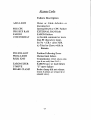
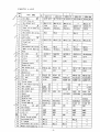
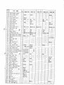
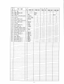
Tableof Contents
Section l: Lets get Started
Un-craung
h e l i m i n a r yS e r u p .
S i m p l eB a s i ch o g r a r n m i . n g
....
Com put erP r o g ra m m i n g....
Loading YuasaTerminal Program
Hand Held T erm i n a lPro g ra mu rg....
H a n dH e l d L o c k - u p. .
S im pleHook U p to C N C
UDIIC RemoteWiring Diagram
S t e pF i n i s hT y p e s
R e m o t eC y c l e S r a n .
Rem ot eCy c le F i n i s h
. . . .. . . . . I
.........1
.........1
.....2
. ..... .. . .2
........4
.....5
... .. .. .6
. .. . .6
.........7
......7
.....8
Section 2: LIDNC Panel Controls
FrontPanelSwirches
G-Codes
M-Codes
G-Code Descripriotr....
M-CodeDescripuon
....
Non-Motion Buffer Command
Input Data CommandsCharacrers .
SpecialandNon-MorionCommandDescripdons
Section 3: 'i' Parameters and Alarm Descriptions
' i" P ar am et ers
.
. . . . . 29
Section4: Trouble Shooting
My Computerdoesnot communicateto the UDNC
My CNC docsnor Communicare
to the UDNC
My Hand Held doesDot Commrrnicatewith rhe UDNC
Error CodeDefinitions
Dip SwitchConfigurarion
.....
Section5: Direct Operatioruthrough the RS-232
Fanucto IIDNC
Fadalto UDNC
M o r i S e k ir o U D N C
Ohlma to UDNC
Section6: YuasaTerminal Program
SystemRequiremens.
IrutallingYuasaTerminalro Computer..
RunningYuasaTerminal
T er m inalM ode
Y uas aE dit or
Section 7: Maintenance, Service, ui'Parameters, and Table Dirnensions
...44
.....46
.....50
.........50
.......50
.. . . . . 51
.. . . . . . 54
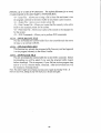
CREDITPOLICY
1) A ll r et ur n e dg o o d sm { s t h a v e p ri o ra u thori zati on.
The MR A (Merchandi seR eturnA uthori zati on)
N um ber
m us t app e a r p ro mi n e n tl yo n th e s h i p p ingl abel .P l ease refer to your ori gi nal i nvoi ce number w h en
r eques t i n g M R A ' s .Me rc h a n d i s es e n t i n w i thout a MR A # w i l l be refusedby our shi ppi ng department .
i:i ilir..=,-':l"".:-i:ii:i-,;ii.i: :.-i-.,!:,,:l*il-ili-,il.iiii.
2) Def ec t iveg o o d s w i l l b e re p l a c e d ,re p a i red,or credi tedto you :l i t* r the i tem has been i nspectedby o ur
S er v ic eD e p a rtm e n t;u n l e s sp ri o ra u th ori zati on
has been made.
3) M er c han d i s ew i l l n o t re c e i v ec re d i ti f: i t i s no l onqer under w arranty,has been mi sused,or has be en
alt er edo r d a rn a g e db y e n d -u s e r.
4) lf a unit i s d e e me dd e fe c ti v ea n d n o t re pai rabl e,credi tw i l l be i ssued.;.i 1,,:," ;i ' { j :+ ,-ii::;.i
-" ,,+ ;:i i * .r:,;i
i rq; : r : ;
l,"'i*i"i:i,:r.j',...Ji(':]..ii5..j.tl:-.':;:.:j;"i..i11,:':i;u;i".'j;.ji..,..i..j':.::
5) Any warrantymerchandise
thatis repairable,
willbe repaired
andsentbackto the customer;
therefore,
no creditwillbe issued.
6 )T h e r e w ib
l l e a 1 5 %r e s t o c k i n g c h a r g e o n a n y a ni tdeam
l l s n o t r e t u r n e d i n t h e i r o r ipgai nc a
ka
l ging&/or
not coveredby warranty.
7) No otherpolicy,otherthantheforegoing,
willbe authorized
or accepted
by YuasaInternational.
SERVIgEPOLLCY
1)Warranty
cardsmustbe on filewithin30 daysof invoicedatefora warranty
repair.lf warranty
cardis not
on fife, proofof purchasemustbe submitted
whenrequesting
service.lf neitheris supplie
d, all repairs
will be charged to the customer.
2) Therewill be a minimumchargeof $150.00for handlingand inspection
fee on all itemssent in for
inspectionif no defectis foundiwarranty)or if customerdeclinesserviceon unit(s)inon-warranty.)
All
"Freight
suchshipments
willbe sentbackto customer
Collect."
3) Unitsmustnot be previously
altered,repaired,
or serviced
by anyoneotherthanan Authorized
Yuasa
ServiceCenter.,4r,3,,*:t#ei! r',.ritiig:;i:f an ii*,;":*,rriiii:u::,;i'r*eriati:5r.
4) Beforeany itemwill be repaired,the customerwill receivea writtenestimatewhich must be returnedwithin
15 days, signed: Approve/Disapprove repair. ii:--i*f-.fii?*r_:;-:15-_lp:.::*ii:ii_ijr...jfI.'=t=
e,.:,,*i,iir,l=ii..:-ii.:_ilj:f
i.:i11,_li-:il:i':-.:::..i-:ii:l-l!-L5j-iji.i-i::::ii-';ii::r.-ji.;i,:;.!.=..:::':,.i-t9ilji|-r-i1]jrl*lt:i
1.:ii:t:.i..5) Afl repairs preforrneda the Yuasa lnternationalService Center: California,carry a 30 day warranty;
war r ant y l i m i te dto o n l y th e e x a c t i te msrepai redor repl aced.
6).:i--1.:,il"ii;.-::,-',.:
All repairscoveredas warranty,will have freightcharges credited
-.i:r-...:-.-i-:i'-,r::...i.,:"-j-:l::X-i..
bac k t o th e i r a c c o u n t.
GAUT|ONS
ANp WARNINGS:
We, Yuasalnternational,
arenotresponsible
for thefollowing
damagesor problems.
Adding & RemovingAccessories/Fixtures:
Whenattaching
or detaching
FacePlates,
Adapter Plates,Accu-Chucks,etc, the
Brakemust be in the clampedposition.
Failureto engagethe brakemay leadto
in thepositioning,
inaccuracies
unduewear
to gears,etc.
i. it;..;i,l i: i a i€ .:ii ig-.l]::iii--i,.:
.:li *ili,;iilr.:';,i--rt
j:i i!:i -!: iijii
ii-lil-:;' .:ji:i:: i,I :, | :r,i: -,l-,;i
J:i::,r:,t.
Use Filter- Regulator- Lubricatoron air lines:
You must use a Filter - Regulator
(FRt) in linewiththepneumatic
Lubricator
and Pneumatic
overHydraulic
brakes.lf
getsinto
water(condensation
or moisture)
the indexer's
brakecharnber,
it willcause
the brake(s)to drag and eventually
fail.
Waterand rustwill need to be removed
fromthe brakechamber.
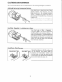
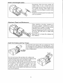
Avoid MotorGableDama
lncorrect
Setupthe Indexerso thatthe cableswill
not be rammedinto splashguard or
caughtin X-Y-Zaxistable. Failureto do
so can breaknot onlythe cablebut the
internal
wiringandleavethemsusceptible
to coolant,
metalshavings,
etc,
Correct
ill
Broken and DamagedCables:
Periodically
checkthe motorcablesfor
breaks,holes,or cuts. Coolantcan and
w i l ld a m a g ei n t e r n awl i r i n g{,e n c o d earn d
A/C power)causingmotor failureand
possibleAmp and MotionControlCard
damage.
Pleasedo notmerelypatchbutreplace
as
soonas possible!
Adjustment,Repairand Maintenance:
W h e na d j u s t i n gm, o u n t i n gr,e p a i r i n og r
performing
generalmaintenance
make
surethattheA/C poweris turnedoff and
preferably
removedfromcontroller.
Any and all serviceshouldbe preformed
off of the CNCA/MCand in a cleansafe
environment.
Neverlift,pull,or bracethe indexers
by
theircable(s)!
Avoid Tool Crashesand Over Torque:
Do not hitthe workpiecewithyourcuttingtool! This
candamageyourwormgearsandwilldefinitely
cause
youto realign
yourmachine
zeros,gridshiftsandlead
screwcompensation.
Do notovertorquethe spindles
withcuttingtools.
Thetiltspindlehasair-over-hydraulic
forrigidity
butthe
rotaryis usinga dualdiskpneumatic
brake.
lf youovertorquethespindle,
youwilldrivethe motor
out of position.Seemaxspindletorquefor yourunit.
A simple torque calculationprogramhas been
incfudedwith the softwarepackagein the folder:
YuasaTools,to helpdetermine
the amountof torque
y o uw i l lb e a p p l y i n g .
tv
Hitting & Modifying:
Do not hit the unit(s) body or
motor cover(s)with tools or
e qu i p m e n t .
Do not modifythe unitfrom it's
factory standards.
Any
alterations
willvoidwarranty
and
r e p a ip
r olicies.
KeepHandsClear:
Don'ttouch
while moving!
Do not touchthe rotaryor tiltaxiswhile
in motion. Make sure that all workpiecescanfreelyrotateand havetilting
clearance.
lf adjustmentsto fixture(s)must be
made,pleasestopthe unitandpreform
any necessary
setupadjustments.
Failureto complywith this noticecan
and may resultin lossof digits,hands,
andotherbodyparts.
MachineWisely!
Maintenance:
Oilshouldbe changedevery6 monthswitha heavy
dutyoil;i.e.:Valvoline,
Mobil,Quakerstate,
68 - Bg
weightGearOil.
Levelshouldbe checkedpriorto startup eachday.
The levelshouldbe filledTzwayup the sightglass.
lf any coolantor contaminate
is present,change
immediately.
lf motorcover(s)are removedor opened,be sureto
properlyre-sealthemwith an oil resistant
silicone
gasketsuchas Permatex
778 gasketseal.
Note: Clear silicone is not recommendedor
encouragedin a coolant& oil environment.
Section 1: LettGet Started
Un-crating
Thisis a fairlyminortask,yetan rmponant
one.Please
makesureyoumaintainthe
warrantycard,testreponandmanual,enclosed
your
packet.You wiil notice
in
informational
thatthe warranfycardprovidesyou with centerheightspecifications
of your table,andrhe
serialnumber.Savethis data,as it providesus with importantinformation,aboutyour
particulartableor indexer.As a precaution,we strongly recommendthat you maintain the
original crate for at least30 days.
helirninary Set up
After carefullyremovingboth the controllerandtablebody, placethemboth on a clean
table.First threadthe motorcableconnector,from the rotary lable,to the flange(,marked
motor) on the controller.Make surethat this and all connectionsare threadedn all the way.
Thenhookup thepowercableto an AC powersource,105Vto 125V.If you havethe 5CA
model, locatea clean(Filtered,Regulated-Lubicated) air line and affrx it to the small air
hose,leadingfrom the air colletcloserpiston.If you havean air brake,amachthe air hose
(w/pRL) to the fining. You are now readyto begin.
Simple Rasic Progamrning
This sectionwill only focuson simpleprograrns,
90 deg.,60 Ceg.,45 deg,indexing,
etc. Thereare threewaysto write a program:
1) Use your computer,with the softwaresuppliedby Yuasa.
2) Use our Hand-heldComputerTerminal(modelHCT-001or HCT-002).
3) The newestway, is to makeuseof the RS232port on your computerized
machining
center.As eachmanufacnlrer
is differentin their designandmacroneeds,w€ can only state
thatour controllgrrequiresthe abiliryto sendandreceiveASCII code.underthe following
conditions:
A) Minimum of 300 to a maximumof 19200baudrare.
B) Either 8 bit, no parify or 7 bit, evenparity Dau Transfer.
Note: Data stringscannot contain extra characters;{ie: #, Vo, < >./
C) A CarriageRerurn <CR> must be usedat the end of each Data strinq.
Line Feeds < LF> are isnoredbv the UDNC.
-l-
ASCII suing of commands,you can acruallyuse
a standard
Sinceour controileraccepts
any progran softwareyou havethatcan generatea programanddownioadthroughthe RS232
port. However,if you areusingrheYUASA TERMINAL softwarethe followingwill appiy.
r oading Program'
If you haven'talready,hookup your RS232cablefrorn your PC, to the RS232port on
the controller. Note: Thiscontroller usesa standardR5232cable.SomeCNC machinesusea
specialcablethat has pins#2 and #3 crossedto form a null'modem cable, if you usethis
null-modemcable,you will needa null-modemadapter.Nevecplugor unplug the R5232
cablewhen UDN{ or computeris en! Pleosecall if you needmore details.
/) Loading program. fnsertYuasaTerminaldiskeneinto drive A, thenrype:
beginto load the YUASA TERMINAL. l/ote: I{ot all of
NSTALL. This will automarically
the programs containedon the diskettewill be transferred,only thoserequiredfor Yuasa
Terminat. Otherprograms arefor separateoperationsand requireyou to enter separMe
I1VSTALLcommandsorfor you to copy them directly to your hard drive or work diskette.
2) Configure Screen.Confirm that the Terminal programis properly configuredfor
your computer.
You havethe choiceof using either
A) Com port. Is the correcrCOM port selected?
Com#t or Comf2.
pinlon.) Unlessyou areusinga PS/2sfylernouse,you probablyhavea mouse
pluggedinto Com#l. {DEFAULT = Com#2}
B) CardAddress.You havethe choiceof CardAddress0 -7. UnlessSpecifiedprior
to shipping,Card Addressis A0. {FACTORYDEFAULT = 0}
at baudratesbetween300 and9600.
C) BaudRate.As stated,you cancommunicate
{FACTORYDEFAaLT = 9600BAaD}
D) Dau Bis. Again,you havethechoiceof 8 bit/evenor 7 bit/oddparity {FACTORY
DEFAULT - 8 bit/even)
Timeoutthatsuitsyour computer.Older
E) Time Out. Selectthe Communication
1
486 andbenerwiil work w'ith
computers,
80286- 386,mayrequirehighernumbers.
=
defaultsemrng.
35}
{DEFAULT
Type uYn[o saveyour newsettings.The programwill thenconnectto the controller.
- Yes"is show whenylu are hooked-up
[,,lote:Checkto makesurethat 'MCC at A0 a^ddress?
to the controllervia the R5232cable.If you are not connected,checkyour Compofr, baud
rate, and makesureyour timeoutis appropriate.
3) You arenowin TenninaiMode,depress
[Fl0] EdiUCreateProgram,themainprogram
screenshouldappear.
4) Lets write our first program,(ltlote:Both YUASATELVIINAL and the controller
are entirelycasesensitive,all input must be in the conectformat) typethe following:
AOE
(makesureyou rypethe numberzero,not the lener "O", this addresses
the
cardandclearsthe buffer, this mustalwaysbe your lust entry)
Fi000
(This is the ma:rimumfeedrate.F1000 : L00%. Think of the last 0 as a %
sign.)
G90B90 (G90denotesan absolute
movement
and890 is a 90 degreemovement)
8180
(Thismovementis 180absolute)Onceyou haveinput a G90,the CPU
mainuiruabsolutemovements,
unlessyou changeit to incremenul(G91)
8.270
(270degreesabsolute)
M40
(This codeallowsthe CPU to readthe nextmovementin the program,in this
caseB0, andautomatically
seetheM30, resettingthe programandBlock# .)
B0
(IMorkzereposition)
M30
(Endof program)
If you would like to savethis progrurm
on the disk drive of your computer,depressthe tF2l
bunon,selectthe savefiie choice,(2), namethe file, andenrer. NelE: TheRemote/Manual
switchmustbe in manualmodeor the program will not he .stored.
Now downloadyour programto thecontroller,usingthe "F3" key (dumpto cardbuffer
andsave.) Note: 'Dwnld&SaveFile'[F3J will saveyour program, and all '1"parametersto
the card. 'DownloadFile' ff SJwill automaticallytakeyou from editor modeto terminal
mode,wherethe small 's" can be enteredto savethefiIe, if desired.
-J-
differentuB"movements,for
This programformatcanbe duplicated,substiruting
By simply
wouldbe 60 degreemovemenrs.
860, glz0, B1g0,F;240,8300,80,
example
u-"
you canmovecounterclockwise'
in front of the B movement
insertinga minussign
like
thesesimpieindexmovements,
Therearea numberof otherwaysof accomplishing
usingttreloop (GZ0)function,bur for a quick start,this is the easiestway to begin.
Ila'td Held Computgr Terminal Prog"aming
ro the LIDNC controller,pushthe [ON bunon.The screen
Wirh the HCT connecred
to the [F] key andyou
shouldsay "HOST FOUND." hrsh the (oK) bunonwhich corresponds
will be in the yuasaMenu. You will find the foilowing list of options:
OFF
GurnsHCT off)
File Manager
(Takesyou to files that are storedin your handheld or
'S" are
letsyou write files. l';lote:Filesmarkedwith
paruneterfiles and ?" are programfiles. If you choose
the pararneterfiles that do not matchlour unit, your
table will not ntn correctlY.)
New File
(Createfrles to run your index and storethem in the
HCT.)
Terminal Menu
(DiagnosticandMDI operations.SeeHCT manualfor
furtherexplanation.)
heferences
(Letsyou confrgureyour HCT for specialapplications.
Note:thefactory defaultis A0/9600/8bit/even.)
Card Status
of controllersMCC functioru.)
(Usedfor checkings13rus
Select[CreateFile] by usingthe arrow keysto highlightthe namepresstOKl. You will
now be at a compietelyblank screen.Pressthe [a] key locatedbeneaththe [ENTER] bar. The
a shouldnow be seenin the top centerof the screen;if not pushbuttonagain.During
programming this hutton must he active.Pushthe [ENTER] bar aftereachline entry. Lets
write your first program.
A6E
(Lower caseletters needto havethe Purple..-pushedprior to the letter.
A0 = Card Address& E = ClearBuffer.This mustalwqs start every
presrsru)
F1000
(Thisis the maximumfeedrate.F1000= rcT%. Think of the last0 as a %
sign.)
1-
movementand890 is a 90 degreemovement)
G90890(G90denotesan absolure
B1 8 0
(Thismovement
is 180absolute)Onceyou haveinputa G90,theCPU
(G9l)
unlessyou changeit to incremental
movements,
absolute
mainrains
F.270
(270 degreesabsolute)
tYI40
(This code allows the CPU to read the next movement in the prograrn, in this
case80, and auromaricallyseethe M30, resettingthe program and Block # .)
BO
flilork zeroposition)
M30
Gnd of Program)
Irlow push the [cr]key againand the IENTERI bar. You will now be at a screenthat hasthe
pilesthqt haveP##X2are
-cursorflashingbehindthe lener "P". Note:P PregramfiIes.
parameters.Type the nameof the file we havejust created:four andpressIENTER]. You
shouldnow be at a screenthatsays:EDIT, Download,Dwnld&Save,andPrevious.If you
are still connectedto the TIDNCandthe unit is on, select:Dwnld&Saveto transferfile and
saveit in the UDNC.
'
l{ote:The Remcte -ual switchmusthe in manualmodeer thef'ogram will not be
stored.
Fand-held T ock-rrp or No Yuasa Screen:
If you are no longerin the YuasaPrograrnor your hand-heldstopsreacting,here's
whatvou needto do:
1 ) F,rshthe [ON & tC] buttonsat the sametime.
z)Confirm thatthe screennow lookslike this: {HOME} in the upperleft of screen
it. And theblackboxes
wirlr the#'s 4,3,2, 1 runningdownthescreenbeneath
I etc.
containReal/vector/base
3) hsh the pARl key andtheboxeswill now contain{YUASA/MCC1/TIME/eIc}.
Pushthe buttonthatis directlvunderthebox thatreads:IYUASA].
4) The "NO HOST"screenshouldnow appear.If not, pleasecall the YuasaTechnical
63.
SupportDept at 800-,121-97
NotezIf leur handheldgivesqk'w batter! warningde not ignereit, if the hatteriesdie or are
remevedthe unit can enl:thold memoryforeboutten minutes.
-5-
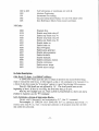
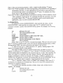
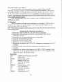
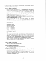
SimpleHook Up to your CNC MillinL\fachineMachining Center.
Warning: If you are not an electricianor havenot interfacedan M-function
product before,We stronglyrecornmend,havinga qualifiedelectrician,do this
installation.It's like anythingelse,it's easyif you know how, and very dangerous
if you don't.
Suppliedwith your new rotary is what we classifyas a remotecable.On the backside
of thecontrolleris a L4 pin socketlabeled:RENIOTE.You will noticethaton end of thecable
is a plug, this matchesthe statedsocket,andon the otherend are 13 loosewires. Thesewires
haveseveralfunctions, as shownin the electricalschematicdrawing, but for this quick
interface,we will only concernourselveswith the rwo cycle startwires (,#2and #3 which are
hlack& green)andthe two cyclefinishwiresff 4 and#5 whicharered/white& orange).
Unfornrnately,machinetool buildersdid not get togetherwhenthey were buiidingtheir
equipment,and as suchprovidedus with no commonaliryto developa singleinterface
drawing.What I can offer you here(in additionto our electricaldrawing)are somehints,on
how to acconplishthis task.
Warning: When installing the RemoteCable, pay very closeattentionto
. (Redmay look
very much like Red/White)Connectingthesewires incorrectlycan createa very
expensive& extensiYe
repair.
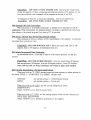
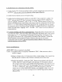
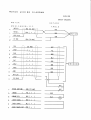
Note: Before beginning this interface, compareour electricalschematic,with yoar CNC
machine'selectricaldrawings,for actual signal information. All machinesare dissimilarand
may needto be installed differently.
UDNC
REMOTE
PORT
CNC MACHINE
n'd.f
.
.
M-codc Strn
+tr4VDC
tr.,o gU.1!-L
M-Co&
Flnlrh f l
+2rVDC
lX.Q.crd.C.l
M-Co&
Flnirh f2
Eracrgcncy Stop (N.O.)
Fccd llold (N.C.)
Rernotc Homc (l!l-<odc
or othcr clrcult)
* = No Voltage can ever he-applied to these lines without damaeing the internal circuitry.
-6-
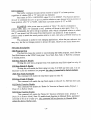
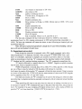
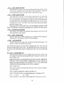
S t e pF i n i s h T y p e s
B a s e do n S t e ps t a r t t y p e s :
Tlrpe A (No Step Finkh)
Remotestep
l-
Rotation
Remotefinish
t_
I
Type I No Handshake)
Remotestep
j-l
l-l
Rotation
Remotefinish
I
ll
t_
j-l
t-t
I
l.-
Type 2 (Handshake by remote step input going active)
Remotestep
I
Rotation
Remotefinish
t_
l-
l_
l_
Type 3 (Handshakeby secondremotestepinput going pass
ive)
Remotestep
l-l
l-l_
Rotation
l-l
lRemotefinish
l-
T)'pe 4 (Synchronous Start)
Remotestep
l-l
l-l
Rotation
ttt-tt-l
Remotefinish
l-l
l-l
l-l
l-l
1) Determinefirst, where your M-code is outpuning. If you're lucky the M<ode has been wired
out to a tenninal strip. If you are very lucky, your CNC rnachinemay also have included a
relay for the M-code output.
2) If you are one of the extemely lucky people that have a relay already installed, sirnply hook
wires #2 and #3 of our remote cable, to the normally open conLactson the relay, or [o a
terminal strip, if there are already wires running from the relay.
3) If your machinedoesnot have this indexer M-code reiay, you may needto irntall one. On mosr
machinesthe M-code output, acts as a switch for a completedcircuit, but some,ourputvolLage,
either24V DC or 110V AC.
or 110VAC,
4) When addingthe relayyou mustf,rrstdeterminewhetheryou needa24Y DC
of reiay,
rype
checkyour machineelectricaldrawings.Thenmakesureyou havethe correct
as somemachinesalreadyhavea receppclein place.
the M-codeoufput,
5) If your machinesM-codeourpumvoluge, say 24Y thenrun a wire frorn
plug, to one
eitherfrom a terminalpoint,oi to*.times from a pin on a connector,like a Honda
another
sideof rhecoil on therelay,(normallypin #7 and,#8,but checkwith your rneter)Hook
wire from tfie othersideof the relay coil, to ground.
Run a wire from the M-code,to one
6) If the M+ode ourputis a switchrypeQikemostmachines)
sideof the coil, and voltage(normally24Y DC) to the otherside.
the
?) Thenalwaysconnectwires# 2 and#3 ofthe remotecableto the normallyopencontacts,of
relay,againcheckwith Yourmeter.
(pO l'/OT
Note:To simplify this: Our machinerequiresa contactclosureon wires2&3
AppLy vOL* GE..Iparaneter i32 is programmableto the typeof handshakingthat most
mnchinerequire.
Remote Cycle Finish
The way rnostmachineswork, oncethe M-startis initiatedthe rotarytablecontroller
will executethe next stepin the program,driving the tabteto the desiredposition.Oncein
position,lhe rotary encoderverifieslocationandeithera contactclosurewill occur, (if
usingnorrrally opencontacts)or a contactopenwill occur,(if usingnormallyclosed
utilizenormallyopencontacts.andoperatewith a
contacts;.Most CNC machines
or 1.0 sec.)
rnomentary
close(either0.5-Sec.
Again, it is imperativethat you consultyour electricaldrawingsfor confirmation,
but if your machineis lookingfor opencontactson the returnsignal,you would hook wires
# 4 and#5 on our remotecablero + 24V DC andthe M-Finishon your CNC machine.
There may be a numberof differentconfigurationsto this formula. If your machine
with
needsnormallyclosedcontactson the renlrn signat,if so pleaseverify all connections
the electricaldrawings,or contactyour machinebuilder.
Ir{oteLz To simpltfy this: Our machine givesa contactclosureon wires4&5.
potaritypleasecheck 'i" parameter#32.
Note 2: For thefinish type/contact
For the delaytime check 1" parameter#31{Default for i32 is 2:0}
-8-
Section2: L|DNC PanelContr"ols
Front Panel Switches
1. On and Off, be sure to check rncomingvoltage,prior to powering up. The off
switch, totally shun off the entire system.Program memory and work zero position are
connect or di$cennectany ol the cahles while UDIVC i,son!
stored in EARO\v1r IT{ever
2. Program Select,is usedto accessboth the Main ProgramOf), and the sevenadditional
(0 -6.) Theseprogramsare recognized,when either the M30, W-Z set, or W-Z
programs
sub
retrun switches are seenor by simply changingthe selectorswitch to anothernumber setting.
(You must be in Manual Mode when you changeselectorswitch.)Selector
switch .,vr"
performsa go to the beginning of the main buffer program. Programseiectorswitch 0 - 6 does
a go to the beginning of subprogram L0 - L6. It is readand usedwhen the W-Z set,W-Z return,
areexecuted.It is alsoreadwhen the program
Machinehome,Poweron, and the M30 corrunanCs
blocknumberiszero.If no subprogramexistsfor the program selectorswitch. then the main
buffer prograrn will be nrn
Note: To simplify this: The proces.sfor storing more than one set of indexer
commands is to wrile one main progrun that contains up to 7 subprogrun, which will fill
the 8 positions on the selector switclr. {See Sub-Prograrns}
3. Jog * , Jog -, the jog feedrateis controlled,either by using the Feedrate
+
Override, or changingttre value of i09.
4. FeedrateOverride, controlsboth thejog feedandthe programfeed.This
functionoperatesin 10%senings,basedon the valuein i06.
5. ManuallRemote.
Manual Mode: is usedfor operatingthe front panelswitchesand for useof the
pulsegenerator.
ln this mode,the brake will be disabledand no remoteI/O will be
accepted.In addition,the autosteppingfunctionwill be enabledeitherto a block numberor
tfuoughthe progrzlm.A CycleStart will causetheprogramto stepthroughthe each
programmedmovefor eachCycle Start input.
Note: To usethe brakewhile in manualmode,set 't72'to l(on), then the pressing
of CycleStan will turn off the brake, index the machine,re-enablethe brake. All other
buttonswill act as if in Remotemode.PulseGeneratormust be discoxnected
tf yoruselect
this optionor severedamagete hrake_andmotof will eccur.
RemoteMode: the following front panelswitches$V-Z set.W-Z rerurn.Jog+
andJog-.Cyclestart.andFeedhold)will be disabled,
andtheremoteI/O, will be enabled.
The homingfunctionfrom the front paneiwill be disabied.Remote,requiresa rernotecycle
startto executeeachprogramblock.Goingfrom manualto remote,will causetheirrogram
to sropat rhenextprogramblock.
-9-
6. CycteStart/IvI-ZReturn: The cycle startbunoninitiatesa stepstart. Each
of rhisbunonwill cyclethe rorarytable,oneindividualmovement.To initiate a
depression
MachineZero Return M-Z), you must depress,ild hold the cycle start switch for 5
seconds.This will beginthe searchfor the "C" channelof the encoder,which is classifiedas
MachineZero.
Note:On 5C, sCA, and 132 modelsyou must first jog to within four degreesof
home,and then depress,and hold the cyclestart switchfor 5 seconds,This will beginthe
searchfor the t" channelof the encoder,which is classifiedas Machine Zero. These
units TIome' at every4 degrees,
7. W-Z Set: This Work Zero setbufton,setsthe currentpositionof the rotary unit
as work zero.Onceyou have depressed,this button, any previouswork zero settings
will be lost, and the controller will recoguizethis new position a work zero. Thisswitch
is enabledonly in the manualmode.Typing "Z|n the terminalmodewiil performthe
motioncard'suZ" command.
of this bunonwill rerurnyou to the currentwork
8. W-Z Return: Onedepression
zerosetting.It witl also causethe motion programto go to the begiruringof the prograln,
by ttreprogramselectswitch.This Switchis enahledonly-inthe manualmode.
selected
this buttonautomaticallysetsthe feedrateto zero,
9. FeedHold: A singledepression
stoppingall tableandmotor movement.Movementwill resumeby pushingthe Cycle Start
once.
10. E-Stop: Emergencystop is usedto totally stopall movementandshutsdown the
controller.As before,work zerosettings,programsanduinvariable'sare storedin
EAROM.
M and G Codes.
The programmingof this controllerutilizesstandardM and G codes,found in
corrmonCNC MachineTool controls.Belowis a listingof thesecodes,andtheir meaning.
A moredetaileddescriptionfollows.
G-Codes.
G04
GL7
G28
G30 to G39
G70
G7L
G72
Dwell.
TerminateSubRoutine.
MachineZero.
Jurnpto Subroutine.
StartLoop.
End Loop.
Auto Divide.
-t0-
G80 to G89
G90
G91
G92
G93
Call Subroutinesor conditionalcall with @.
AbsolutePositioning.
lncrernentalPositioning.
Circular InteqpolationRadius,(for use with linear table)
Zerc ReferencedMoves from secondcoordinate.
IVI-Codes
M00
M18
M19
M20
M2I
M22
\23
M30
M36
M37
M38
M39
M40
M41
M42
M43
ProgramStop.
Disablestepfinish relay#1
Enablestepf,rnishrelay#1
Disablestepfinish relay#2
Enablestepfinish relay#2
Disablebrakeon.
Enablebrakeon.
End of Program.
Enablepulsegenerator.
Disablepulsegenerator.
Enablebacklash.
Disablebacklash.
Enablecontinuousmotion.
Disabiecontinuous.
Enablemirror image.
Disablemirror imase.
G04, Dwell (T digrt.s.1 to 8388607millisecs:
A C'04X1000
wouldcausethe axisto remainin positiononesecondbeforebeing
readyto executethe nextblock. A G04 requiresa stepor rub cornmandto be execured.It is
a block of datathatcausesthe "In position"registerto reportfalseduringG04 execurion.
Note #l: G04 dwellsare not affectedby '% ". The dwellperiod startsat the
beginningof decel.If decelis verylong, the dwell time may go to zero.
Note #2: For multiple axisuse, when a dwell is proportional to a movesizeand a
feedrateis required, usethe W'command.
Gl7, Terminatea Group ofsuhroutine Blocla.Startedwith L0 throughL9 andterminared
by G17. (See"L" command)
For example:L0 G04X500M19 G04X1000GL7is a subroutine
thatdwellsa t/z
second,rurnsrelay#1 on, waits1 secondandcontinues
at rheprogramstepaftertheG80
thatcailedthe subroutine.
-11-
G28, Go to f{orqePositionftl-Z Refurn)'
04.If
programcon|rol,and as specifiedby initializeparameters,i02, 03 and
t.Jnder
WhenG28 is issuedand i04 is non zeto,the
iftl is zero.homecommandis disregarded.
is seen.It thenlooks
servowill movein the direcrionrp..ifr.o by i02 until the homeswitch
the i03
the controlexecutes
Whenthe "C" channelis detected,
for theencoder,,C,,channel.
the homingprocedure'
move,terrninating
it
Note: On-SC,sCA,and 132the rotarytabledoesnot havehomelimit switckes,
to first jog the tableto vernierzero,prior to executingG28, or the M-Z
wig be necessary
automaticallyMachinezeroposition.
functionon the controlpanel. This positionis
G30 to G3a, .Iumpto Subroutine.
This conmand is similarto G80 (Cail) exceptthat it branchesto subroutinesL0
the programis terminatedand the
throughL9. When a G17 or M30 is encountered,
progr"- pointeris rerurnedto the beginningof the subprogram-G30jumps to subroutine
L0, G31jumpsto Ll, etc.
canbe madeconditionalby usingthe "@"
In addition,both G30 andG80 conunands
u@"conmanddescriptionfor details.
conditionalcomrnand.Referto
The form of rheconditionalJumpandCall are respectively:[email protected] and
[email protected]
or port, 0 to 65535,andB is a bit, 0 to7. Thesecommands
WhereA is an address
allow the Jumpor Call to be madebasedon the conditionof an input at the specified
address.
G70, G71 Start and Fnd I oop
GT0XNNNNN(5 digits)0 to 65535.0 infinite.
All blocksberweenG70 andG?1 commandsareexecutedas manytimesas specified
in G70 command.
FXTVIPLE (a):
move180
AOE G70X15 F1000 Gg1B180 G7L M30 : Unit will incrementally
degrees15 times.
FXAMPLE ft\:
of 90
AoE G70X0 F1000 GglBgo G7L M30 = Unir will movein increments
degreeswithoutan addttionalstan signalat the endfor the M30 command.
Note: A looping commandma! nptrbe usedinsidea loop. Thefirst loop will reiect
the statementi7 trtondary loop command.(SeeL0 to L9 for-ntles governingloops
and subroutines.)
G72 AutomaticDiYide
GTZXNNNNN(5 digits)2 to 65535.
This corlmandwiil instructthe unit to divide[he nextmovementcommandinto the
numberof equaldivisionsyou require.The divisiontakescareif residualencodercounts
andthatthelast
erroroccursduringincrelogntation.
andinsuresthatno cumulative
correctly.
wiil execute
movement.
-12-
EX^{VIPLE: AOEF1000 G72X10 G918360 NI30.This programwouldevenly
In this
of 36 degrees.
divide360degrees10 times,producingindividuaimovements
caseoneadditionalstartcornmandwill be requiredat the end of the M30.
To eliminatethe needfor an exra surt command,write rn an infrniteloop.
EXAMPI tr: AOEG70X0F1000 G72Xl0 G918360Gl7 N[30.
G80 through GSq[Call) Suhroutines
Will executeup to 10 possiblesubroutines,
asdefinedby L0 ttrough L9, (see"L"
the programpointerwill jump to specifiedsub-routineand
conunand.)Whenencountered,
thenrerurnsto the normalprogramflow whena G17 is executed.
This coslmand is seenas a default, if G91 (incremental)is not initiated. An absolute
movementthat is relative to zero.
EX'ryrlrl.nt AOEF10008180 B.270M30 = Move therotarytable,first to 180
degrees,thento 270 degrees,
all referenced
from zero.
Ga l SelectsIncrementalData Positioning
An incremental
move, is onethat is relativeto the currentposition,not the zero
location
FX^MPLE; AOEF1000G918908180 M30 : Firstwe wouldmove90 degrees,
thenan additional180degrees,
from the 90 degreeposition,a total270 degrees.
Note: G90 and GgI are modal commandswill remain in effect until changed.
Gq2 Circularjnterpolation.(lForlinear applications)
Whenusedwith an "X" t58H], presetspresentpositionregistersto valuesselected
in
this block. [G92X +/- NNNNNNN] 0 to 8388607encoderlines.
G92X1000
G92XO
setscurrentposition- 10000EncoderCounts
setscurrentposition= 0 [zeroset]
When used with an "R" [52]Tl, setsthe circular interpolatiiinradius,
G92RNNNNI{N.
Where: NNNNN is 0 to 262139encoderlines.
When usedwith a "C" [43H1,setsthe startingangleat which circular interpolation
will be rnade,G92CNNNNN.
Where: NNNNN is 0 to 360000in incrementsof .001 desrees.
- 13-
Go3 Cornmand
u0"or homeposition,
movesrelativeto initiai
This buffercorrmandexecutes
of whetherG92or "Zn (zeroset)wasexecuted'
regardless
permits
The formaris G93+/-NNI.{NNNNwhereN is 0 to 8388607.This tunction
positionor
the userto conunandthe servoto go to a positionrelativeto zero[powerrurn on
homeposition,after"hnor "G28"],ratherthana positionrelativeto "2" or G92.
EXAIVfpIF: After powerrurn on, positionis "Zero."If a moveis executedto
position2000,thenauZ commandis sent, positionwill be setto zeroagain.Now, if a
rhe senrowill go to position1500,which is displayedrelativeto where
G93 is corrunanded,
the,,2, was issued,but 500 countsfrom wherepowerwasrurnedon. If the displayed
positionneedsto matchthe acrualpositionrelativeto zero,thensenda G93500followedby
a G92500.
wherethe part referencezero
This commandis usefulfor tool changingapplications,
may vary, bur the tool changepositionis alwaysthe same,relativeto the initial homezero.
M-Codes description
M00 Program StoP
This functioncausesthe control to stopexecutingthe buffer program, much like the
FeedHold bunonon the UDNC front panel.Use a Start,Run, Step,or Rub Out command
to resumemotion.
M18 StepFinish#l Disable
Writing this codeinto a programblock will disabiethe stepfinish signalon relay #1.
Mlq StepFinish #1 F nahle
Writing this will enablethe finish signalon relay#t if M18 hasbeenused.It is not
in a program,the relay is turned on by factory default.
,o put this statemenr
necessary
M20 StepFinish #2 Disable
This corrmandwill disablethe stepfinish signalon relay#2.
M21 StepFinish #2 F nable
This corrunandwill enablethe stepfinish signalon relay#2 if a M20 hasbeenused.
V[22 Brake FunctionDisahle
This commandwill disablethe "BrakeOn" functionin Remotemode.{Defautt
Brake On in RemoteMode]
M23 Brake FrrnctionEnable
:
This corrmandwill enablethe "BrakeOn" functionin Remotemode. {Defarlt
Brake On in RemoteMode) l,lote: To enablebrakefunction in Manual Made, pLrameter
il7 needsto be setto a valueof 1. ThiscommandwilI notfunction in Manual Mode
unlessthe aboveciteria is meL
-14-
NI30F'ndof program
andcarriagererurn.
by an M30 corrlmand
All wrinenprogramsmustbe terminated
The M30 instructionis intemretedtwo differentwaysby the UDNC:
1) If theprograrnconsistsof lessthan448 blocks,the M30 will resetall "M"
functionsandfeedrateirurn:ctionsto theirdefaultvalues.It alsosetsthe Drosramexecution
pointerto the beginningof the programthat is storedin the buffer.
2) It the programis largerthan448 blocks,the M30 will resetandpurgeall
functionsincludingthe programbuffer.This requiresthatthe hostcomputerretransrnitthe
programbeforeprogramexecutioncanbe surtedagain.The inittaltze"M", "G", and
Feedrateinstnrctionsare not reset,andneednot be reloaded.
N{30 Rules
RuIe #l: A pro$am withoutan M30 cannotbe savedin the EAROM perrnanent
mernory.
Rule #2: When a programis writtenandterminatedwith the M30 instruction,a new
programcannotbe wrinen unlessthe buffer is cleared,usingthe uz"or "E" command.
RuIe #32An M30 requiresa cyclestart, unlessthe moveor movesbeforeit havea
preceding.
M40
{SeeM40}
M36 EnableSerialPulseChannel
(SPG-100or LPG-200.)
This codewill enableuseof the optionalpulsegenerator
The pulsegenerator(handwheel)port will autornatically
be activated,andableto be
accessed,
oncethe'Manual/Remote"
panel
front
switchis positionedin the manualsetting.
This will alsodisablethe brake,allowingfor instantuseof the pulsegenerator.
{Factory
Default)
M37 ftisahleSerialPulseChannel
This codewill deactivate
port on thebackpaneiof the controller.By
thehandwheel
defaultthe handwheelport is setas acrive.
M38/lV13o
Enahle/Disahle
Backlash
As specifiedin the i05, backlashparameter.
Defaultis 1600givingyou approx.:1
degreeof backlash.To activatethebacklash
fearure,theM38 mustdirectlyfollow theA0
line at thebeginningof the mainmotionprogram.If Backlashis desiredfor all of the
desiredprogram,thereis no needto addtheM39 statement,
if will be automaticaily
disabledby the M30 commandat theendof the program.
M40/M41Enahle/Disahle
ContinuousMotion
This codemustbe usedwhenit is desiredto automatically
executean lv{30
colTlmand,
withoutthe needfor a separate
cycleinputor to performHelicaloperations.
-i5-
F'x{MPLE: AOE F1000 G908908180 }I40 B0 M30
Wirh rhisprograrn,the controllerwouidknow thatafterthe B0 [work zero]block
readthe M30, withoutthe needfor an additionalcycieinput.
to immediately
wasexecured,
lv{00and M30 are the only two M-codeswhich requirea cycie, or rub cornmandfor
execurion;rhereforerhe needto urilizethe M40, prior to the lastprogrammove beforethe
M30.
unusuaimotionprofiles,suchas
Anotheruseof this functionis for generating
hyperbolic,parabolicor arbitrarycurves.This commandprovidesa continuousmotion
string,blendingdifferenrprogranmedmovesandfeedrates,with one simplestepstart
corlmand.This is extemelyusefulif you are aftemptingto developa heiicalmove,
synchronizingan "X" axis movewith a rotationalmove. Many timesthe lead,or pitch of a
the needto alter the rotary feedrateand
panicularpan cut will change,necessitating
movementwithout stoppingfor anotherstepstartconunand.The movementsand feeds
enreredbenveenM40 andM41 will executein a continuousfashion,permittingthis rypeof
move.
F{ALIPI F': AOE M40 F500B90 F250845 F100830 M41 M30
a delaybeforea movebegins,as
is to generate
A commonuseof theM40/41conlmands
follows.
Note: The M41 doesnot haveto be there, program will finish at M30 and resetwithout
M41. If you want to give a secondstart commandto resetprogram then use as above.
M42l]Vf43Mirror ImageEnable/T'tisable
This codewill causeall programbuffermovesJo occur in reversedirection.The
controllerwill outputa negativesignalfor everypositivemove, it executes.On a two axis
machine,this featurepermitsa part to be duplicatedin all four quadrants.Note that all "i"
will executeindependently
of M42, Homedirection.offset.andbacklasharenot
f'a.arneters
affectedby M42. Only motionbuffer movesaremirrored,includingG92, C, u andother
movecofilmands.Circularmovesare alsomirror imaeed.
Non-Motion Buffer Control Commandl
^
^Q
S
^U
^V
$
%
=
't
E
H
I
B on - turnson RS232Ctransmission.
B off - rurnsoff RS232Ctransmission.
Unfreezeposition,followingerror time click, no addressing.
Freezeposition,followingerror, time click, no addressing.
Reset
Feedrate% Override.
Rerurnto pre-jogposition.
Sendstatus.
Purgebuffer,prepareto acceptnewprogram.
Feedhold (stop)
Inn sendmotionparameter.
- 16-
I
O
a
R
S
Y
Z
b
c
d
e
f
h
i
j
k
I
p
r
s
t
w
X
z
Jog+
OurputDAC value.
Stop.
Run.
Step.
Sendcurrentposition.
Zero set.
Go to beginningof. This fi.rnction
is similarto the "bn"
cornmand:go lo the beginningof program.
Copy RAM to EAROM.
DownloadEAROM to RAM.
Senderror code.
Sendfollowingerror.
Home.
Inn sendstoredparameter.
JogKill servo.
Irarn posirion.
Sendcurrentposition.
Sendmemorydata.
Saveprogramandparameters,
in EAROM. Must be entered
in terminal mode.
Self test.
Write memorydata.
Sendtime click.
h:rge buffer, prepareto acceptnew program.
Input ltata Command Characters
Backspace
CR
CNTRLX
Space
Comma
Period
Slash
Colon
Back line pointer,onecharacter.
End of line character.
Cancelinput line.
Separation
character.
Separation
character,conditionaljump valuedelimiter.
Conditionaljump bir delimiter.
Commentdelimiter.
uIJ"commanddelimiter,"i" Valuedelimiter.
-17-
Special,and Motion Commands
fn or XlSingle AXIS tllotion.
our usewill be for
This commandis usedas an axisidenrifier.For mostapplications
but this controllercanalsobe usedfor linearmoves.For eitheraxis
roury movements,
linearmoveusing"T" insteadof
or 82.5000(2 1,12"
i.e., 8180 (180degrees)
movement,
uF") we utilize the "B or X" for the movement.
For a reversedirecdonmove,simplyinputa minussign,i.e., B-180,wouldbe 180
direction.
degreemovein the counterclockwise
(4 leedrate Setting
of feed,basedon the value
The (F) setringin the program,actsas a percentage
setringof parameteri06.
For example:F100 setsthe feedrateto 10%, of the maximumfeedrate,valueof
to LjO% of i06. Think of the last0 as a % signi06. F1000would setthe feedrare
The'F" commandis modal.aqdwill remainiq effectuntil changed.
(.'I)Time Mode Fogramming
Where:NNNNNNN is 1 to 8388607in millisecs.
This commandmay be usedwhenevera specifiedmove time is desiredratherthan a
feedrate.Ia primary use in the controlleris if a timed prograrnmingis usedon multiple
of the move sizeson eachaxis, all moveswitl terminatesimultaneously,
axis, regardless
thereby,providingan 8 axis linearinterpolationcapabiliry.
with time
Feedrat.uF" programming,whiCtris modal,can be usedinterchangeably
nTnin anyprogpm.Caremustbetakenjore-speci?thedesiredfeedrate
bYf'lacin9
programrning
in the profam immediatelyafterthe last"T" move.
zur"F" co.mmand
In uT" mode, the automaticbacklash(M38 fM39) is not permitted.
The time round off errorfor very small andslow movesis tradedin favor of velocity
throughoutthe
roundofferror.Thispermitsmultiplecontrollersystemsto remainsynchronized
full dynamicrange of the controiledoperation.
equivalentto 200encodercounts,for a 2
Thevelocityround-offis small,approximately
countsh wo hours,it will terminate
hourmove:i.e. if you tell thecontrollerto move2,000,000
countmoveat the very endof the
themoveexactlyon time,but maymakea 100to 150encoder
themove,thuscreatingasmall velocityjerk. Time and
time period,insteadof equallyspreading
This errorrapidlydiminishesasthe movetimesbecomeshorter.The
positionremainaccurate.
velocityerrorof % of an encoder
wouldhavean undetectable
sarnemovemadein 20 seconds,
count.
uT" Yalueof 2014
Time Constant:1 secondis equal to a
and
If you wanredto move360 degreesin 1 minutes,you wouldhrst multiply60 (seconds)
2Ol4 whichequals:120840.Your "Tn valuewouldappearas T2416808360.
-18-
HelicalTime FeedFormula:
To figureout whatuT" valueto usefor a helicalcut, usethe formulabelowor usethe
TMEIvIODE programlocatedon theYuasaDiskette.
the Radiusof theWorkpiece.Radiusis equalto ttredisuncefrom rhecenter
1) Determine
of tlre workpieceto it's outeredgeminusthe depthof the cut. {If you measureyour
wor@ieceto be 4" in Radiusandyouare doinga I/2" cut,your Radius= 3.5")
This is R.
2) Determinehow far you wantthe workpieceto rotate,{i...: 45 degrees.}This is D.
is goingto be, {i...'. !2".} This
how far theX axiscut acrosstheworkpiece
3) Determine
is X.
4) Determinehow manyinchesper minuteyou wantthe workpieceto travel, {i...:6".}
This is fPM.
5)Tt'R'D = I
180
6)
(fi:3.14t5926536)
It+xt
'
7) 120840
L- ' : f
IPM
Usin&the eramples stated we will figure the Formula as follows:
3.1415926536
X 3.5 X 45 I 180 = 2.74889
2.7488* + 122= t2.310824
12.310824X 120840I 6 - 247939.98or 247944
Your programed
"T" valuewouldlook like this:T247940845
Note L: In T" mode,the seno computesafeedrwe basedon the specifiedtime, and the
sizeof the movefor eachblock of data.
Note 2: The T" modeis a modalclmmand and takeseffectin the block whereit appears,
and remainsin effectuntil another T" or 'F" commandis given.
Note 3: Caremust be taken to specifya T" time which will result in a feedrfie within the
machine'scapability.Othertvise,a PositionFollowing error will be generated.
- 19-
'T" moves.
Note 4: The acceland decelparameter,('108'), remain in effectduing
Note5: The T'time specifiedis the timefrom beginningof accelerationto the beginningof
deceleration;therefore,in someapplicationsit is necessaryto make allowances
for the decelttme which is not includedin the T" move. To calculatedeceltime,
pleaserefer to '108'parameterdescription.
N o t e 6 : If a 'T"time is specrtedwithout a net motion occurring, it will be treatedas a dwell
'G04" command,erceptthat the 'qoncommandwill alter the dwell time. (SeeG04
forfurther details.)The T" time dwell shouldbe usedin synchronizedmotion
applications,sinceit is more accuratethan the Ga4.
C Circular Move.
ln conjunctionwith the G92RNI.{NNNNN,which specifiesthe radius,and the
which specifiesthe startingangle,the "C" comrnandcausesthe
G92CNNNITINNN,
velociryprof,rle.For example,the following
controllerto executea motionwith sinusoidal
program:
the card.
addresses
setscurrent positionto zero.
clearsbuffer.
zorE
setsthe feedrateto L00Toof the "i06" value.
F1000
G92R10000 setsthe radius to 10000.
setsthe starting angleto zero degrees.
G92CO
end of program.
M30
Senda "Rub"or an "S" or an uR"to executetheprogram.Witl movethe servomotor
from u0"positionto 20000encodercountswith velociryreachingmaximurnpeakat 10000.
Havingreached20000,the rnotorwill reverseandrerurnto zeroposition.
To makethe motor go to -20000andback to "0", specifya startingangleof 180
degrees
by changingG92C0to G92C180000.
The rangeof G92Ris from 0 to 262139encoderlines;and G92C is from 0 to
of resolution.Both the radius
of .001degrees
or 3.6 arc. seconds,
360000,in increments
power
or reset.Oncespecified,the
nlrn-on,
to
zero
on
and the startingangleare initialized
radiuswill remainat its specifiedvalueuntil changed.However,the startinganglewill
changeincrementallyas movesare executed.For example
, if G92C0is specifiedanda
(90
will
now be G92C90000,for the
the
angle
degrees)is executed, starting
C90000move
next move.If a differentvalueis required,it mustbe enteredinto the prograrn.
The "C" conmand'srangeis from 0 to 8388607and, therefore,aliowsup to 23.3
line. The useof a loop (G70)corunandallows
to be executedin a cornmand
revolutions
executionof continuousrotations.
desirableto blenda linear,anda circularmotion
It is possibleandsometimes
together.For example:
addressesthe card.
AO
setscurrentpositionto zero.
Z
clearsbuffer.
z or E
AO
Z
-24-
setsfeedrateto maximumof i06 value.
setsradiusto 500.
motion.
enablescontinuous
to 500.
Circularmove,90 degrees
lv{oveto 9500.
nrn.
Disablecontinuous
Move circular,to 90 deg.to 10000.Motionstopsat 10000, G92is now
180000.
Enablecontinuousrun.
M40
Move circular90 degrees.
C90000
Move to 500.
8500
motion.
Disablecontinuous
NI.tl
degrees.
Move
90
C90000
End of program.Motor is at 0, andG92 is at 0.
M30
The fust stepconurundwill movethe motor from 0 to 10000by sinusoidally
to
srnusoidally
accelerating
from 0 to 500, nrnningcontinuouslyto 9500anddecelerating
10000.The next stepcornmandwill returnthe motor to zero followingan identicalpathand
accel/decel
behavior.
Note: i08 (acceland decel)parametersshouldnot be usedwhen blendinga linear
movewith an interpolatedcircular move.
F1000
G92200
NI40
C90000
89500
M41
C90000
W Proportionalwait or dwell
Even thoughthe controlleris equippedwith a G04, dwell command,anda delay
proponional
time
to % (feedrateoverride),whenusingthe "T" (timemode)with azero
to providea delayor wait time
move:it is desirable,
especiallyin multipleaxissystems
u
which is proportionalto both the %n commandand the machinefeedratewhich includes
this.
The u'W"commandaccomplishes
"F" (feedrateandi06, machinefeedrateparameter).
u'Wn
Negativeorpositivenumber
mrst be followedby anumberfrom 0 to +/- 8388607.
maybe used,which is handledasfollows:
W2000will generate
delayif % is 1000,"F" is 1000,andi06 is 1000.Should
a 2 second
to 4 seconds.
anyoneof thesevaluesbe reduced
to 500,thedelaywill increase
will
In ail cases,thenumberfollowingthe"Wncomrnand takethesameamountif time to execute
as a moveof the samesize.W1500will takethe sameamountof time as an 81500(regular
move),regardless
"F" andui06"values.
of the"o/o",
In a muiti-a,xis
system,the uW"commandcanbe usedon the idling a*xiswhile the other
with ail stopsandmovesblending
axisis/moving.A programcanthenbeexecuted
continuously
accuately.
Whenspecifoing
idle time on oneaxiswhentheothera"xisis makinga circularmove,it
is necessary
to specifya u'W"commandsizeequalto thepathof the otheraxis,notjust the net
move.For example,if an axisis makinga 90 degreecircuiarmove,with a radiusof 5000,the
s\t"' waittimeshouldbe:
specified
[5000X 2"PI"R]dividedby 1: 7854
-21-
* *"diu. Set. Gq2R
Unlike the "R", Run commandwhich stanslhe control, executingblocks
consecutivelywithout a sfop, and can be usedas a standalone,on line non-buffercommand,
rhe ,,R"command,when usedwith the G92 command,is usedto set the radius, for a
circular interpolationmove.
G92RNNNNN specifiesthe radiusof rhemoveand can be from 0 to 262139encoder
counts.This mearsthat if the systemis using 1000encodelcountsper inch, the largest
8 inchesin diameter'
circle can be 524.2'7
The G92Rcommandis modal andwill remainin effect until changed'
No Operation
This command,whenenteredin a programwill haveno effect on operation,it
occupiesoneblock of storagein the buffer.
n
Feedrate
This commandcan be executedfrom the controllercard buffer. It is exactly
equivalentto the on-line (non buffer) % command,and is usedto changethe control's
velocity on the fly.
#
z or E Purge Motion Buffer
Allowed oniy in stop. clear buffer for new programdata.Shouldalwaysbe used
beforenew programis e ered. Also, clearsall M-functionsand'I" parameters.
Zero set
Allowed only in stop.Wben receivedby the control card, will causecurrentposition
to be "0.0000"position.
Note: After zero set,if P' or T" command(sendposition) is used,the position
may not necessarilybe A'due to amplifier offset and other reasons,Adjust amplifier
balance'or activatethe i13paranteter(bi.ascompensation)to eliminae offset.
Z
Home
Allowed only in stop. Go to homepositionwill uke placeas specifiedby i02' i03'
and iM parametersfor direction,speedand offset. If i04 is zero, homing will not take
place.
Note 1: Ia recoverfrom Jeedhokl during home or iog functions, repeathome or
jog command.
Note 2: lo recoverfrom (+) or (-) machinelimit switch duing home or jog
commands,clear limit switch byjogging, then repeat command.
Note 3: A home commandmay also be generatedby using an external
switch to ground jog (+) and jog (-) inputs simultaneously.
h
-22-
b Go to Beginningof Program. bn, (n=0 to 9)
(i)
but leavesall setup parameters
Resetsall M-firnctionsand"I" parameters,
undisrurbed.
Allowedonly in stop,the "b" commandwith a numberof zero followingis
usedto renrrnto mainprogram.Specifyinga numberfrom 0 to 9, setstheprogrampointer
on a standalonebasis,as if they
andallowsthemto be executed
to oneof ten subroutines
as an
is theninterpreted
program.The Gl7 (endof subroutine)
werea completeindependent
M30 (endof program).
p or Y SendCurrent Position
The conrrolsendsa signand7 digit positiondatato host.Datais in ASCII with sign
the unitscurrentposition.Data
first ( * or -) followedby 7 digia thatrepresents
transrnission
is terminatedwith a carriagererurnanda line feed.This colrunandcanbe used
"CurrentIndexPosition"whenusedwith Macro RS232
with certainCNC for requesting
you send
directoperations.
{r.5.: If duringa slowrotarymoveof 33 degrees,
othe
MCC will pole the encoderand sendbackthe currentposition
TYYYT<CR> <LF>
+23.2333ro your CNCor computer.]
'F"or '7"
Note:i150 or iI5(2) parameterwillplacethe controlin a modewherethe f"and
commandswill transmit data as s 2's complementbinary data insteadof standardASCII
characters.See 115"for details.
s SaveProgram in EAROM [PermanentMemory]
memory.The
This commandis usedto savea programinto the EAROM perrnanent
uB saved,togetherwith the program.
"i" parameters,
Upon powerturn on, or initialize,the EAROM program,alongwith its parameters
are automatically
loaded,andreadyfor execution.
Rulesfor us"aving
RuIe #lz Youmustbe in terminalprogrammode,and thefunctionrwitch mustbe
in Manual"for theprogram and/or '1"peremetersto be saved.
Rule #2: os"is activeonty in the stopmode.
Rule #32Eachprogram block requiresapproximately50 millisecs,to be saved.
Rule #4: SaveoperationstopswhenM30 is encountered.
Rule #52If only set up parametersare to be saved,a programmustbe written or in the
buffer containingan M30, in order to allow the saveto be successful.For
example,ef, F1000 M30, is an adequatedumnryprogram.
i SendParamEferYaluet. (_nn)
Wherenn represents
a valuefrom 00 to 99 and is usedto causethe controilerto send
value,1to 7 characters.
the specifiedparameter
value.The controlwill sendtheappropriate
followedby a < CR> and < LF> character.
{e.g,: r32[ENTERI}
This function can be usedin either the hand terminal, or a cornputer,but rnost
NC controllersdo not havethe abilitv to transmit lbwercaseletters.
-23-
A0 to A07 Control Card Address
from our customsoftwarepackage.
Up to 8 controllerscanbe programmed,
Whenever,you begina prograrn,youmustaddresstheparticularcontroller,whichyou're
arewriting a programto. If you only haveoneconrroller,thanrhecardaddress,wouldbe
to clearthe cardbuffer,everytime you downioada
A0. It is alsosnonglyrecommended
program.Alrpglam mustal*ays beg
witnan".tvt:O".(endojorogram).
'A0" in terminal mode,prior to
Note: You must addressthe card, by typing an
wrifing your program.
uTo F uncti-ons
to be invokedby G80 to G89, or
L0 to L9, definesoneof tenpossiblesubroutines,
L0 to L9,
the subroutines
by G30 to G39. Usinga "b" on line conmand,whichexecutes
with a bn valuen:0 to 9 for b0 to b9.
Note: Whenwriting aprogram,all subroutines,if any are used,mustbeenteredfirst,followed
by the program iuelf
and loopsare:
Generaln'les for srrbroutines
mustbe enteredfrst, but their ordercan be random.
1) Subroutines
mustbe enteredbeforethe user
usedinsideothersubroutines,
2) Subroutines
subroutineis entered.
may be insidesubroutines
up to 4levels deep.
3) Subroutines
4) Loopsmay be usedinsidesubroutines.
5) Loopsmaynotbe usedinsideloops.
6) Subroutines
may be usediruideloops.
7) Subroutines
are definedby the "L0" to uL9"commandsandterminatedby the G17
cornmand.
8) Loops are startedwith the G70 XN commandand terminatedby the G71
command.
9) Subroutines
are invokedin theprogramby the "G80"to "G89"comrlands,which
which
call theappropriate
respectively
routinesor the 'G30" to "G39"commands
jump to the specifiedroutine.
respectively
EXA]VIPLE:
AOE
/AddresscardA0 andclearthe bufferi
L0
/Subroutine0/
/Absoluteindexto 90o/
G90890
B0
/Rerurnto Work Zercl
/TerminateSubroutine/
GLI
/Subroutine1/
Ll
/Absoluteindexto 180'/
G90Bt 80
G80
/Go to Subroutine
0/
/TerminateSubroutine/
GI7
L2
/Subrouttne2l
/Absoluteindexto 30oi
G90830
-2+
G81
Gr-/
L3
G908270
G82
GL7
F1000
G80
G81
G82
G83
G7lrc.
G83
G71
M30
1/
/Go to Subroutine
/TerminateSubroutine/
3/
/Subroutine
iAbsoluteindexto 270"1
2l
/Go to Subrouttne
/TerminateSubroutine/
o f i A %I
/ S e tF e e d r a t e
0i
/Go to Subroutine
/Go to Subroutine1/
2l
/Go to Subrouttne
3/
Subroutine
to
/Go
/StartLoop 2 times/
3/
/Go to Subroutine
/End Loop/
/End Proeran/
program setsfeedrateto max. i06 value, calls subroutine#0, then subroutine#1, then
subroutine# 2, then subroutine#3, startsa 2 times loop to executesubroutine#3, end program.
'M'' position would index as
This program if run with the Program Select switch in the
follows: 90o 0o 1800 90o 0o 30o 180o 90o 0o 270' 30o 180o 90o 0o 2700 30o 180o
90" 0o 270, 30o 1800 90o 0o End.
Subrourinescan be rrearedas subprogram,in that by using the G30-G39 jump command,
or the "b" (beginning of program) b0 to b9, a subroutinecan be selectedand executedon a
standalone basis.
Subroutinescan be calledor jumped to conditionailyor unconditionally.A call will renrn to the
main progftrm,when the Gl7 is seen.A jump wiil not returnbut will insteadtreat a G17 as M30,
or end of program.
Subroutinescan be executeddirectly as a "standalone" prograrn by using the bn command
(rerurn to program start) where "n" can be used to specify the subroutine (program) to be run.
"n" can be 0 to 9, if no "n" iS used, the main program will be executed.
When G17 is executed, the program pointer wiil renrrn to the beginning of the main
program. Therefore, to executea subprogramagain, the "b" cortmand must be sent.
A total of l0 subroutines(subprogram)may be stored as well as the main program.
Generally,the main program shouldbe used as a director, or a selectorof subprogram.
The front panel, program selectorswitch, automaticallyidentifies,either the "M" main
program, or the 7 subprogram,0-6.
Prograrn EXAMPLES.
In this first example, we have first set the feedrateto I00% of the value of i06, lhen
moved incrementally90 deg., from zero, then incr. minus 180 degrees.Then we switchedto
absolure(G90) and moved ro the 170 deg. position, relativeto zero. Then back to incr. (G91)
minus 95.3025deg. then home. You.wiil note that we useda G9080 for work zero, |ou must
be in ABS(G9O)mode for a work zero rerurn.
-75-
AOE
F1000
G91890
B-r80
G90B170
G91B-95.302s
M40
G9OBO
M30
(withoutstopping)
at a 50%
we wantedto rotate360' continually
In thissecond
exampie,
feed,againbasedon thevaluein i06.
AOE
F500
M40
GTOXO
G918360
G7L
M30
In this third example,we arepositioningin 15 degreeincrements.
AOE
GTOXO
F1000
G91B15
G7I
M30
This exampleillustrates,how to usethe autodivide (G72)dividing 360 degreesinto 10
equalparts.
AOE
Fl000
G72Xr0
c918360
M30
F'eedrateTable
The uF" value,whenenteredinto a programblock, represents
a percentage
of the value
uiu
=
=
=
parameter
in
06. For example,F1000 100%, F100 rc%, F10 L%, andso on. In
addition,the feedrateoverrideswitchon the front of the controllerwill alsoaffectthe feedin
percentages
of l0% increments.
For example:if you seti06 at its maximumsening,andused
an "F" value of 1000,but set the feedrateoverrideat 90% your feedwould be 90% of the
rnaximumfeedcapabilities.
If you setthe "F" valueat 500, andthe feedrate
switchat 50%,
your resultingfeedwouldbe half of the maximum,halvedagain(25%).
-26-
perTnitttng
flexibiliry,speciallyin the feeddepartment,
This controlofferstremendous
if you
movemen$at rapidspeeds,
up to fastrapids,evencontinuous
extemelyslow speeds,
like.
There are two formulas for calculatingthe feedrate.
the otheris moredifficuit but extemelyprecise.
accurate,
Oneis easyandreasonably
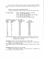
#l) EasyFormula:
WMs X Multiplying Factor(MF) = i06 setting
For 60:1gearratio(130):MF=2000
For 72:1 gearratio (5C, SCA, 132, 140, 170): MF -2400
For 90:1gearratio(220):NIF=3000
For 180:1gearratio(280,320,400):IVIF=6000
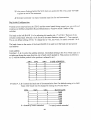
EXAMPLES, Assumean "F" value of 1000:
GEAR
RATIO
725
72
72
72
902
90
90
90
180
180
180
180
REQUIRED
RPM'S
26
33
62
18
25
30
2
7
10
15
MULTIPLYING
FACTOR
2440
2400
2400
2400
3000
3000
3000
3000
6000
6000
6000
6000
SET 106
PARAMETERTO:
12000
62400
79200
148000
6000
53999
75000
90000
12000
42000
60000
90000
EXACT Formula: Numberof encoderlines,timesthe encodermultiplier,dividedby the
encodercountsper second,dividedinto 60 : Motor RPM,. divided
by the gearratio : lableRPM
EXAMPLE #1, (For 5C, 132, 140, 170)Assumesan uF"valueof 1000
2000X2 :4000, dividedby 300,000= .01333,dividedinto60 : 4500RPM(motor
max),dividedby 72 : 62.5RPM tablespeed.
your minimumpositioningincrement(resolution)would be 4.00125
Note: With this example,
deg.
EXAMPLE #2 (220)Assumesan uF" value of 1000
2000X2 :4000, dividedby 300,000= .01333,dividedinto60 : 4500RPM(motor
max),dividedby 90 : 50.00RPM tablespeed.
an
uF' valueof 1000
EXAMPLE #3 (280, 320,400)Assumesan
2000X2:4000, dividedby 180,000: .0200,dividedinto 60 : 3000RPM(motor
m&x),dividedby 180 : 16.66RPM tablespeed.
Note: Thespeei of movement,and resolutionare verycloselytied together.Keep in mind, the
muimum amountof encodercounts,per second,the CPU can count b 300,000.Thefaster
the motor rotates,the more encodercounts it generates,per second Given this 300,000
maximum,the sloweryou rotate,thefiner the resolution.As you gofaster,you losea little
resolution. Your rotary unit b shippedwith the times2 multiplier. If you desirethe times4
'l"parametersettings,and a simpleiumperswitch.
multiplier,it is easitychangedA coupleof
Youcando it in thefield,but give us a call, and we will workyou through thefirst time,over
thephone.
Just as your new rotary,can movevery fast, it can alsomovevery, slow. Again it's a
matterof changingthe uF"valuein your program,andaltering"i06". The sameforrnuiaabove
still applies,just input smallernumbers.
First let me confirm to you, the minimum senings,for the "F" and "i06". (For more info
on thesepleaseseethe "F" command,and "i06oparameter)."F1" is the minimum setting,
which : .L% of the valuein "i06'. "i06" set at 1, would = one encodercount/per haif
lowestsettingwould be 250)
second.My recommended
EXAMPLE of above:2000X 4 = 8,000div. by 500 = 16 div. into 60 = 3.75 (motor
rpm) X by.01 ("F" settingtVoof iOO = 0.0375div. by 72(GearRatio) - 0.0005rpm
-28-
SFCTIOII 3: i PAR VTFTERSAl'r-n-,AIARiVI-CODE$
'in ParAmeters.
of the
are usedto tailor the operatingcharacteristics
The initialue, or setup parameters
controlto the systemin whrchit is beingused.The EAROM will saveany parameterchanges,
of powershutdown,providedthe"s"ave.is entered.Don't forget,you rnustbe in
regardless
switchset to manuai.
the programterminalmode,with the Manual/Remote
i00 SetFollowinlError.
Factorysening,-2500.This allowsa rnaximumdeflectionof .25obeforesendinga "Pos
Follow" error alarm.{Changingthismaycauseyour unit to not properlyfunction.The factory
for 99.7%of all usersneeds)
seftingis appropriate
i01 Setin PositionBand.
accuracyandis presetto our
Factorysetting,2. This is reflectiveto the motor/encoder
values
will
seriouslydamagethe encoder
Do Not Changellncorrect
moror specifications.
and/orcouuoller,voidingyour warranty.
i02 Setl{ome Direction.
directionin whichhomewill takeplace."0" is negative,
Onedigit,u0"or u1".Specifies
and" l' is positivedirection.
i03 Set Home Offset,
FactorySet:3000.Duringthe horningoperation,immediateiyafterthe encoder"C"
will causethe axisto makea moveby the specifiedamount
channelis detected,
this parameter
as the axis "zero"position.For homing
and direction.The final positionwill be interpreted
uM-Z
please
instnrctions.
and
instrrctiom,
see"G28"
i04 Set llome Feedrate.
the % of maximumfeedrate,of
Three digin, whereNNN is 0 to 999 and represents
ui06",the axis will be moving,duringthe homingoperation.An i04 valueof 500 wouldbe
50%,suchas a valueof 250 wouidbe 25%, of the maximumvalue,setin i06.
i05 SetBacklashCompensation.
thedirectionin which, andttrenumber
Five digis, basedon encoderlines,andspecifies
of encoderlinestheaxiswill overshootthedesiredposition,andreturn.Approachingposition
on positioning
looseness
alwaysfrom the samedirection,eliminatesthe effectsmechanical
accuracy.
positionandrerurn,whenthe axismotion
the axisto overshoot
A "+" numbercauses
u-n
u-"
whenthe axisis in the " + "
is in the direction.A
numberwill causetheaxisto overshoot,
direction.The signof the backlashnurnberindicatesthe direction,in which backlashtakeup
will occur.
by onedegree,.'henrerurn.
Ax i05 valueof 1600(72:l G.R.),wouldovershoot
-29-
i06 F eedrateSet.
: , 7 2 : 1& 9 0 : 1 )[ 9 0 , 0 0 0o n 1 8 0 : 1 ] w h i cehq u a i s
i s 1 0 0 , 0 0(06 0 1
T h em a : < i m u sne t t i n g
counts,
Thisis themaximurnamountof encoder
countsperhaifsecond.
100,000
[90,000]encoder
a fault This settingwill not takeeffect'
perhatfsecond,thattheCPUcancount,withoutcausrng
its own feedrate,arldis not
gntil the "Fnprogramfeedrateis read.The "T" cornmandgenerates
tablefor moreinformation,on this subject.
affectedby i06.Pleasereferto the feedrate
i07 SetServoI oop Gain Factor.
3 Digits,GainControl,i07NNN.
of the seryoloop in respcnding
WhereNNN is 1 to 255 andcontrolsthe responsiveness
to a positionerror. The largerthenumberthe "racier"the servoloop becomes.This parameter,
togetherwith the "Accel/Decel"factor:i08, canbe usedto criticallydampthe servoloop. It
response
until satisfactory
or decreased
thatthe gainbe graduailyincreased
is recommended
is obtained.
i07 is normally used to eliminateovershootsor slow position creep. Once i07 is
time.
theni08 canbe usedto setthe desiredacceleration
optimized,
Note #1zIt b importantthat the serro amp and motor/Ioadcombinationbe optimized
beforeattemptingto set i07.
Note #2: i07 may be u,ecutedin the ProgramBuffer by ustng107.
i08 Set { ccelll-tecelFactor.
RangeL to 32767with I beingthe shortestamountof time until indexerreachesfuil
ilmount.Averagevalue shouldbe: 800 to 1200.
beingthe greatest
speed,and,32767
'PosFollow " error.
Note: Lessthan 400 may makethe lock up or give a
iOo Jog FeedrateSet.
Similar function as i06 exceptcontrolsjog feedrateinsteadof program feed.The
setting1500to 15000.
maximumseftingmustneverexceedi06.Recommended
il0 Setmaximum positivetrav-ellimit.
will preventthe servofrom moving
7 digits.Measuredin encodercounts.This parameter
or instn:ctedto do so.If
beyondthe specifiedpositivedirectionlirnit, evenif it is colrlmanded,
thecontrolwitl ourputan errorsignalandstopmotion.Movesin the
the travellimit is exceeded,
oppositedirection,remainactive.
Seningi10 to 288,000wouldsetthe limit at the 180degreeposition(72:1). Default-1
(of0
'0'
Note: To use this feature i20 shouWbe setto
ill
Setmaximum negativetravel limil
7 digirs.Sameasabove,exceptcontrolstravelin thenegativedirection.Default-1 (oO
Cyclestart hutton in RemoteModg
i12 Enahlell\isahle
i12 setar 1 will enablethecyclestartin theremotemode,allowingthebraketo be used
from the front panel. Settingthis to 0 wiil disablethis fearure.
-30-
i13 Automaticpositiont'iasgeneratortime constanll.
From 0 to L27. Factoryser,90. Setsthe rareat which the servoloop examinesthe
it. 0
a biastern for compensating
sysrem'sposirionandfollowingerror drift andgenerates
=
=
I27 maximurncompensation
(oO, i
minimumcompensation,
il4 Yelocityfeedbackgain.
Factoryser,20. Range0 to 255.0 (offl. Conuolsthe amountof negativefeedback
in the ProgramBufferby using114.
Note: i14 nwy be executed
proponionalto velociry.
i15 Binarldata mode.
Factoryset,do not change.
il6 PulseGeqerator(handwheel)
is factorysetto "0", to enablethepulsetrain to changedesired'
1 digit. This parameter
aswell asacrualposition.For example,rotatingthepulsegenerator,1600encoderlines,would
disabled
causetherotaryto moveonedegree.ln this modethepulsegeneratoris automatically
movement.
by a prograrnmed
" i 1 6 " s e t t o " 1 " , c a u s e st h e g e n e r a t oirn p u t t o c h a n g ea c t u a lp o s i t i o no n l y , a n d
encoder,is rotated
doesnot disrurbthe desiredposition.For example,if the handwheel
1600linesand the tablepositionis zero, the controlwill move the motor 1600lines,
but rhe controller'spositionwill remain at zera. This function is mainly used for
l ode,
s e t t i n go f f s e t s .W h e nu i 1 6 "i s s e t t o u 2 "o r " 3 " , i t c r e a t e sa s p e c i a lh a n d w h e e m
where the handwheel(pulsegenerator)input is used to createa time base for the
control card. The result is that the handwheelcan now be usedto control the motor
rate, andwherethe movedistancescan be used
velocityas a functionof the generator
to changetheserates. This mode can be used to generatenonlinear lead screlv
patterns,or any other arbitrary motion patterns.Also, if a commonhandwheelinput
is used on any numberof controllers
, they will executetheir programsin precise
synchronization.
i17 Velocifyfeedforward gain.
Note: Shouldmatchil4.
ilE Automaticbias generatormodecontrol,
Factorysening,do not change.
ila Eulsegenerator(handwheel)scalefactor.
input.
5 digits,Factoryset.Controlsthemultiplicationfactorappliedto the hanCwheel
Note: The handwheelmodel# LPG-200will automaticallyadjustthe scalefactor.
i20 I inear/Circularpositionrange.
Factorysetfor unit gearratio.
Encoder
Gear Ratio
-240000
6 0 :I
-288000
72:I
-360000
9 0 :1
-720000
180:1
-31-
i21 Torguefimit control.
Factoryset,do not change.
i22 Nfl-tl modecontrol.
operatingmode,and "1'places the controlcard in a
One digit. "0" is for standard
directlyand
manualdatainput rnodewhereit is capabieof executingall buffer cornmands
does
and
not place
time,
at
any
uponreception.The tvIDI modecanbe invoked
rmmediarely
an "on-line"commandfeanrre.
any datainro the buffer. This is considered
To enterMDI mode,rype A}ltCRl; the controlis now readyto acceptany move. G
& M commandsare executedupon receptionof the [CR] command.Make certainthat the
feedrateis not zero,by rypingan F1000.This modecanbe usedby a hostcomputer,at any
time withoutusingthe buffer.
To exit MDI mode,usethe uS"stepor the "R" run co[rmand,or rype i220[CR]
This fiurctionis alsousedto "Nlow a remotestep via RS232terminal" seethis for
more details.
i23 Autornaticstepdelay & steptp hlock number.
First value(thedelayrange0-755 = 16msec.default- 0)
This is the pausetime berweenautomaticstepsin the Manual mode.
whichwill be autosteppedto. The block_number
The secondvalueis theblock_number
rangeis 0-65535,default= 0.
The fonnat is "23delay:block_number"
This is an excellentparameterfor recoveringto a particularblock number,after say
brakinga drill, or a machinecrash.It allowsyou to entera block numbersay,#49 and auto
stepto thatblock, withouthavingto cycleeverystepto get there.
The procedurewould be as follows: first W-Z retlrrn,then enter "in terminalmode"
O3L6:49tCRlThis wouldidentify"23 setthedelaytime,thenautostepto block#49 andstop.
lf 123is zerotherewill be no automaticsteppingof the program.
If A3 block numberis zero, the programwill auto-stepto the end of the program.
i23 is zeroedwhena "Q" quit commandis executed.
i24 Entry and display sg'le factor.
Factorysetfor gearratio to encodervalue.Seechartbelowto matchyour unit.
Gear Ratio i24 Value
60:1
2000:3
72:L
800:1
90:1
1000:1
180:1
2000:1
i25 Feedhold decelmodecontrol.
Factorysetting,1 do not change.
i26 Prompt modecontrol.
Factorysening,do not change.
-32-
i27 Crpinmultiplicationfactor.
Factoryseming,3 do not change.
i28 Work Zero setposition.
IIiII
DO NOT CHA}IGE THIS PNL$4ETER, SEE Pdfu{ffiETER LIST.
Unitsarein encoderlines,wirh a rangeof 7 digits.For example,a settingof 144,000
in ttrisparameter,would retainthe work zerosetpositionat 90 degreesfrom zera.
=
8.000encodercounts/perrev. X 72 (gearratio) : 576.00(ldiv. hy 4
The work zeropositionis savedafterpowershutdown in the EAROM.
i2q Brake-offdelay,hefqrestep.
Range:0 -255,LSB :16 msec.,defaultis 16 = 256msec.
0 definesa systemwith no brake.
The servointegratorgain will neverbe zeroed,if i29 = 0
tractory'\et: Do not change!
i30 Rrake on and remote step finish delay
Range: Q - 255.LSB = 16 msec.,default= 8 = 128msec.
This .i,'variableallowsthedelayof turningon thebrake,andremotestepfinishsignals.In order
thedelayof thestepfinishsignals,i29mustbe a non
for theui30"timeto be usedin determining
zerovalue(at least1).
i31 Stepcompletedelay.
Range- 0 - 255,LSB : 16msec.,default: L6:256 msec'
of the remotestepcompletesignalfor the "732"
Allows the pulselengthadjustrnent
rypesI & 3.
i32 Steptype. and polarity.
The formatis '\32 rYPe:Polariry"
Type: 0 - No SrepFinish. To seea visualrepresentationof i32 types,refer to page 7
of this manual.
with a delaysetby "i31'
1 - No handshake
by rernotestepinput,goinglow.
2 - Handshake
by secondremotestepinput,goinghigh.The remotestepshouldstayset
3 Handshake
until it seesthe remoresrepfinish changestate,or remainsetfor at leastthe time setin "O9"
with motionstart andresets the stepfinish when the
4 - StepFinish is synchronous
RemoteCYCLE START resets.
Note: B2 is a motionprogram buffer command.It can beput into a motionprogram to
changethe step Finish T)pe signal during the program.
The type, must be the samefor the stepfinish #L & stepfinish #2.
-33-
Pqlarity Chart
Value
0
I
2
J
StepFinish
StepFinish
J+''
NL
#r
0
0
1
I
0
Note:
1 = Closeto opento close.
0 = Opento closeto oPen.
i
0
t
I
I
be set
The polarifY can be indePendentfor step finish #1 and step finish #2. One can
to u1"and the other to "0o.
Allow a rqrnetestep-viaan RS232terminal.
A. Proceedas fcllows,for usingyour moves'
ui22"= L (021tCR])
I . Go to MDI mode
2. Typerhenexrmovevaluewith M18 @45MtS) to disablethe stepfinish#1 signal3. Type thenexrmovevaluewirh Mlg G90 M19) to re€nablethe stepfinish#1 signal.
4. Turn off MDI mode"i22" = 0 (Q}0tCRl)
B. proceedas follows for usingthe currentcontrolcardsbuffer moves:
1. To go into MDI, rurn off stepfinish#1, andstepby ryping':oZI M18 S"[CR]
2. TyprnguS"will stepthroughremainingmoveswithoutstepfinish #1 signai.
3. To re-enablestepfinish #1 rypeQzl M19 S tCRl
M18 andM19 commandswere added.
The block numberwill be incorrectbecause,
DiagnosticAnalysis.
problems,or just
to troubleshoot
This controllerhasa numberof failurealarms,designed
inform, if you enteredan invalid input character.The front paneldispiay,will indicate a
numericalor letterrype,of alarmcode,as well as a brief "worded"descriPtion.
-3+
Alarm Code
Failure Description
A*XISLIMIT
Motor or Cable defective or
disconttected.
8032 CPU
PRG BUF RAM
EAROM
CMD FORMAT
Internal RAM or CPU Failure
EXTERI'{AL RANI fault
EAROM failure
(a) Invalid commandor more
than 80 charactersinput.
(b) No < CR > after M30.
(c) Tried to (S)avewhile in
Remote.
POS FOLLOW
PROG LIMIT
RS232)WIT
PositionFollowingError
Motion limit failure
Tran^smission
cabre
error (check
type & seeverify lines2 & 3.)
EAROM XFER
U MO\aE
BRAKE CLAMP
EAROM saveor load failure
trl.Irtmoye failure
Brake clamp did not release.
(Checkif airlines are crimped &/or
solenoidwires.)
-35-
TrouhleShootingthe SUftX & UDNC
Com.Inunication Problems:
A) My computer doesnot comE[unicatewith the UDNC.
t) Confirm what rype of cable you are *irg, Standardor Null, and that communicationcabies
are pluggedinto properports.On most computersthe 9 pin pofi is configuredas COM 1.
If this b tr.ueon your computer. use a standard9 pin to 25 pin cable and connectto the 25
pin RS232cport on the UDI.IC.Note:.lf you have a o pin to 9 nin Null Modem cableconnect
to the a pin RS232cport on the LIDNC.
If this is not true on Jour computer. identify which port it is (ie: COM 2.) When you first
accessthe YuasaTerminal it will ask you to confirm your Port Settings,choosethe
appropriateport and confirm your changes.
If the 9 pin b COM I and it is being used by a mouse.use fie 25 pin RS232c port on your
computer, confrrm its port numbers and speciff this pott when you ftrst accessthe Yuasa
Terrninal. If the 25 pin is also in use,you must terminateone of the devicesoccupying a port.
2) Confirm that you are in DOS and not in Windows 3.1,95, orNT. The YuasaTerminalwill
not work properly in a multi-tasking environment.Do not ute a Windows DOS prompt! You
must be completely exited into DOS and have no other applicationsrunning.
3) My computer communicateswith m]' CNC but not to the UDNC. Your CNC may require
lines 2 and3 of the cableto be crossed{Null Modern.} Use a Standardcableor anacha Null
Modem adapterto the end of the cable.
4) I don't understandhow to usethe YuasaTerminal ConfigureMenu.
a) Confirm COM 1 or COM 2. (see#1)
b) Confirm BAUD rate. The default is 9600. This is an industry standardfor most 286 and
beftercomputers.If you are unsrueof what baudrateto use,leaveit at 9600.
c) 8 bit or 7 bit. Our defaultis 8 bit. If you needto usea 7 bit rate,you wiil also needto
configurethe dip switchesinsidethe UDNC. {See Dip Switch Configure.}
-36.
If
or benerprocessors.
d) Millisecondtirneout: 35 (Cefault)will work with 3861486x20Mhrz
5Oms.
50ms
time
to
out
you areusinga 286 or slowerthan20Mhrz 386i486,increasethe
or
lower.
higher
your
slightly
be
lrue
time
out
may
point,
good
is a
starring
e) Confirm the seftingare correctand enter"Y" to save.Your next screenwiil list the cards
addressed{A0 - A7 } and confirmationof corrrnunication{Yes or NO.} If everythingis
.
correctA0 shouldsav \TS.
5) I've tried eygr.ythingand still no communications.Unplug the power cord and removethe
cover from the IJDNC. Checkthe ribbon cablescoming from the RS232cports.They should
both connectto a 3" x 3" circuit board.On the back of the boardthey will connectto the
inner greencircuit boardof the 2larye boardsin the centerof the controller.Confirm that
they are securelyin their perspectivesocket.If theseare fine and you stiii cannot
communicatewith the UDNC, call the YuasaServiceDept at 800-421-9763for assistance
with the LTDNC.
B) My CNC Machine doesnot communicatewith UDNC.
1) Conlirm what type of cableyou are using,StandardorNuli, and that communicationcables
are plugged into proper ports. Your CNC may requirelines 2 and 3 of the cable to be crossed
{Null Modem.} Use aNull Modem adapterto the end of the cable.Somemachinesmay have
a Null modemport, in which casea Null Modem cablewiil be convertedto a Standardcable.
2) Confirm whetheryou are transminingat 4800 or 9600 baud rate.The UDNC has a default
settingof 9600.If you need4800 baudrate,seeDip Switch Configure.
3) Confirm that your CNC has the ability to sendand receiveASCII (American StandardCode
'B"'or Okuma's "User Task II." It is
of InformationInterchange)suchas Fanuc's"Macro
imperativethat your CNC has this capability oryou cannotcommunicatewith the UDNC.
4) Confirm that the CNC protocolsare properly configuredand that you have usedCarriage
Refurns<CR>. {Refer to your CNC manuai for more iCormation.}
5) I've tried evelrythingand still no communications.Unplug the powercord and rernovethe
coverfrom the UDNC. Checkthe ribbon cablescoming from the RS232cports.They should
both connectto a 3" x 3" circuit board.On the back of the boardthey will connectto the
inner greencircuit boardof the 2 largeboardsin the centerof the controller.Confirm that
they are secureiyin their perspectivesocket.If theseare fine and you still cannot
-9763and ask for
with the UDNC, call the YuasaServiceDept at 800-.121
comrnunicate
with the UDNC.
technicalassistance
-31-
C) My HCT doesnot communicatewith the LTDNC.
l) Confirm that the TiC {Terminal InterfaceCable)is securelypluggedinto both the HCT and
the IIDNC . Take carethat you did not bend anL of the 4 pins on the HCT.
2) Confirm that the baneriesare not low and/ordying.
3) Confirm that the preferencesare correctiy set on the HCT. Turn on the HCT, confirrn "NO
HOST" and pressthe EI'ITER bar. Scroll down the menu using the DOWN ARROW key
until you highlight "Preferences,"push "F" key. { F: OK.} The next screenwill haveyour
choicesin the black Boxes on the bottom of the screen.Each box correspondswith the button
below it; A - F. Select(defaultsetting)9600/ 8 biV Everr/A0. {Using the NXT key changes
the screenand options in the Boxes.) Push "El.lTER" to completethe selectionsequenceand
returnto the main menu.Highlight "OFF"- "ENTER"- "ON" to seeif you have established
communications.
Unplug the power cord and removethe
4) I've tried evgr.vthingand still no comr.ngnications.
IJDNC.
coming
from the RS232c ports. They should
the
cables
ribbon
Check
cover from the
both connectto a 3" x 3" circuit board. On the back of the boardthey wiil connectto the
inner greencircuit board of the 2large boardsin the centerof the controller. Confirm that
they are secureiyin their perspectivesocket.If theseare fine and you still cannot
communicatewith the UDNC, call the YuasaServiceDept at 800-421-9763and ask for
with the IJDNC.
technicalassistance
Error Code Definitions:
A-XIS LIMIT: Motor is restrictedor has failed.
Causes:1) Am phenol cableis not properlyconnectedto IIDNC. Make suremotor cableis
properlysnugged.
2) Stressto internalwires, {ie: brokenmotor cable,coolantseepage,}have causedlines
"R." "S." or "V" to breakor short.Performa continuiryteston theselines.
3) Possiblebad amplifier.Unplug the UDNC. Removethe Am phenolcablefrom the
UDNC. Take (3) 4" solid core copperwires and strip ll4" of insuiationoff each
end.Twist (1) end of all (3) wires togetherand electricaltapeor cap.Insert(1) wire
into the "R" socketof the UDNC Am phenolplug.Placethe (2) remainingwires in
"S" and "V" respectively.Apply power to UDNC and turn unit on; watch the
display read out. If the A-,YISLIMIT remainsrloHr ampltfier is bad. If the fuXIS
LIMIT is gone,you may havea damagedmotor. Call the YuasaServ'iceDept at
800421-9763.
-38-
EAROM: EAROMhasfaiied.Cail YuasaServiceDeptfor repair.
FollowingError.Unit is binding.
POSFOLLOW: Position
optimumstatedin the
i06 is settoo high.Do not exceedtherecorrlmended
1) Parameter
Causes:
i06 or lower
SUDX Manual.If workpieceis off centeror oveniyheavy,decrease
feedrate.
into the brakecylinder.Disconnectair
2) Unfiiteredair lines haveallowedcondensation
lines and power to the indexer.Removethe back plate,thnrst & brake platesfrom
the unit and examinefor rust and or corrosionin the chamber.If any corrosionis
found, removeusing a wire wheel or light grit sandpaperuntii ail tracesare
unit zurdaftacha
removed.{Be carefulnot to scareor damagecharnber.}Reassemble
to
SUDX.
reconnecting
airline
before
to
the
Fiiter/Regulatorllubricator
3) On smallerunits (5C, 130, 132-5C)the micro collar maybeoff set and restricting
rotation. Loosenvernier ring and test unit.
4) Tool crashhas createdunknown damageto unit. ContactYuasa ServiceDept.
5) Check the oil level thru the sight glasson your unit. If oil is low, add until sight giass
reads%full. On 5cl1301I32-5c,removethe uppergreasefiaing and add someoil to
the unit and replacefining.
BRAI(E CLAMP: Brake solenoiddid not releaseand or brake is binding.
into the brakecylinder.Disconnectair
Causes:l) Unfilteredair lines haveallowedcondensation
lines and power to the indexer.Removethe back plate,thnrst & brake platesfrom
the unit and examinefor rust and or corrosionin the chamber.If any colrosion is
found, removeusing a wire wheel or light grit sandpaperuntil all tracesare
removed. {Be careful not to scareor damagechamber.} Reassembleunit and attacha
Filter/Regulatorllubricatorto the airline beforereconnectingto SUDX.
2) Exhaustline has a kink in it and will not allow the air to pass.Remove the triangular
platethat holds the air finings from the SUDX. Examinethe lines for constriction.If
constricted,use electricaitapeto reinforcetube or trim if tube length is excessive.
switch on the UDNC off
3) Air solenoidis maifunctioning.Pushthe Remote/]vlanual
trigger
is heard.solenoidis
no
triggering.
If
and
listen
fore
to
the
zurdon
solenoid
bad. ContactYuasaServiceDept.
CMD FORMAT: Unrecognizedcorrunandstatement.
Cause:1) Does the programdownloadedhavea M30 {end of program} statementat the end.
2) Commandline is longerthan 80 characters.
-39-
3) Is rhe cursorflashingbehindthe M30 when you accessthe file. If so, push "ENTER"
to placean end of iine statement.
i) Misrypedcommandwas input. Examineinput line for and inaccuracies.
Dip SrvitchConfiguration:
Wirh the cover removed from the UDNC and the control panel facing toward you, you will see2
windows on the Btue (Amplifier) Board. Behind these2 windows reside2 banks of dip
srvitches.
The bank on the left (BAIr{K 1) is for adjustingbit nansfer rate, {7 or 8 bit.} There are 8 dip
switcheson this bank. Switches1 & 8 are set in the sarnedirection where as 2 7 ate opposed.
This is our defaultsetringof 8 bit. To changethis to 7 bit, set switch 5 to match switchesI & 8.
The bank closestto the centerof the board (BA]rfK 2) is usedto set the baud rate and specify
card address.
Card Address:
Switches l, 2, & 3 control the addressselection.Oru defauit setting is for A0 in which caseall 3
switchesare facing the samedirection,top of eachswitch pushedin. This position is referedto
as 0, with the bottom pushedin the position is referredto as l.
SWl
SW2- 000A0
100A1
010A2
110A3
001A-4
l0lAs
011A6
1_
I
SW3
I
CARD ADDRESS
A7
line.Our defaultseningis for 9600
4,5, & 6 controlthebaudrateof thetransmission
Switches
baud,otherbaudsmay be changedby settingthe switchesbelow.
sYv4
sws
sw6
0109600
1101800
0012400
1011200
011600
1
I
_1
:
extended.
0 bottomof switch
-40-
BAUDRATE
300
I = top of swilch extended.
Section5: RS232lllerface
A d v a n t a g e sf o r d i r e c t o p e r a t i o n .o p p o s e dt o M - C o d e u s e
l. You must oniy write a single CNC machineprogram, including the rotary movements; no
need to have a separateprogramfor the SUDX controller.
2. In viewing the CNC machinesCRT; you alwaysknow the positionof the rotary table,
relativeto any otherprogramline.
3. When programmingthe SUDX in absolute(G90), the SUDX will alwaysbe in the correct
Iocation, even when re-starting the machine program at another line, ( see "explanationof
movescommands",below, (G91) for more detailedinformation.
1. If you utiiize aCAIWCAD programfor developingCNC machinefiles, you may usethis
format for incorporatingthe S{IDX moves.
5. Macro programmrngpermitsthe useof "variabl€s" , which are very usefi:i for creating
"calls" for various qvpesof functions,such as half indexes,math functions,etc.
6. Sub-Programs may also be used,for easeof programmingrepeatmoves
Thefollowing information b only to be used as a guide. Cl{C machine controls may need
different machine parametersand pin configurationsfor the R5232cable,for each type and
make of controL Pleaseconfirm all information with your particular machine porameters
guide.
The reguirementsfor the FANUC control is as follows:
1. You MUST HAYE MACRO-B.
2. An RS232 cable,(pin configuration,and gendermay vary)
3. A spare,accessibleM-Code.
The following is the procedurefor interfacingan SUDX ProgrammableRotar,vtable, for
direct operation,through the Fanuc controls,via an RS232connection.
Getting the SUDX Controller-ready.
1. Removethe controllercover,and changedip switch#1, bit 5 to open.This will changethe
dataformat to 7 bit, evenparity, one stop.Fanuccontrolscan only communicatein this
format. We normaliy ship the SUDX units with the 8 bit configuration,however,if you are
just purchasingyour unit, we would be huppyto changethis switch,prior to shipment.
2. The baudratesettingof the SUDX controlleris 9600bps.This can be changedby dip switch
with the
alterationsinsidethe controllerfrom 300 bps,to 19,200bps.If you corrlmunicate
-41-
FAI{UC conrrolwirh otherdevises,and are locked into a baud rateotherthan 9600 bps,
pleaserefer to page #.10 for specificdip switch changesfor the baud ratevou desire.If
9600 is OK, then no changeis neededat the SUDX controllerside.
Gefting the Fanuc Control rerdy.
Thefollowing is a seriesof steps,in order to prepare the FAI'{L|C control, to communicate
witlr the SUDX controller. Be advisedthat some of the psrameter settings may change,
depending on the particular controL The settingsbelow, arefor the FAI'{UC OM. Confirm
parameter settingsfor your individual controL
1. Depressthe "DiagnosParam"button.
2. Pushthe " PageDown" keY once.
3. Turn the function switch to "MDi" mode.
4. Change"PWE" to equal"1" , then "fhlPUT".
5. Depressthe "DiagnosParam"button.
I'VO''
=
6. "PageUp" Onceto the
Page,usecursorto makesureI/O 0.
7. "PageDown"to changeparameters.
Changethe followingparameters.
0002 Bit #2 = 0 (setsdataformat)
rl
, ,
Bit#0=0
0057 Bit fl4 = 1 (givescarriagereturn,line feed)
(setsto 9600bps)
0552 :11
8. "Pageup" to "PWE"=1 (setting#2)
9. "[N|PLIT"''0,' "PWE"=0
10.Depress"PROG"button,and"RESET"
FANUC 20 & 21M CONTROL
Note: Pleaseuse the following parametersettingsonly as a guide.Checkyou actual
machine parameter listing for confimation.
Param#
0000
0020
0100
0101
0102
0103
6001
Setting
0 0 0 0 11 0
Chanel0
r 0000000
10000000
Description
ASCII Code
VO Channel
LF/CR
StopBit
A
11
00010000
9600bps
CR/LFafter"DPRNT"
-12-
to OPENDIP
Sinceall FANUCcontrolsonly work with 7 DATA BITS,it wiil be nessessarv
This will setthe SUDX controllerto 7 DATA
SWITCH# I PIN #5 in theSUDX controiier.
BITS,EVENPARITY;1 STOPBIT.
You are now readyto write a TEST programon theFAI{UC control.
PROGRAM
program#
POPEN;
i B 9 o M 3 0] ;
D P R N TI A 0 E F 10 0 0 G 9
PCLOS;
M2l ( exampleof CNC machineM-Code)
M30;
%
90 degrees.
Onceyou executethis programtherotarytableshouldmoveincrementally
what is happening
Essentially
hereis thatthe RS232porton theFANUC controlis being
openedfor communication
"POPEN", thenthe contol is beingtold to sendthe characters
insidethesquarebrackets[ ] out throughtheport "DPRNT", in ASCII format.Oncethe SUDX
executea move.
controllerreceives
thisdata theCNC machineM-Codewiil automatically
RS232 Interface to FANUC Controls
Addendum
The foliowing is a methodof placingthe Macro "DPRNT" commandline, in a variable.This
allows the programmerto use a simple program line to executeany SUDX rotary movement.
CNC llachine lllacro Program (sample)
%
:9010
POPEN;
DPRNTIAOEF1000Ge0B#2[33] M3 0l ;
PCLOS;
M21; (exampleof MachineM-Code)
M99;
%
-E x n l a n a t i o n
Programsbeginningwith a "9" are consideredMacro programnumbers.Someof these
programsare caliedwith G-Codesand othersarecalledwith M-Codes,(pleaserefer to your
-.13-
controlmanual).In the DPRNT line note the "B#2", this requeststhe programto look @ the B
"index movement"in the main machineprogramiine. The [33] statesthat the index degreeswiil
and to look 3 digits left of the decimal.If
be 3 digits (maximum),for example"180" degrees,
then you may wish to input 17317
needto usefractionaidegreeslike "180.5025degrees,
,v-ou
total digits, with 3 digits left of the decimal.Also note the "M21" afterthe "PCLOS". This is a
sarnpleof the M-Code neededto executethe DPRNT colrlmandline. This M-Code will change
dependingon the brand of CNC machine.This N{-Codewili be the spareM-Code accessed
via the REMOTE cable.
Additional ParameterSeffings.
#220 = 15 (forGi5)
# l0 Bit 4 = 1 (MacroProtect)
Main CIYC Program Line Example
G15 8180
(This line in the main programwould providean absolutemove of i80 degrees)
onlythe "G90"to "G9i", In this
Note:You may wishto write anotherMacroprogramchanging
= 16.Theprogram# wouldbe
#221
caseyou wouldusea Gl6 insteadof a Gl5 , andparameter
9011.
SpecialNote: This is only an example,the parameter seffingsand codesmay be different
for evera control. Pleaserefer to your program manual.
FADAL control is as follows:
1 .You MUST Have Macro Capability, CNC 88HS (1992)or new controls.
2 . An RS232 cable,(pin configuration,and genderdescribedbelow)
Getting the SUDX Controller ready.
I . Removethe controllercover,and changedip switch # I , bit 5 to open.This will changethe
data format to 7 bit, even pariry, one stop. Fadal controiscan only communicatein this
format. We normally ship the SUDX units with the 8 bit configuration,however,if you are
just purchasingyour unit, we wouid be huppyto changethis switch,prior to shipment.
2. The baud rate settingof the SUDX controlleris 9600 bps.This can be changedby dip switch
alterationsinsidethe controllerfrom 300 bps,to 19,200bps.If you communicatewith the
Fadalcontrol with otherdevises,and are lockeCinto a baudrateother than 9600 bps,give us
a call, I 800 421 97 63, and we wiil let you know the specificdip switch changesfor the
baud rateyou desire.If 9600 is OK, then no changeis neededat the SUDX controllerside.
Getting the Fadal Control ready.
Thefollowing b a seriesof steps,in order to prepctrethe FA,DAL control, to communicate
with the StiDX controller. Be advbed that some of the parameter settings may change,
dependingon the particular control. Confirm parameter settingsfor your individual control.
Using the baud rateparameter,setthe Fadalcontrolto communicateat 96008PS.Using an
RS232cable,connectthe Fadalcontrolto the SUDX controller,using the DB25 senal
connectoron both. For the pin configr-uation,
seebelow.
You are now ready to write a TEST program on the FADAL control.
PROGRAM
program #
#WAIT
''
#SPRINT'' AOEFlOOOG9lB9OM3O
M20 (exampleof machineM Code)
Once you executethis progmm the rotary table should move incrementally90 degrees.
Essentiailywhat is happeninghereis that the RS232port on the FADAL control is being
openedfor communication , then the control is being told to sendthe charactersinsidethe
doublequotes" " out throughthe port "#SPRNT" , in ASCII format.Once the SUDX controller
receivesthis dat4 the CNC machineM-Code wiil automaticallyexecutea move. Then the
RS232 port on the FADAL is closed and the controi will automaticallycontinueto the next
Iine.
ExBlanationfor FADAL Addendum
The anachedsheetsexplain a new methodof commandingthe SUDX to move to a desired
positionvia an RS232cablebefweenthe SUDX controllerand the FADAL control.Using the
FADAL MACRO function (#SPRINT)we arenow abieto eliminate the need for the (I\{20,
from the FADAL) for positionconfirmation.The REMOTE cableis not evenconnected
benryeen
the FADAL and the SUDX controller.Commandedposition and the verification of
positionis all accomplished
via the RS232cable.
The theoryfor this is as follows. (Pleasereferto N5 of the MACRO program)First the ASCII
data is output from the FADAL control to the SUDX controllercommandingthe rotary table to
move to position.Oncethe move is complete(referto N7 of the V{ACRO prograrn)a "Y" (send
currentposition)is sentin ASCII to the SUDX controller.Position(i.e. 90.000, for 90 degrees)
is sentfrom the SUDX controllerto the FADAL control.Oncethe FADAL seesthis data,(to a
variable,refer to N13 and 14 of the MACRO program)the VMC proceedsto the next block in
the main machineprogram.If the positiondatasentis not correct(i.e. 85.000,for 85 degrees,
{5-
when rhe actuaipositionshouidbe 90 degrees)then the FADAL will go to ER-ROR(seeN 15 of
the MACRO program).
rnain
This entire sequenceis all placedinto a MACRO program,which is "CALLED" in the
program.(seeN3 of the TEST program).The acrualdata fiat the customerwould need to input
These
into the FADAT main prograrnis quite simple,(seeN4 & Nl l of the TEST program).
program
simple cornmanCsare all that is neededto index the rotary table. Another MACRO
could be wrinen for incrementalmoves,if desired.MACRO program# 09998 is set for absolute
(G90) movements,as this is strongly recommendedshould the user needto re-starthis machine
program in the middle of the program.ABSOLUTE enablesthis featureas the rotary table wiil
aiways move to actual desiredposition, regardlessof it's previous move.
This MACRO and TEST program is now includedon ail program disks sentout with each
SLIDX unit. The FADAL user need only load theseprogramsinto the FADAL control (seepage
#1 of the ADDENDUIv{) and they are ready to go.
prior to shipment of the SLrDX we can (if requested)set the communicationPROTOCOL
correctly (7 d,atabit,even pariry, one stop) and the customerrequestedbaud rate (we normally
ship at 9600 BPS).
MORI SEIKI TV.3O & 40
Parameters
# 7201 100 (G CODE Numbers)
# 7202 1 (G65P)
#7203 (any Sub Program#)
Sub Program List
00001
# 100-#4003
POPEN
Il
B#2[33]M30A
DPRNTIAI A0EF1000G#[20]
PCLOS
M21
I'v199
Pleasecheckyouractualmachine
Note#l: The aboveis only meantasa guideor reference.
andMacroprogramfor verification.
parameters
Note#2: The "A1" at thebeginningandendof theprogramline maynot be neededon vour
UDNC 100controller.
-46-
pleaseseethe generalMon TV-30 and'10
parameters,
Note#3:For setup and communication
setuD Daqe.
OKIIw-IA control is as follorvs:
1. You MUST HA\rE "USER TASK II"
2. An RS232cable,(pin configtuation,and genderdescribedbeiow)
3. A spare,accessibleNf-Code,if you requirea stepfinish signal.
Getting the IIIDX Controller ready.
1. The baud rate seftingof the SIIDX controller is 9600 bps. This can be changedby dip switch
alterationsinsidethe controllerfrom 300 bps,to 19,200bps.If you communicatewith the
Okuma control with other devises,and are locked into a baud rate other than 9600 bps, give
us a call, I 800 421 9763, and we will let you knowthe specific dip switch changesfor the
baudrate you desire.If 9600 is OK, then no changeis neededat the SUDX controilerside.
Getting the Okuma Control ready.
Thefollowing b a series of steps,in order to prepare the Okuma control, to communicate
with the SUDX controller. Be advisedthat sotne of the parameter settings may change,
dependingon the particular control. The settingsbelow, arefor the Okuma OSP 7000,5020
and 5000. Conftrm parameter settingsfor your individual control.
Changethe following parameters.
Optional ParameterWord.
#39 = 9600
Optional ParameterBit.
#i 0i010011
#12 00111011
You are now ready to write a TEST program on the Okuma control.
'
'AOEF
1OOOG91
PUT
'B
PUT I8OM3O'
PUT $OAOD
WRiTE O
-47-
v{181
M2
Once you executerhis programthe rotarv tabie shouldmove incrementally180 degrees(with
the M 18 I output)Essentiallywhat is happeninghereis that the RS232port on the Okuma
control is being openedfor communication"PUT" , then the controi is beingtold to sendthe
charactersinsidethe quotes,out tluough the port, in ASCII format. Oncethe SUDX controller
receivesthis data the M181 commandwiil automaticallyexecuteamove. Then the RS232porr
on the Okuma is closed,the conftol will automaticallycontinue to the next line.
Yasnac I 80 & IID(-3 Control, via. RS232 Port.
r80
l. Go to the maintenancescreen,depresssoft key "AI LPAIL{" , then softkey#5, seiectRS232.
2. Next a set up screenwiil appear,input dataas foliows:
3. Make surethat the pin configurationfor the RS323 cable betweenthe UDNC controller and
the I 80 control, are correct.Pleaserefer to our config. diagram for the UDNC pin-out, and
the machinediagrarn..Most likely you will need a "NIJLL MODEM" adapter,switching
pins #2 and#3. In addition, note that the DB-25 connectoron the IIDNC-100 is female,and
the DB-25 on the CNC machineis usually fernale.You wiil needmale endsfor both sidesof
your RS232cable.
4. To test a progftrm, go to MDI mode on the Yasnacand input the following :
s3 100=(A0EF1000G90890M30)
M21 (exampleof machineM-Code)
This wiil initiate a movementof 90 degrees.
Note: Make sure that the "Manual/Remote" switch is on Rernote.
rf
Make sure that you input "A (the number zero) E and not the letter O,
If it doesnot work at this point, re-checkyour RS232connecfion,this is most likely
where the problem is.
MX.3
The set up for this control is very similar to the I-80. The command( #3100) and programdata
is the sarnealso. The following is a step procedurefor communicationprotocol.
1. Depressthe " PRM" switch.
2. Pushthe soft key " RS232"
This should bring you to the settingpage:
3. Depress" PROG" then go to either "MDI" mode or urritea programto test.
Again, checkpin confrgurationof the RS232cable,and makesureyou are connectedto the
correctport on the CNC machine.
-{&
The reguireFentsfor the Yasnaccontrol is as follows:
l. You NIUST TLAVEVIACRO-B, this shouldbe a standardcontrol feature,but checkto
be sure.
2. An RS232cable,(pin con{iguration,and genderdescribedbelorv)
i. A spare,accessibleM-Code,if you requirea StepFinishsignal.
Gefting the YasnacControl ready.
Thefotlowing b a seriesof steps,in order to prepare the Yasnaccontrol, to communicate
with the SUDX controller. Be advked that some of the parameter settings may change,
depending on the particular control. The settings below, arefor the Yasnac 180& tlIX-3.
Confirm parameter settingsfor your individual control.
l. Go to maintenancescreen,depressthe soft key"ALLPARA", then softkey#5, selectRS232C
2. Next, a set up screenwill appear,input the dataas follows:
You are now ready to write a TEST program on the Yasnac control.
PROGRAM
program#
#3100: (A0EF1000c9i 890M30)
Mzl (exampleof MachineM-Code)
M30;
o
Units
BPS
StopBit
Bits
Parity
Xon/Off
Rts/Ctl
PariryISO
RS232
ChannelNo.
ISOiEiA
ControlCode
S t o pB i t
Baud
Pariry
TN
RS232C
9600
1
8
off
On
OUT
RS232C
9600
I
8
off
ofr
On
On
off
On
Output
I or 2
ISO
ON
1
9600
OFF
-49-
tooi for the
programming
YUASA TERIvINAL V 1.X is an all-purpose
program
L,DNC-100Controiier.It allowsfor on-lineterminaloperations,
wrinen
the "C"
in
is
It
theI-IDNC-100.
eCting,upioadinganddownloading
programminglanguage.
SYSTFM REQ(IIRENMIYTS
or
YUASA TERMINALVersion1.X runson anIBM PC,PC/AT,80286,
cornpatibleswith at least 640K and one disk drive. In addition,one
standardserialport is required.
COPYT|{G TITE SL?PI TED DISKETTE
Making a backupcopy of your disketteis essentialfor insuringthat the
programsare not destroyedif the original disketteis ever erasedor
darnaged.
If you havetwo floppy disk drives,you may backupthe originalYUASA
disketteasfollows:
1. Insertyour DOS disketteinto Drive A anda blankdiskeneinto Drive B
andresetthe computer.
2. At the A> promptrypeFORMAT B: andpress<ENTER>.
fype:COPYA:*.* B: andpress
3. Afterthediskin DriveB is formatted,
<ENTER>.
4. RemovetheDOS diskette.PlacetheYUASA diskenein DriveA and
press<ENTER>to the prompt.
5. After the originaldisk is copied,storeit in a safeplaceandusethe
backupcopyasyour workingmaster.
If you have a hard disk drive, you may back up the original YUASA
diskeneasfollows:
1. At the C> promptrype: MD YUASA andpress<ENTER>.
2. Type: CD \auASA andpress<ENTER>.
3. InsertthesuppliedYUASA diskin thecorrectdrive& Type: INSTALL
thenpress<ENTER>.
IYote:ThesupplieddisketteoperatesunderDOS Version5.0 or greater
NSTALLNG KIASA TERMNAL ON YOIIR C: drive
To installYUASA TERMNAL to your harddisk,insertthe backupcopy
of the provideddisk, go to the appropriatefloppy drive, then rype
NSTALL andpress<ENTER>.
RI-IIYNINGYUASA TERVTII\IAL
To run YUASA TER-MINALfrom your harddisk,f,vpeCD YUASA and
press<ENTER>.
Thentype: YUASA andpress<ENTER>.
-50-
After the rwo windows appearon the screenand a listing of the fi.rnction
keys appearsin the right-handwindow, you will be prompted w'ith a
questionsuchas the foilowrng:
SystemConfigtuedas:
Card Number: 0
Port: COMl
9600
Baudrate:
ASCII Type: 8 bit, no pariry
35
Cornmunicationtimeout(miiliseconds):
Do you want to changeit? (y/n)
Note: All UDNC-100 controllers are factory set to the above settings
unlessotherwbe requestedbeforeshipping.
If yoru ConuollerCard is configuredforthis setting,simply press<N> or
<ENTER>. If you press(Y), you will be allowedto configureYUASA
TERMNAL to the proper card address(0-7), port fype (com 1 or com 2),
(19200,9600,4800,
2100,1200,600,300),ASCII type (8 bit no
baudrate
pariry, 7 bit even pariry), and timeout setting which is proper for your
controller sefup.Also, refer to the Alt-Fl (Configure) key descriptionin
Section2 of this manual for detailedinstnrctions.
YUASA TERMINAL proceedsto poll the availablecards(A0 through A7)
and determineswhich cardsare connectedto your system. You will then
be placed into Terminal Mode. If no cards are connected,or the
communicationport in your computeris not properiy configured,you wiil
get a message:'No Cards found'.
Pressingthe "EscapeKey" allows you to exit YUASA TERMNAL and
refurn to DOS. If you wish to try to specify the interfaceconfiguration
again,use the ALT <F1> Key. YUASA TERMINAL will enter its normal
terminal mode regardlessof whether any Controiler cards are connectedto
the computer.
2.0 njASA TERMTNTAL MODE
After YUASA TERMINAL successfuilydeterminesthat one or more cards
are connected,you may proceedto communicatewith the cards. The lefthand window will act as a direct terminal to the card. Anything you qvpe
will be sent to the card (once you press<ENTER>, and anything sent from
the card wili be promptly displayedon the screen.
EXAMPLE: Typing the lefter uJ"and pressing<ENTER> will causethe
rnotor attachedto the cardto jog in the positivedirection. Type another"J"
or "Q" to stop the motion. Typing the lowercaseletter"p" or "Y" will
causethe ControllerCardto sendits position datawhich will be displayed
on the next line of the screen.
Note: Upon entering terminal modefor thefrst ttme, YUASA TERMI^\AL
automatically addressescard A0. Thus the position data displayed by the
'? " o, '7" commandwill be theposition of card A0. To changethe card
being addressed,type 'A"and the card's number(0-9) or letter (a-fl and
press <ENTER>.
-51-
describedin the YUASA SUDX Manuai,
In additionro the on-line corrrmands
the follo*ing function keys aPPIY:
< FI > - EDIT r-VARIABILE
This function key retrievesup to 32 "i"-parametersof the card currently
addressed.The parametersare divided into fwo screens.To display the
next screen,pressthe <Pg Dn> key locatedon the numenc keypad.To
ciisplaythe previousscreen,pressthe <Pg Up key locatedon the numeric
keypad. Oncethe parameteryou wish to modify is displayedon the curent
screen,you may accessit by positioningthe cursorbar over the parameter.
To move the cursor bar, use the Up Arrow and Down A:row keys, and to
rnodify the parameter,press<ENTER>.
After positioning the bar over the desired parameter and pressing
<ENTER>, rhe following messagewill appearin the right-hand window:
CHANGE - i:<x
Mocimum: xrc(xxx
Minimum: )OCCCC(
Default: )OOCCC(
unia:
)ooccc(
Now:
)OCCCC(
ENTERNEWVALUE:
:)
The values listed refer to the appropriatevalues of the parameteryou
selected.You may entera new value,or press<ESC> to cancelthe change.
If you enter a value which exceedsthe critical valuesof the parameter,a
warning messagewill flash and you will be promptedto try again.
When you finish revie*ing the i-parameters,press <Esc> to rerurn to
Terminal Mode, or "s" to save the parameters.
< F2 > . DTSPLAY I/O STAT
This key displays the current VO starus.
< F3 > . DISPLAY CARD STAT
This firnction key displaysthe currentcard status.
< F4 > . LIST PROG BTIF
This key will display the buffer of the card currently addressed.You are
prompted for the starting line number, after which each carriagererurn
keysuokewill display a pagefuil of consecutiveprogramlines. The axis
datawili be displayedin userunits setby the "i24" variable. To rerun back
to TerminalMode, press<ESC>.
-52-
< F5 > - MnT MODF ON/OFF
Thrs function key allows you to enterthe lvlanualData Input lvlode. In thrs
mode motion commandswill be executedas they are entered. "lvfDl On"
will be dispiayedin the lower right window when MDI is active.
< F6 > - OPEN LOOP MODE
This mode allows the userto test the motor and encoderin an open ioop
mode.The arow keys aliow the userto adjust the motor output in 0.1 and
0.01 volt increments.By changingthis output,the usercan drive the motor
and determineif the encoderpositionfeedbackdirectionis correctbefore
closingthe servoloop. The <ESC> key wiil exit this mode and gradually
return the output to zero.
Warning: Do not erceed 4.00 volts, as it may damagethe Rotary Table
and/or the Controller's Amp Board Resulting in a costlynon-warranty repair.
< F7 > - POS/T'OLLOyy/TIMF'
This fr.rnctionkey displaysthe position, following error and time for the
card connectedto your system.
<FA> . DOS COMMAI{NS
This key exits you to DOS allowing you to perforrn DOS commands.
Typing <exiP will rerurnyou to the YUASA program.
< FlO> . FILE EDI1OR
This key aliows you to create,edit, download,and uploadprograms. See
section3.0 beiow for detailedinstmctions.
The following functions are activated by holding down the <AlP key and
pressingthe appropriatefi.urctionkey. The alternatefunction key seiectionscan
be viewedon the right-handscreenby holding down the <Alp key and pressing
<Q>.
AIt < Fl > . COMM SET L?
This fi:nction key allows you to re-configureand re-poll you system. You
may changethe communicationparameters(port,baudrate,etc.)and re-poll
the availabiecards.
Note: Thisfunction is automatically invoked when YUASA TERMINAL
is first run. The current interface configuration is shown, and you are
askedrf yo, wish to changeiL If you answer'Y'or'!', loH will be asked
which of the following interfac€sysu wish to configure:
CardNumber:(0-8)
This is usedto addressconrollers that havebeen"Daisy ChainedTogether"
via a seriaicable.
Note 1: Factory defaultfor a single controller is 0.
Note 2: The (0-8) choice is a programming tfpo, it should be (0-7).
<2> COM2
P o r t :< i > C O M I
whereselectionsI and 2 referto the standardRS-232ports on your PC.
-53-
When you selectthe RS-232interface,you wiil selectthe baudrateof 9600
from a menu of choices.The rateyou choosernustmatch the seningon the
DIP switch on the Controllerscard(s),and, in general,the longerthe cable
is, the lower the baudrateshould be.
Note 3: Factory default is 960Abaud, callfor information if you need to
change.
<1> 7 bit evenparirv
ASCII Type:<0> 8 bit no pariry
l{ote 1zFactorydefaultis I bit no parity, callfor informationrf you need
to change.
(MIMMUM 20)
Timeout(msec):EnterCommunication
bit for
This puts a limit on the time the programwaits for a handshake
readingor writing.
AIt <F2>-NISKON/OFF
This key wiil togglethe DISK ON option. With DISK ON, mostdata
receivedfrom the cardwiil be echoedto the defaultdisk drive underthe
filename'TERMDATA.MCC.' This frle rnaybe examinedby loadingit
throughthe file editor. WhenYUASA TERMNAL is first run, if the fiie
TERMDATA.MCC already exists, it will be erased. However,all
usesof DISK ON wiil appendall incomingdatato the file.
subsequent
Whenin the POSIFOLLOV/iTIMEmode,the datadisplayedwill alsobe
sentto disk. To view thisfile, you mustrurnoff DISK ON. Thiswiil close
the file so you canview it with the file editor.
AIt < F3 > - PRTI\I"TON/OFT'
This key will togglethe PRINTERON option. With PRINTERON, ail
datareceivedfrom the cardwill be echoedto any standardline printeras
well asto the screen.Makesurethatthe line printerhaspaperandis OnLine.
AIt <F4>. DISPLAY OFF
This key stopsdatafrom beingdisplayedon the terminalscreen.This
allowsyou to senddatato the printeror disk at a fasterrate.
AIt <F5> - SAV PRGR&J.VAR
This key will savethe currentProgramBuffer andi-Variablescurrentlyin
the RAM to the EPROM.
AIt < F6 >. PRINT SCREEN
Wiil print the currentscreento your printer.
AIt < ElO >. IIELP FTLE
<l> - LoadHelpFile : Allowstheuserto viewa HelpFile(*.HLP).
1> - ReformatHeip File:Reforrnats
theHeipFile for easierviewing.
<ESC>- E)OT:EXIT theHelpMenu.
3.0 YTIASAEDTTOR
The editor is a word processor
for Controllerprogramsof up to 65000
characters.
In thissectionof theprograrn,
linesrypedin theleft windoware
-54-
nor senrto rhe Controller,but insteadenteredinto the editorbuffer. The line
numbercorrespondingto the line of the editor buffer to which the cursor is
currenrly pointing is displayedin the right window. lvlovementof the
cursoris possiblewith the four Arrow Keys. The following editing keys
alsoapply:
PgUp - Displaysthe previouspage(23 lines) of the currentprogram.
PgDn - Displaysthe next page(23 lines)of the currentprogram.
Displaysthe first page(23 lines) of the currentprogram.
Home End - Displays the last page (23 lines) of the curent program.
Alt-l - Insertsa blank line at the currentcursorposition. All subsequent
linesare moved down.
Alt-D - DeletestJreline at the currentcrusorposition. All subsequentlines
are movedup.
Nt-C - Clearsthe currentbuffer and filenalne.
- Togglesbetweenthe "NSERT ON" and "NSERT OFF" modesof
Ins
the editor. lnsert Off allows you to type over previously enteredtext, while
LnsertOffwill move any previously enteredtext to the right of the cursor.
Note: Each line is limited tofifty-two characters and the editor is limited
to 65000 characters. The editor will signal you when the last line is
reached
In addition,the following function keys may be used:
< Fl > - IIPI OAD I-VARIABLES
This key uploads the current I-Variables into the displayed buffer fiie
shown at the bottom of the screen.
< F2 > . FILE UTILITIES
This key allows you to load, save,insert,or deletea program on the current
disk. In addition, you may print the file currently in the editor or a file
savedon a diskene. You will be presentedwith the following selection
menu in the left window:
<4> - DeleteFile
<l> - Load File
<5> - Print CurrentFile
<> - SaveFile
<6> - Print Disk Fiie
<3> - InsertFile
<9> - DOS Commands <ESC> - EXIT
Enterthe nunber of your selectionat the prompt. The selectionsperform
the follo*ing tasks:
<1> - Load File: Allows you to bring a fiie in from disk to the editor
buffer. Any program currently in the editor buffer will be erased.
1> - SaveFile : Allows you to savethe programcurrentlyin the editor
buffer to disk.
Note: Filenames are limited to eight standard characters and unless you
spectfyyour own extension, the extension ",MCC " is automatically added to
anyfilename. Disk and subdirectoryspecifierscan be enteredin front of a
-)f,-
filenam€, up to a total of 40 characters. The default filename for a newly
createdprogram in the editor buffer is iVOllAttE.MCC.
<> - Insert File : Allows you to bring a file in from disk and insert it into
the prograrnclurently in the editor buffer at the presentcursor location.
<4> - DeleteFile : Allows you to deletea disk fiie.
<5> - Print CurrentFiie : Allows you to print the fiie curently in the editor
buffer to the standardprinter for the s,vstem.
<6> - Print Disk Fiie : Nlows you to print a fiie on disk to the standardfiie
for the system.
<9> - DOS Commands: Allows you to perform DOS commands
< F3 > _ DWNLD&SAVF',, F',.rrF'
This key dowrloads the cu:rent buffer file to the controller and then saves
the datato its internal EAROM.
< F4 > . LIPLOAD PROG BIJF
This firnction key uploads the program buffer frorn any card and appends
it to the program currently in the editor's buffer.
< F5 > - DOWI|I OAD Fn F'
This key downloadsthe currentbuffer file to the IJDNC controiler. Before
downloading you will be asked if you want the program buffer cieared
before download. This is necessaryif yotu file has motion program data
and no "2" or "E", clearthe buffer, corrrmand.After the downloadyou will
be refurnedto Terminal Mode.
Note: The editor's buffer is not erased;you moy accessit again by pressing <FI0>. If
there are Bny errors, hining ony kq will return you to the /ile edit buffer.
-56-
t'i" ParametersrMaintenanc€,Service&
TableDimensions
SUDX-280/320/-100
J0/170 suDX-2?!
132/l
SUDX-5CTA) s_uDX72:l GearRatio 72:l GearRatio 90:1GearRatio 180:IGearRatio
-2-<0
-250
i00
i00
i00 -250
i00 -250
i01 2
2
iOl
i01 2
i01 2
:
0
i02
0
i02
0
i02
i02 0
0
30 0 0
i
0
3
0
0
0
3
i
0
3
3
0
0
0
i03
i03 3000
3000
250
i04
250
i04
250
i04
i0.+ 250
250
1600
i
0
5
1
6
0
0
i
0
5
1600
i05
1600
i05
r 600
80000
r 00000 i06
1 0 0 0 0 0 i06
r 00000 i 0 6
1 0 0 0 0 0 i06
i07
60
45
i07
ia7 45
35
i07
30
1200
i08
1000
i
0
8
8
0
0
i
0
8
8
0
0
i08
800
i09
1500
r5 0 0
i09
1500
i09
i 500
i09
Ls00
l
1
1
l
-l
i
1
0
i
l
O
iio
i10
1
i
-1
-l
ill
-l
ill
ill
ill
i12 0
it2
0
it2
0
itz 0
0
il3
90
i13 90
90
il3
90
il3
90
i14 ?0
20
il4
20
ii4
i14 2A
20
0
il5
i
1
5
0
0
i
r
5
0
i15
0
i16 0
i16 0
i16 0
i16 0
0
20
ir7
20
i17
i17 20
i17 20
20
i18
12
i18 12
i18
12
12
i18
12
1024
i
1
9
ii9
1021
1021
i19
1024
i19
1024
-720000
-288000 i20 -360000 i20
-240000 i20 -288000 i20
0
iz|
i21 0
0
i21
:2t0
0
t22
0
0
122
t22
0
0
i22
0
i23
0:0
i23 0:0
i23 0:0
0:0
i23
0:0
i21
I
I
2000:
1000:
i24
I
i24
800:
i21 800:1
2000:3
I
i25
i
i25
1
I
i25
i25
l
0
t26
0
i26
0
i26
i26 0
0
i27
3
i27
3
i27 3
t27 3
3
FactorySet i28 FactorySet i28 FactorySet i28 FactorySet i28 FactorySet
i29
32
i29
32
i29
0
32
i29
32
i30 16
i30 16
16
i30 16
i30
16
i
3l
16
i
3
l
1
6
i
3
1
1
6
1
6
i
3
1
16
i32 2:0
t32 2:0
i32 2:0
i32 2:0
2:0
SUDX.I3|]
60:l GearRatio
-250
i00
'n
!
rul
i02
i03
iO;l
i05
i06
i07
i08
i09
i10
it I
il2
ir3
il4
i15
i16
it7
il8
i 19
i20
Lzl
122
i23
i24
i25
i26
t27
128
i29
i30
i31
132
-\
Note: On i29, i3I, & i32,you may needto change these values depending upotl J,our Finislt
signal requirements.
Maintenance,Servicer
and Table Dimensions
suDx-sCr5CA,132-5C
INDEX
0ESCRtPTt0tt
P A GE
I I II R O D U C
I OI I { . S P E C
I A L C A UITO } t S
SPEC
I F I C A TI O I I S I I I D E XH E A DDI H ' H SI O X
PARTS 8 REAKDOIII{
P A R T SL I S T
PREPARAII OHS
I,IA
I I { T E I { A } I C&EA D J U S T I { E I t T
l {o .
4
4
I l O T O Rl l J R
I II{G DIAGRAI{
I NTRODUCT
I ON
T h a n k y o u v c r y n u c h f o r c h o o s i n g o u r T p D Xp r o g r a a r a b l c I n d o x c r . l h i r I n d c r o r h a s
b c c n n c r l l y d a s i g n a d a n d r r a n u f u c t u r c dg r e c i s i o n i n d e r c r n o t o n l y f o r t i r e a n d
co!t saving purposabut also bcing drsignad considaring naintcnanca. lafaty tnd
d ur a b i I i t y .
Houever.you ar. rcqucstcd to fully undcrstandits ooeration rcthod ano
0 a c c s s a r yr a i n t o n r n c . t o g c t r c o u i r c d a c c u r a c ya n d a v o i d a c c i d a n t s ,
t 0 e h o g c y o u c n j o y i t s c r c c I l c n t f c a t u r c s a n d a 9 9I i c a t i o n s .
SPEC
I AL
CAUT
I ONS
T o o g c r a t c t h i s u n i t b y f o l l o u i n g p r o c o d u r c sd e s c r i b c d i n f o l l o u l i n g D a g c s ,
hou,ty€r. you ara rcqucstcdto pay spccial attcntion to follouings.
O
Tir. to tiac, chcck thc rotor cablcs for any daaagc.and if any daragc is
found, repair it uith tapc. ctc irrcdiatcly, and call your dcalcr to gct a
ncrl cab I c to rca I eca.
Coolant cntcring into insidc of tho notor fin uill caur. cncodcr failurc or
uirc dllagas. Thcrcforc. chcck thc bolts, nuts of thc rotor cablc oonncctor
and th. notor fin pcriodically.
llcvcr ulc thic unit rlith loosc bolts and nutt.
A
Avoid havine tools or uorkoiccor crash into thc indcxar.
NEGLECTING
ABOVE
CAU:rroNS
IIILL
i,OID
OUR
wARRAt{ffY
POLICY-
SPEC
I F I CAT
I ONS
I I { D E XH E A D
inch ( rr )
S PI N D L EO .D .
3.86 (98)
S PI I I D L EB O R E I . D .
1.l4 (29)
C E I { T EH
REI G H I
4 . 3 3 ( 11 0 )
PLAC
I i l 0 DT R E Ct T
0t{
G UI D E B L O C Kt I I' D T H
IIOR
I Z O X T A /L V E R T
ICAL
0 .6 3 ( 1 6 )
S PI I I D L EI I O S E
I{AX.IIORI(LOAD HORI ZOIITAL
Ibr (kg)
VERTI CAL
T O T A LG E A RR E D U CI O
T } I R A TI O
I IIDEXI I{G ACCURACY
tnith in
REPEATABILITY
utith in
10"
BAC[LASH
u ri t h i n
t 60"
SPI XDLE RUHOUT
l l , EI G H T l b r ( k e )
0.0004 T. l. R.
D I MENS
2-3/16-r0ull
11 (20)
22 (l 0)
Lz72
t30o
6 0 .6 ( 2 7 . 5 )
I ON
o.6 7
-1-
PARTS
BREAKDOU'N
'-'4\
__/
Dc{
\*a
\c/
{\vf"rffito
€.o e6 *r#
$'*w"
e\rp
*w
b-o
{%
2-
L
PARTS
PARf ilo.
IST
6 I Zt
t
PARI tAltl
-t
D I G R I TI f i I 8 L
SP:NDL8
1
H E I . 6 0 C K E TS C R E T
1
L
3
S P : I I D LB
4
B0LT
8 6r . S 0 C R 8 T
5
?ARI {A}tB
IARI l{o.
Itlx6
I
srzt
t
36
PACTIN6
1
3'l
S N A L LS C R B I
.t
38
STALPLAIB
I
tt5 X E
e
Itsx t1
3g
SI^L PLAII PACKI.NC
H 6 I . S 0C K E I S C R3 l f
1
f
n6x6
.fO
H E I .S O C K T TE O L T
2
I
P A R A L L E LK 8 Y
I
6x6xl0
41
I I E T A LT H R O S TP L A i I
].
7
IORil THEEL
1
4Z
H 8t . S 0C t r E TB 0 t r
2
8
V.RING
1
v-85A
43
T H R U S6TC R T I (' B )
1
N B t D t E8 8 r R i ! l c
z
FHIA4566
44
t i { R u s Is c R B t (aA )
1
I
RIN6
RACETAY
3
Fl RA{565
46
SINGLTBALI ETARIIIO
2
62EZL
48
G U I D ET A S H S R
4
FTRB.IO24
47
lIEIDtS EBARIHG
2
TilIA. I O2{
4g
r 0 R i Sl l A F t
J.
50
r0R{r||8tAL
1
51
COUPLIIIG
I
NA-I3
52
H t t , s 0 c [ B T s c RE l l
4
It{x6
c0 0{074
10
'l
't
1
I T A I I JB O D Y
t2
I N R U S T PL AI t
13
v -RitlG
I
1
.|
u-70A
T6X18
f!l
x l2
T H R U S II I U T S O L O I R
I
15
',tAcHIr{I SCREL
1
r3x S
16
HtI. S0CKtT 6CRBlf
I
i6x6
S T O P P T RP i I I S P R I I I G
1
53
O -RIN6
1
t7
1a
PIII
STOPPER
L
54
E E A LC O L O R
1
t.9
T H R U SiIl U T
1
55
n t I . s 0 c x E Ts c R t f
2li{x{
zo
clutcH
| 1
58
i0?0R ILA!lGl PACIIrl6
zt
ROLLEG
T U]OE
I 1
s?
i0r0R tLlllcs
1
22
R o r L E RG U I 0 [ - G U I D t
| 1
58
[ B r .s 0 c l l t B 0 L T
41;5x15
23
C L O S I , R6SP I [ D t 8
COLLET
z 4
E rilDLt
| ccrrsr cLosuRR
2 S
I ROLLBR
za
I
l1
x E2 t 3 t ?
59
JOILSIAL
J.
6 4
| roton
1.
2
6 s
lspniucllAsHER
4
n5
l x r N D r sB o L t ( l )
1
6 6 I n g r s. o c r l TB o L r
4
15x15
2 1
| tlorcrton
1
6 1
| coolrrc rIN PACIINC
I
2 A
I C t t r s B ) l I PPL t
2 | 1/|-2E UllF
6 A
I l o r o n c o o l l f { 6I I N
1
3 I116xt
6 I
I coHxsctoR
1
RBC-20I
3 I t66l
?o
'1 2
l[sr.soc[81loLt
2
ll6 x
r { t r .s 0 c t t T 8 0 t T
4
i3xl3
73
c 0 0 L I t l Gl l t l c 0 v 8 R
1
74
C O U 6 RP A C T I N G
i
29
3O
H T I .B O L T
I6IALIASRER
a
a
3l
curDl 8Loct
2
32
H 5t . S 0 C t E l B 0 L T
z
33
H A X D L 8T 0 1 1 ( 3 )
1
3,[
H tr . s 0 c I t T 6 c R E r
z
35
6Cntr c0vlR
SPIXDLE
1
n 6x t 0
;5 x 10
-3-
t0
PREPARAT
1 ) U X P A CI IKI G
I ONS
l l l h e ny o u r c c c i v c t h a u n i t ,
ckack el I of f o I lorrlings arc
includcd.
I OABLE
I i l D E X H E A D[ ' I T H } I O T O R
a)
b ) O P E R AITO I { I { A I I U A L
2)
I H S P E CITO I I S H E E T
lt|ipe off tha rust proof oil
3)
off, )
l(cver usc th inner (0r. the 9a int tli | | conc
or burrs and clean thc table
ckack the nachinc tablc surfacc for cracks
c)
urhcrs you ara lounting
rrrith lieht
oil'
thc unit'
the guidc block to the hsad
uhen using thc hcad in vertical position. sct
and insert it to the nachine tabla T-SLoT.
using clanp bolts'
E ) Sct the haad to thc nachino tablc securety
4)
T
ADJUSTMEN
&
NTENANCE
shiPncnt, houcvcr'
Thc unit has becn ful ly inspectcdand adjustcd bcforc
rsd after long usc.
f o I l o u i n g n ai n t c n a n c e a n d a d j u s t n e n t a r t r o q ui
GEARBACKLASH
1 ) |JJORT{
t h c f a c t o r Y , h o r l c v cr ' Y o u a r s
T h e b a c kI a s h h a s b e e n a dj u s t e d r li t h i n t l ' , a t
r s Q u G s t c dt o a d j u s t i t a f t e r l o n g u 3 8 '
MAI
a ) H o u rt o a d j u s t t h e l l J o r nG c a r B a c k l a s h '
, r c r o v . ct h e
f in covcr @
1 . R a n o v c4 ' B oI t s 6 D r u hi c h a r c f i x i n g c o oI i n g
'
cooling fin
"or",'--@
)
Fin @
Thcn pull thc cablas (loosely l3yinB in the l{otor Cooling
vcry carcful lY.
l ' l o t o r c o oI i n g F i n @ ,
z . A f t c r r c r o v i n g z B or t s @ u r hi c h a r e f i x i n g t h o
- 60nn (2" - 2'1" )
pull back the llotor cooling Fin by 50
and looscn (slightlv) thc 4 Bolts
3. Turn up thc cooring f in packing @
'
t" the llain Bodv @
f i x i n g t h c l fo t o r F l a n s c @
@
bolt @
, and tXrun slightly truoHex'sockct
4, Rcrovor""; 0r"," @
'
r r r ihc h f a s t o n r e t a I t h r u s t p l a t c @
Hex
r o c a t a do n t h c b a s a b o t t o n a n d v o u u r i l l s o o
5 . R c n o v cz H e x B o r t s @
i n si d e '
s o c k o t s a t 3 cr c u , @
To dccrcasethe Backlash, aftcr looscning
s e t S c r e u rs l i g h t l v a n d
s c r e u Jb y t h e s a i l s a n o u nt '
t i g ht o n B
T o i n c r e a s e t h c B a c k l a s h . l o o s o nB
3 cr c u ' .
s cr c u ,a n d t i g h t s n A
A f t c r t i g h t e ni n s b o t h s c r s u , s( l & B )
A
-4-
sf ight ly and adjusting tha backlash, tighten the golts
and
@
t i g h t c n u p A . B s c r o u , su i t h 3 a r o f o r c e . T h c n t i g h t e n u p t h e H c x .B ol t s
r ,i t h s c a I l t l a s hre
and r€aesenb
l e s e aI p l a t e
.
@
@
@
6. Tighten tho 4 Bolts
@
@,
fixing the |fotor Flanso
@
7. lnsert the Hotor Coolis Fin
@
Eoltr@to
fir the fin.
Chack if
into the l,lotor
@
ths l,lotor Fin Packing @,r
thc Motor Cooling Fin
.
@
to the main body
and t ighten thc z
betueen thc l,lotor Flangs
@
and
0thcr'risc' coolant lay go into the inside of l{otor Fin and uiill causc
daragc to thc cncodcr.
."Ull Lltj.".:*{.reJ*."s.3*lI"tr"-y"!.l.".u.eia...t"qrral.3"y"."
8. Inscrt thc cablcs (had becnpullcd out in 1.) carcfully into tha
clearance of thc ilotor Cooling Fin
and nake rurc the cable
@
conncctor part locatc at tha cooling fin
.
"ou., @
9, Attach thc Covcr packins
and fix thc Cootins
@ _t. thc l{otor fin @
Fin Covcr
uritilI Bottr
@
@ .
Also. bc carcfull to do this sincc coolant tay cntcr insidc of thc
l{oto r.
llotcs : Aftcr coaplct ion of adjustncnt. lcasurc thc backlash again. Thc grcatcst carc
nugt bc takon about thc fact that stcpping rotor ray be out of control and tha
i n s t r u c t c d a n g l . c a n n o t b a c x c c u t c du , h c nt h c b a c k t a g hi s t o o l i t t l a .
l f t h c b a c k l a s h i s o u t s i d c t h c t o l o r a n c cu r h i l c t h c u o r n a n d t h c l r h e c l f i r l l y
cngagoduith cach othcr, rakc adjustncnt bv rcforrina to stco b) Hourto adjust
t h a b a c k l a s ho f t h e u o r n 3 h ! f t i n t h a t h r u s t d i r e c t i o n .
b ) H o r ut o a d j u s t t h c b a c k l a s ho f t h e u r o r rs h a ft i n t h e t h r u s t d i r c c t i o n
1 . R c n o v es c a l p l a t e
@
and netal thrust platc
@
2. RcnovcHox.sockct scrsws
@
.
and Thrust sc rcu, B @
.
3 . B a c k l a s ho f t h c u , o r ns h a f t i n t h c t h r u s t d i r c c t i o n c a n b e c l i n i n a t c d b y
t i g h t c ni n g T h r u s t s c r c u A
p r o vi d c d n G x t t o T h r u s t s c r e u ,B
@
@ .
( g c s u r Gn o t t o t i c h t c n t o o i l u c h . )
-5-
4. Aftrr !djurt!.nt, !cr.u Thrurt lcrar B into $lc ao3ition ii touchcr to Thrurt
rcr.{, A tnd rrturn by one or onc rnd half rotation. and thcn out rr bolt hola
of
Thrust rcrrs I rnd tappcdholc of Thrugtscrcu A togcthcr. Aftcr that. tight.n
Hcx.rockct
and rcarsorblr l{ctal thru:t ltato
@ , scat etatc @.
""r.n @
2) orLilrG
I cnE^Strc
Lubricato thc unit aftcr clcaning thc grsrsc nipola.
a ) S q p p l v s o i n d l c o i l t o t h o u n i t t h r o u g ht h c g r c a s c n i p g l c l o c a t c d a t t h c . . o indicator uting an oi t gun.
b ) G r c a s ct h c u n i t t h r o u g ht h c g r c a s c n i p o l c ( l o c a t c d a t t h e b o t t o n o f t h c u n i t )
avcry 3 lon ths.
-6-
stIDX-130,r40, 170,220,280
N
D
E
X
DESCRIPTION
PAGE No.
I NTRODUCT
I ON
SPEC
I A L C A U IIO N S
S P E C I F I C A T I O N SI H D E XH E A DD I I , I E I I O
SN
PARTS BREAKDOI,!I{
P A R T SL I S T
PREPARAII ONS
O P E R A T I NI G
N S I R U CI O
T NS
t { At N T E N A t i &
CE
n O l U S i l txer
H 0 I 0 Rt ! t R l | i Gq l A c R A t(' st u o x - i 3 0 1, 4 0 . 1 7 0 , 2 2 0 )
H 0 T 0 Rt i IJRI N c D t A c R A t {( S U 0 XZ- B 0 )
INTRODUCT
8
8
I
13
L4
ION
T h a n ky o u v e r y m u c h f o r c h o o s i n g o u r S U D XP r o g r a n m a b l eI n d e x e r . T h i s I n d e x e r h a s
b e e n n e u l l y d e s i g n e d a n d m a n u f u c t u r e dp r e c i s r o n i n d e x e r n o t o n l y f o r t i m e a n d
c o s t s a v i n g p u r p o s e b u t a l s o b e i n g d e s i g n e dc o n s i d e r i n g m a i n t e n a n c e , s a f e t y a n d
durabilitv.
H o u e v e r , y o u a r e t ? e g u e s t e dt o f u I l y u n d e r s t a n d i t s o p e r a t i o n n e t h o d a n d
n e c e s s a r ym ai n t e n a n c e t o g e t r e q ui r e d a c c u r a c y a n d a v o i d a c c i d e n t s .
[ l J eh o p e y o u e n J o y i t s e x c e l l e n t f e a t u r e s a n d a p p l i c a t i o n s .
SPEC
I AL
CAUT
IONS
T o o p e r a t e t h i s u n i t b y f o l l o u i n g p r o c e d u r e sd e s c r i b e d i n f o l l o u l i n g p a g e s r
h o u r e v e r ,y o u a r e r e q u e s t e d t o p a y s p e c i a l a t t e n t i o n t o f o l l o u i n g s .
O
A l r r . r a y us s e F R L ( A i r f i l t e r , R e g u l a t o r , L u b l i c a t o r ) t o s u p p l y c l e a n a i r t o
t h e a i r c l a m p u ni t .
0 t h e r u l i s e , i t n l a y c a u s e m aI f u n c t i o n s o n t h e i n d e x e r , s u c h a s i n s uf f i c i e n t
p i s t o n r e t u r n , f a i l u r e s o f c l a m g / u n c l a m pc h e c k p r e s s u r e s u i t c h o r t h e
s o l e n o i d v a l v e f o r u n c l a m pg e t t i n e u l a t e r i n t o t h e i n s i d e o f t h e i n d e x e r .
@
T i m e t o t i m e , c h e c k t h e m o t o r c a b l e s f o r a n y d a m a g e .a n d i f a n y d a m a g e i s
found, repair it uith tape, €tc imnediately, and call your dealer to get a
n e u c a bI e t o r e p I a c e .
coolant entering into inside of the motor cover uill cause encoder fai lure
or uire danragesT
. h e r e fo r e , c h e c k t h e b o l t s . n u t s o f t h e m o t or c a b I e
connector and the motor cover periodically.
Never use this unit uith loose bolts and nuts.
O
A v oi d h a vi n g t o o I s o r u l or k p i e c e s c r a s h i n t o t h e i n d e x e r .
SPECIFIc'ATIONS
II{DEXHETD
IABLEO.D.
TABLE
BORE
CEHTER
If ISIT
PLACIHG
DI IECIION
GUIDEBLOCI(
ITIDIH
SPINDLE
BRAXE
tdn0G-Ks.-n
(Lbs/foot)rat 6Ko/ol(85PSI l
BRAKE
SYSIB.I
m ( incfi)
lh-
SUDX.130 stDX-140
SUDX-170 st.DX-220 srDx-280
110( 4.33', 110 ( 5 . 5 i ' 1 7 0( 6 . 6 y 2n ( 8.66' 280(11.0?
3 0( l . 1 r ) 25( 0.sr) 4 2 ( 1 . 6 5 ' ) 4 2 ( 1 . 6 5 ' ) 4 2 ( 1 . 6 5 ' )
Hmz.5
r{36P3.
0
lt36P3,0
1,136P3.0
t05 ( 4.13',) 115( 4 . 5 3 ' ) 1 3 0( 5 . 1 r 160 ( 6.3S 190( 7.4t
FNRITONTA]/ \trRTICn|
la (o.s51z
)
6(40)
18 (0.70966'
1 5( 1 1 0 )
e(65)
2s (180)
Pl{EttfAIlC: *7 Ka/e# (7c^1oopsTI
PARATLELISI{
OFIABLETO-re
4s (325)
0.02 (0.000s
LAELE A,\IAL COIICENTR
ICITY
0 . 0 1 5( 0 . 0 0 0 6 ' )
SQTJAREI{ESS
OFBOTIO,IIO
SIDEBASE
0.01 per 100 (0.0004'pe
!_ 4')
ITAX
UPRK I.ORIZOIIIAL
30(
66
50 ( 110) 80 ( 180) 120 260 180(
LOAD
VERIICAL
1 5 ( 33)
2 5 ( s s 40 ( 90) 60 i30
90 (
iIAX.IHRI,6I VERT
ICALLOAD
LOADAGAI400( 880) s00( 1100) 600 ( 1300) t000( 2200) t500 (
IISTIABLE }ilRIZONIALLOAD
SURFACE
250( s50) 300( 660) 400 \ 880) 600 ( 1300) 900(
CIRCITIFEREXT
IAL
8s ( 1s0) 1 1 0( 2 4 0 ) 1s0( 330) 200( 440) 300(
TAELE
ROTAI
IOttALTORqJE
(Lbs/foqt)*atlrpn
}tAX.I'ORK
INERIIA
Kg.cm.s2( lbs.in.s2)
LIERICAiION
TOTALGEARMIIO
(r,,rth in
I I{DEX
lilG ACC{iRACY
REPEAIABILIW (urt h i n
MCKLASH
(rut h i n )
Ilf IGHTUJAUBTAELE
DIMENSTON
2 . 3\ 1 6 )
3.s( 2s)
0.6 (0.s)
1.5(1.3)
?q
( 25)
3.5(3.0)
0 ll -MTl.{
r/60
t/72
+3ff
4.8( 35)
400)
200)
3300)
2000)
660)
27 ( 1e5)
s . 2 ( 8 . 0 ) 23 ( 20)
+ 22.s',
1/90
1/180
6'
l'
30 (
66)
38 (
84)
49 (
r08)
82
180) i28
282
PARTS
BREAKDOIT'N
(suDX-130)
' ''lr,(
- -",
ri) --'a-7t&:'(D,n
(/\."\',, ,' ','t
,()as]j'I.,9"t",&-trg\J
ctl"'AX,*H/
^)),
,rt""''r'{q'/'1
'i
),,
,ar
k
2', 1{, ;'g)l 7'W
* @\..fr
/a')
,&* (/dt
d,4G
J:\J', *SF%
q \-
oo-@G)-=-/-$
@,M'",9)
'?3'
\ '.'
?,
[3). \ fgF'', '\ i /^6-)"
\ i_-.
y
-------,,=/N
\ \
r--rr r?.,r
) r, eP
,*===_]e..==tAz\6/^
\\/
G\\
./
f$V/\
trJ
Y
nr-,
\ 64)@
13-/,-(o'J=(.M#5'7
td_[^,,whxp, @
(B-' )f-@',
b6a;*,%,(6WWq
*')-'
)\;",s:"rl\o-n
\- S-g
--o'
/ J\\c6\^q\
^,r{.1'(%-@,\:t'\
\.- \
,qhd1T)5$'^*\g
*'ru''*'
*_,",:fg/
*rh\_\a
/ { /s/*b*
rty\A/
r
)Gl
\!/
/6)
\?
\,\'
PARTS
BREAKDotT,N
(suDX-140,
170,
220)
?
( r,:,,*l
€l
'\\\,.
t71r.'b,p
..,g?
ffil{.p
tE,1.'4.3;,A,h:A-^
(e)
A (A''
/ n \
'V<n)
'=*ri
Gi'l'r^"r{s'
/
v \'M
O
€,'
\,
\-\/b'' i*( @r.,
/Pe:'\
rb,
tg
A^)N'td''-''(e'r ^(tfl / (g
\ Y' @ e'-L/
e-@ "' 1r
(
\\@?
o-o-t \,d
\)
\'-"
/=\
e,3,,
,9)-@
\
\
\
\/v
e.'*d
'*7'-/*-:/
,3l-'
("@
\;*
/
/
/,b
\b /,i
c-W',b
/
/
,,
\
*'@
\/
,/ f,-€)
-3-
/
r-.'
\91l-o
/
Vgre-rg
/
-@.
e-i-s\^
@
/\n \e\
\
-Q-l
\o
"/
/
@
/
\(
\\
\/
V
\--l
I
\-W
\
\\
@-o
o- /
(
\tr3
\lA
)6o
PARTS
BREAKDoTTIN
(suDX-2BO)
?,,N:,,{*,,8,
q,
5:! @*=g],
vw
"'Nb''tffie,$''
d'P:lis-x$
,
,or))g,A
*.,W$;*
i, \' -_'\:o'O, )'t
\-z\sv,
c-@\d*'r
'n
\$
/ !@ /
e. l
d
,b%,' p t*rt
(o
\
J- ,,,-@/
/!:#_
v \ t'g,/@7'
*ry
?!V.p
*&r'7{"&,
'=€'='^AA/^\\/
z-b
"* ,
\
e-o
e
K-
\
/-\
\
\d, \
\/
/
rg)-. \ ,6)l'',,/\,, /Y
--------r/)
\*
/^/^
v:-/J/ w
,A
(ro/
-(
/)q
\!9/
.
PARTS
PARI
No.
,/
L I ST
PAR
I HA}IE
X
0i I seal
tI
Q'
ty
I
i
7 I F r o n th o u s i n g
3 H e x s. o c k e t b oI t
4 U Hrng
5 T a p e r r o | | e r b e a rrn g
(
t'15x
12 (6)
H 6 x 1 8( 6 )
(6)
H8x20
I
s100
sl15
s140
1
I
HR3291
4J
HR32914J HR3
29I 7J
l,t4x6
H5x6
H 4 x i 8( 8 )
H 5 x l s( 6 ) r{6x
15 (6)
Ring dog
_6
I
I
H e x s. o c k e t s e t s c r e u ,
Sprndle
I
[tbrm rrlhee
| _--X
H e x s. o c k e t b oI t
T h r u s tn u t
1
I
1 u05465
I3
0 Rrng
1
I
Prston_
U Rrng
X
? 0 P r e s s u r eo l a t e
'tL
tsraked r sk
't't Hex.
socket boI t
23 0 Ring
24 B r a k e b o s s
25 H e x s. o c k e t b ol t
, r 26 0 i I s e a l
X
27 0 Ring
2B I h r u s t p I a t e
28-( Pi ; t o n r e t u r n s p ri n g
79 Seal uasher
3 0 Hex.socket boI t
31 B a lI b e a ri n g
x
40
{4r
42
43
44
45
46
G70
1
I G110
(8)
H6x18
--)
f t 8 x 1 8( 8 )
-)
H6X8
l{6x12
ItSx15
HR32913J H R 3 2 9 l 5 J HR32g20J 32928
AD60759
G80
AD709010 A 0 9 5 1 1 5 1 3
A 013016014
Gg5
G125
G170
G120
G145
G230
(8)
Ir{6r12
(12)
t'{6x14
sl20
I
I
\ , , H 5 x i 0( 6 )
1
I
s50
-+
f i 5 x 1 2( 6 )
s56
s67
s90
II
(6)
\.,, H4x12
T KE75S06
I
I
(
(
()
()
sr32
(3)
uJ6Sl(6)
(6)
H6x15
(
6000 1)
-)
H s x 1(26 )
H 6 x l s( 8 ) l.t8x18(8)
KE80956
KE90l107
s150
4 5 5 6 8 - 1 6 7 A3568-172AS568-275
-t
-+
-)
6001 (3)
t
I
KEl201357 K E 1 6 0 1 9 0 8
-, (4)
+ (8)
H 6 x 1 8( 8 )
-)
(4)
-)
-+
6002 (3)
1 R T 1 2 1 6 1L2R T5l 19 i 6
-t
-r (l 2)
( 12 )
6003 (3)
LRTLL7?224
'l
[tJo
rn shaf t
Parallelkey
0uter r ing
I h r u s t b e a ri n g
Z
G175
t
Spacer
rt7 0 R i n s
38
39
--)
t{5x10
I
0i I seal
t8
36
-)
i
(
Ig
32
33
34
35
HR32922J 3 2 9 2 8
I
-.r--
LL
4 5 5 6 8 - 1 6 8 AS568-27i
t
I
L2 R o ll e r
4
I 3 Hex.socket set screur 4 H5X6
i 4 I l a p e r r o | | e r b e a ri n g I H R 3 2 i9Jl
'|
Ib
tsody
"Ll
r{8x25 (8)
j
I
U
t0
It
S I Z E
SUDX-140 SUDX170
SUDX-220 SUDX-280
g
n
z
uE709212 UE7 A
u E8 5 1 1 0 1 3
uEl1014014 u E l 4 07l 0 1 4
SUDX13O
I
I
()
()
GSl226(2)
-)
5 1 1 0 1( 2 )
-+
I
I
s40
s45
I
L
AUA0
ilm1
-t
Aru02
I
I
ANOO
AilO1
-+
ANO2
AIUO3
AN03
s40
s45
s55
s60
V
U,fo
rm metaI
Lock uasher
Locknut
0Ring {
l{eta I th rust p I ate
Hex.socket boI t
0i I gauge
Hex.socket set screu,
fletal plate oacking
5x5x20
GS1528(2)G S 1 7 3 0 ( 2 )
(1)
GS1o24
(1)
51100
s48
s48
s t i 0 2( 2 ) s l 1 0 3( 2 )
s55
s60
't
.t
4 l.l5x15
I FE-I2
t
l.{5x12
-+
--t
-t
-t
l,l6x15
ft6x20
-+
t
I
-5-
H6xlg
J
-)
-)
-)
-t
-)
PART
No.
PART HAI{E
_1L
t - t exs. o c k e t b o l t
-
.tY
euio" bi;i
CU
nex . s o c Ke t b o I t
SeaI unsher
b1
ty
SUDX13O SUDX140
I
1
l.l5x12
-, l{5x8
!f'q rylel! ate
47
I
(.
-5
!9U9.1 b"I------
b3
Seal uasher
n e x .n e a d b o I t
I
Srbi;ba"
t
I
H e x s. o c k e t b oI t
6 1 igq_!"b l-.__gup_
ot _. u H r n s
bJ
(
I'J6S
I ( 1)
uJ6
tlJSS
1
H6X8
ujl0
H i 0 x1 5
(8)
I'tSx30
I
1 s67
I trJl0
X
tllave unsher
-)
H6XIO
1
bU
{
I7
E
SUDX170 SUDX-220 SUDX.28O
spacer
(3)
(6)
l,t6x35
-t
t U I H e xs. o c k e tb o l t
II
Iolo_rj lanse_
72 H e x s. o c k e t U oI t
13 lSolenoidairvalve
;;i-;;----,-l;--_-i-/.r
lnex:_socHoott
(
/ b I q u r c k j o r n t ( s t r a i s h t ) l(
tt
Pressure su,rr
tch
-;I
9 Rins
84 | Spur sear (H)
85 | Paralel key
U b DU- S er v o m o t or
dt
bp r I ng urasher
UU
Hex.socket boI t
Hotor cover
Hex.socket boI t
UU
g0
X
I
H 8 x 3 s( 6 )
-)
-)
M 1 0 x 4 0( 6 )
-l
_-I
0Rine
0r I cap packing
sli0
-t
ujl5
-+
(rrrs)
ccz35
-)
-)
-+
1RT172213
l,l5x1g
-t
-+
t{6x25
-21
-DC24VSR
100EI
l.l4xI
(
2
)
TL6-01
(1)
(1)
rs6-01
(2)
-)
I 76120200
-)
-)
-)
-)
s70
G40
--t
EM2
E643
J
-)
-+
-+
+
-+
4 l,l5
4 H5X15
X I
-)
l,{5x18
ltSx25
+
-t
-+
-+
-)
-)
-t
-+
G50
-)
1
L
6 l{5x18
Union
UC
Nipple
vb V" lrt" - th-b;x nut
97_ U ni o n
YU
Huffler
99 l{otor cable
102 I n d i c a t o r
IU3
Hex.socket boI t
lu4
L
I
93
94
-t
-)
s85
1
I
l
t
nex . s oc k e t b o I t
uJi2
-+
-+
I
91
vt
l.l8xl0
-)
H12x20
l,l5x25
I'l
/b I Qurcll_/ggl!91!')
-)
-)
-t
I
I i
-t
-)
I
I
H6X1O
-'
(3)
uJ8
| I
2
2
bg I tUashe
r
*
-)
-)
-)
I I
uu_fsour sear (UJ)
7g
-+
-)
-)
-)
-)
UI2
b4
qigler_eeeql_ry__
l.ft4z25(tou
rfiZ25(1i
12)
Ll
oc _l Hex.socket se! screul I
H5x10
I
bb _[ Hex.socket set screur| ( ) H s x 6 ( 4 )
-, (3)
bl
-t
-+
5t
cq
S
0'
H6X18
-t
4 l.l5x12
I
1 s105
J
-)
I uKl,l6-02
t
-+
PTL/4-PFT/4
-)
1 $3-r/4
-)
1 UKH6-01
-+
AN110-01
I
+
I
I
l,l5x12
1
1
I
5x5x15
E723
H6
H6x18
J
-'
-)
-)
-+
-t
-t
-t
-+
-t
-)
-)
-+
-)
+
-+
.+
-+
-)
-+
-+
-+
-t
-+
-+
-)
-+
-)
-+
+
-+
-+
-t
-+
J
+
l{6xi0
-+
PAR
I
l{o.
105
g, I gp__
IUb
Hex.socket boI t
2
IUI
Eyebolt
1
I
rUU
PART NAI{E
?;
S I7
E
SUDX-140 SUDX170
SUDX-220 SUDX-280
SUDX-i30
1
+
-+
l,l4x8
-)
r{10
-+
-)
-)
-,
l'112
g r lrc x t o rn t ( s t r a rg h t )
1
.l.
I T56-01
)tJJI ICn
I
J.].I
nex.s€c_K_e-t
lgll
I
I D4E-iE20N
I l.{4x25
LL{
D l / IJr c n m o u nt I n g b o a r o
I
f l.)
2 H5XlB
ll4
n e x . s o c Ke t b o I t
0 Rrng
I
TIC
ro u n o n e a o D oI t
3 l{4x8
lo
i;;-
I
110
B;l
LL L
Duo I aD I e degree uhee I
llu
121
122
Hex.socket set screu, I
-l
V" f u" '*"n t ' ng Uo"rd
nex.socket boI t
2
R o u n dh e a db o l t
3
PI Elbou
I
II
Ltv
b;"' rs
P20
_1 7000A
I
I
ll4x6
H4x15
t'{4x12
GPL-61
LIJ
SeaI unsher
124
Hex.socket bol t
2 t'J6S1
2 l{6x8
IZb
ttex. socket bo I t
R o u n dh e a d b oI t
1 l.{8x
10
;
I
M6X8
126
-+
-
t-
-)
-)
-)
-)
-)
-)
-)
-)
-)
-+
-)
-)
-t
-t
-t
-t
-)
-)
-)
J
PREPARAT
IONS
1 ) U NP A C K
II{G
l t J h e nv o u r e c e i v e t h e u n i t , c h e c k a i l
of fo||ouings are included.
a ) I N D E XH E A Dt r J I T H
ilOTOR
& M 0 T 0 RC A B L E
b ) I N S P E C| 0TN S H E E T
2) uipu off the rust proof oir uith
Iight oir.
N e v e r u s e t h i n n e r ( 0 r , t h e p a i n t u r ir
I c o m eo f f . )
T o m o v et h e i n d e x h e a d , u s e e y e b o
I t u ri t h u ri r e r o p e s
havi ng good baIance.
3 ) c h e c k t h e m a c hi n e t a b r e s u r f a c e f o r
c r a c k s o r b u rr s a n d c l e a n t h e t a b l e u r h e r e
y o u a r e t n o u nitn g t h e i n d e x h e a d .
4 ) l u h e nu s i n g t h e i n d e x h e a d i n v e r t
i c a l p o si t i o n . s e t t h e g u i d e b l o c k t o t h e
i ndex head and i nsert i t to the mach
ine tab re T-srot.
5 ) Set the index head to the machine
table securely using clamp bolts.
6)
Air supply for air clamp unit.
Ihe built-in air cyrinder unit uirf
crampthe spindre.
To use this function, connect air
to the index head.
a) Air must be set to 5 - :.Kg/dt (ZO
. 1 0 0p S l ) .
b) The air solenoid valve uill be
o f f i n C l a m pc o n d i t i o n a n d u i l l
U n c l a m pc o n d i t i o n
be on in
c) Alrlavs use F' R'L (a i r f i I ter,
arr to the index head, 0il
OP ERAT
I NG
I NSTRUCT
R e g ul a t o r , L u b r i c a t o r ) u n i t t u h e ns u p pl y i n g
for Lubricator : Turbine 0il Kind-1 (lso vG32)
I ONS
1 _ ) C H E C K I NTGH EL U B R I C A T I NOGI L V O L U H E
A N DO I L I N G
In order to rotate the index head
smoothlvand maintain its perfornanceand
accuracv f or a rong time, rubricating
oir is indispensabte.
0il the index head uhile taking care
for the follouring points.
a) Use lubricating oil rlith strong
oil f iln, €xcellent rustproof ing
characteristics and oxidization
stabi I ity.
b ) t t J h e nv o u h a v e a o i I c h a n g e ' r e n o v e
t h e h e x . h e a d b ol t
@ "t the botton or
side of the indexer body and exhaust
oi l. clean up the dusts or chips on the
top of the bodv and take the "0 lL'
cover @
of f to drain oil snoothly.
Put the hex. head bort
@ nact after drain oi I conpretery.
As to suDx-130, renove the her.
head bolt
the botton or side of the
@"t
indexer body and exhaust o i l.
Cl e a n u p t h e d u s t s o r c h i p s o n t h e t o p o , f t h e
bodv and take the indicator@off
to drain oir s,oothry.
Put the hex. head bort
af ter drain oil corpretery.
@back
Pour the lubrication oil f ron "0 lL' cover (as
t o S U D X _ i 3 0 ,i n d i c a t o r ) a t
t h e t o p o f t h e u ni t n a t c h i n g t h e o i l l e v e l f r o m
t h e o i l g a u g eu l i n d o u .
c) 0il
level is dif ferent if the indexer is either in a vertical
or horizontaf
p o si t i o n . ( R e f e r t h e b o t t o n c h a r t
)
,
Put the cover packing@uith
t h e , 01 1 , ,c o v e r
a f t e r p o u ri n g t h e o i I
@
rnto the unit.
As to suDx-130p
, ut the 0-rins@
orl
u r i t h t h e i n d i c a t o r ( l E ) a f t e r e o u r i n st h e
rnto the unit.
H o d eI s
UI
Vertical
I Anoun
t
H o d eI s
0 i I A m o utn
Horizontal
Vertical
SUDX-13O
110cc
110cc
SUX
D. 7 ? A
SUDX-140
15Occ
150cc
SUDX-280 45Occ
SUDX_
170
16 0 c c
230cc
250cc
Horizontal
35Occ
55 0 c c
d ) R e pl a c e t h e o i I r u i t h a n e u ro n e e n t i r e r y e v e r y
six months.
L I S I 0 F R E C 0 I ' { I { E N LDUEBDR I C A I I H0Gl L S
Viscosity Grade
tS0 Vc6B
Example
OI L HANUFACIURER
MA
BRANDI{AHE
| ' | o b iI
Flobil DIE 0il
S h e eI
Sheel Tellus 0iL 68
I NTENANCE
&
H e a v yt { e d i u m
ADJUSTMENT
OF
THE
I NDEX
HEAD
T h e l n d e x e r i s f u l l y t e s t e d a n d g u a r a n t e e db y m a n u f a c t u r e r .
But you need
p e r i o d i c a l m a i n t e n a n c ea n d a d j u s t n e n t
after a certain time of usage.
L ) BacklashAdjustment for [rJorm
Housing
T h e b a c k l a s h a m o u n t o f t h e u r o r mh o u s i n g i s a d j u s t e d u i t h i n
4 S s e c o n d sb y
m a n u f a c t u r e r . l f i t i s b e c o m eb i g g e r , y o u n e e d t o a d j u s t i t .
a ) H e a s u r et h e B a c k l a s h A m o u n t
F i x t h e i n d e x e r o n t h e m a c h i n et a b l e , s h u t o f f t h e a i r a n d
r e m o v et h e a i r
h o s e f o r b r a k e u n c l a m p i n g .P u t ; d i a l i n d i c a t o r o n t h e o u t e r
edge of the
T-grove at the indexer table.
r n m( i n c h )
Readthe indicator bv shaking the indexer
|{0DELS
ALLoUJANCE
C t t J l C Ct tot Jc h e c k t h e b a c kl a s h a m o u n t .
SUDX-I 3O
(0.00056)
0.014
C h e c ks i x o r m o r e d i , f t e r e n t l o c a t i o n ,
r e a d t h e mi n i m u ma m o u n ta n d c o m p a r et h e
f i g u r e o n t h e c h a r t . A d ju s t t h e u r o r n
housing, if it is over the chart figure.
-9-
SUDX- 14O
0.015 (0.00059)
0 . 0 1 8 ( 0 .0 0 0 7 r )
S U D X . 2 2 O 0 . 0 2 4 ( 0 .o o o 9 4 )
SUDX-170
SUDX-280
o . 0 3 1 ( 0 . 0 0 12 2 )
b ) B a c k l a s h A d . t u s t n e n tf o r l J o r mG e a r
* f o r S U D X - 1 3 01 ,4 0 ,1 7 0 , 2 2 0
0 L o o s e n t h e h e x .s o c k e t b o r t s
@ ( + p c s ) u h i c h a r e h ol d i n e m e t a l t h r u s t p l a t e
0 T a k e o u t t h e h e x .s o c k e t b o l t
@ a n d r e m o v et h e u r o r l nm e t a l p l a t e @ a n o u r o r m
metal plate packing@.
clean up the area and pay attention not
to put any chips in the unit.
0 There are turohex. socket set screlrrs@"t
t h e b a c k o f t h e u , o r mm e t aI p l a t e .
u p r mm e t a lo l a t e@
I o r e d u c e t h e b a c k I a s h , ro o s e n t h e s c r e u r
u
r
r
m
p
r
e
t
a
l
l
a
t
e
oacki ng
A
a n d t h e n t i e h t e n t h e s c r e L uB
D oi n g o p p o s i t e u r a y i n c r e a s e s t h e b a c k
lash.
Iighten the A and B screu,s temporarily
af ter
adjusting the backlash.
I i g h t e n t h e h e x . s o c k e t b oI t s ( 9 u i h i c h
is
holding the metal thrust p Iate, dod then
.r-..
t i g h t e n t h e s c r e u , so f A a n d B a g a i n .
P u t t h e u r o r mm e t a l p l a t e . D o n o t f o r g e t
t o u s e p a c ki n g .
Note:
check the backlash again after adjustment.
l f t h e b a c k l a s h t o o s m a ll . t h e
u ' o r mg e a r u l i l l g e t h e a t a n d t h e m o t o r
uill receitoo much load causing the
s er v o m o t or e r r o r .
0 Pour the lubrication oil
Note:
into the unit after the adjustment.
Never loose the hex. socket bofts@holding
the motor mountingplat"@
u r h e ny o u c h a n g e m o t or s f o r S U D X _ 1 3 0 ,
1 4 0 ,i 7 0 , 2 2 0 ,
R e m o v et h e h e x . s o c k e t b o r t s
@ to take out the motor.
* for SUDX-280
s u D X - 2 8 0h a s a s e t o f s p u r g e a r b e t u r e e n
t h e u / or n s h a ft a n d t h e m o t o r s h a f t ,
u t hi c h i s d i f f e r e n t f r o m t h e o t h e r l r r o d e
I s , s u c h a s s u D X - 1 4 01, 7 0 , 2 2 0 .
0 R e m o v et h e h e x . s o c k e t b o f t s
@ (O ocs) and the motor couu, @ .
Pay attention not to cut any cabre in
the motor cover.
o L o o s e na l i t t l e t h e h e x . s o c k e t ' b o r t s
@ (n pcs) holding the motor n,ountrng
.z\
plate
'
M
o
v
e
t h e m o t o r s h a ft t o d i s e n g a g ef r o m t h e u r o r D
Q)
s h a ft , a n d t i g h t e n
t h e h e x . s o c k e t b o ft s
t
e
r
n
p
o
r
a
r
i
l
y
.
@
0 Foflou the instruct ron of 01,0,0,0 tor
S U D X _ 1 3 I04. 0 , 1 7 0 a n d Z Z 0 ,
A f t e r a d l u s t r n g u J o r ' ,g e a r , s t a r t a d . u1 s t i n g t h e s p u r g e a r s .
L o o s e n r n gt h e h e x . s o c k e t b o f t s
r n o v et h e m o t o r m o u n t i n g p l a t e t o t h e
@,
n e a r e s t p o s r t i o n t o r a e e tt h e u o r m s h a f t . A d t u s t t h e s p u r g e a r
(U)
@una the
gear (u)
t
o
p
o
s
i
t
i
o
n
t
h
e
b
e
s
t
n
o
t
t o c r e a t e t o o m u c hb a c k l a s h b u i n o t t o
@
b e t i g h t t o o m u c h . F i x t h e m o t o r m o u n t i n gp l a t e t o t h e
unit.
R e m o v et h e o l d s e a l I n t h e g r o v e o f t h e m o t o r c o v e r
@ a n o p u t t h e n e u rs e a l
before you return the motor cover. Pay attention not
to cut the urrres in the
m o t o r c o v e r u l hi l e m c u n it n g . ,
Put the lubrication oi I after the assembly.
you st i I I have some backlash though
t h e u r o r r nu l h e eI a n d t h e u j o r r ns h a f t a r e
smoothly engaging, adiust the backlash of thrust
d i r e c t i o n i n t h e u r o r ms h a f t .
lf
c ) A d tu s t m e n t o f t h e b a c kI a s h o f t h r u s t d i r e c t
i o n i n t h e u r o r ms h a f t
0
R e m o v et h e m e t a l t h r u s t p l a t e
drain oils,
at this time, be careful
not to lose 0-r ins
@.
A A f t e r t a k i n g t h e m e t a l t h r u s t p l a t e , m a k et h e s t o p p e r o f
the lock-urasrrer
@
f l a t p o si t i o n .
Qland
B a c k l a s h o f t h e u r o r ms h a f t i n t h e t h r u s t d i r e c t i o n c a n b e
el iminated by
t i g h t e ni n g I o c k - n u t
(Be sure not to t ighten too much.
@
)
L o o s e ni n g t h e l o c k - n u t , o 0 t h e o t h e r h a n d . y o u c a n r e l e a s e
t h e r r or m s h a f t
.,1amming.
A f t e r a d - l u s t m e n t ,o n e o f t h e p r o j e c t i o n s o f t h e l o c k - u l a s h e r
must be f ixed in
the notch of the Iock- nut.
0 After that, insert 0-ring @, dnd reset Hetal thurst plate urithout fail.
0 A f t e r r e s s e m b l e da p p l y r u b r i c a t i o n o i l t o t h e u n i t .
2 ) C l a m pa n d U n c l a m ps i g n a l c o n f i r m a t i o n
Ihe air
s u p p l i e d t o t h e i n d e x e r i s h o o k e du p t h e c y l i n d e r f o r c l a m p i n g
and
,
,
,
,
.
t h e c l a m pc o n f i r m a t i o n s u r t c f ,
OFF
@ to turn it
C o m m a nidn p u t l e t t h e s o l e n o i d v a l v e
@ o" act ive and release the clamp air,
turning " 0N " the clamp confirmation pressure suitch
@and recognize its
u n c l a m p i n gs t a t u s .
C h a n g ec l a m p c o n f i r m a ti o n p r e s s u r e s u ir t c h a n d s o l e n oi d v a
lve by tak ing of f
the mctor cou.r
@.
sritch mount
ing board@
3 ) l ' l a c h i n eT e r o R e t u r n
The indexer ulill
return to Machinelero by
" C C I I"J. l l a c h i n e Z e r o r e t u r n i s a c t i v a t e d
b y t h e I i mi t s u i t " h
u r hi c h i s m o v e d
@,
b y t h e r i n s - d o g @ r o u n t e d o n t h e s p i n Of e @ .
- 1l -
aon@
limit$/itch
@
Ihe ring-dog is adjusted by opening the ,,011 "plate(lG)at
indexer.
the top of the
A s t o S U D X - 1 3 0 t, h e r i n g - d o g r s a d j u s t e d b y o p e n i n g t h e
indicator
@ut
top of the indexer.
the
T h e d e g r e e p o si t i o n i n g a n d o r i g i n - a n gl e - s e a r c h a d . u1 s t m e n t
ui I I be done by
the unit as follouJS.
= every E'.
SUDX-130
S U D X - 2 8 0: e v e r y 2 ' .
S U D X - 1 4 0 1, 7 0 = e v e r y E '
S U D X - 2 2 0= e v e r y 4 '
4 ) C t r a n g eH o t o r C a b l e p o s i t i o n s
M o t o r c a b l e p o s i t i o n i s c h a n g e df o r v e r t i c a I o r h o r i
z o n t aI i n d e x e r u s e t o
p r e v e n t i n t e r f e r e n c e o f m a c hi n e ' s s p l a s h g u a r d
etc.
R e m o v ef o u r p c s o f h e x . s o c k e t b o f t s
@.
C h a n g et h e c a b l e b o x @ p o s i t i o n
and fix
the boltr@.
0-ring is in a grove of cable box, pay
a t t e n t i o n n o t t o g i v e a n y d a m a g eo n t h e
o-ring uhile fixing
the cable box by
the bolts.
c a b f eb o x @ , '
l n c a s e o f d a m a g e ,c o o l a n t u a t e r g o e s
r n t o t h e m o t or c o v er a n d g i v e a d a m a g e
to the motor and its encoder.
) l , { o t or c o v er s
l f y o u r e m o v et h e m o t o r c o u " .
@,
mount it to the indexer.
put a sealer on the motor cover
@
F o r t h e b e t t e r s e a l i n g , r e m o v et h e o l d s e a l s o n t h e
indexer body
@
(scraper etc ).
Put a neu sealer on the grove and put the motor cou.,,
@
bdlts Qp. Clean up the sealer outside.
ano
O, tools
back by fixing
the
M a k es u r e t h a t t h e s e a r s a r e p e r f e c i l y s p r e a d a n d t h e
bolts are firmly
tiehtened, otheruise coolant ulater utll give a danage
on the motor and i ts
e n c o d er .
6 ) l ' l o u n t i n gA c c e s s o r i e s
l f y o u m o u n t o r r e m o v ea : . r - t a b l e , a c h u c k f l a n g e ( o p t
ion), a scroll chuck
( o p t i o n ) e t c , m a k es u r e t i a t t h e i n d e x e r
is in a brake clarping situation.
U n cl a m pi n g s i t u a t i o n u li I I c a u s e s o n e d a n a g eo n t h e u J o
rm uheel ulhile mounting
a c c e s s or i e s a nd y o u r ui | | I o s e i n d e xi n g a c c u r a c y .
MOTOR
UJIRING
DIAGRAM
s u D X - 1 3 01 ,4 0 .17 0 , 2 2 0
(ffoToR.ENc0DER)
MOTOR
ROTARY
MS3106B28-1-1P
TABLE
RED
K
L
J
M
MOTOR
MTRSHLD
CH GND
GRI{(18 AttJG)
E
F
G
H
I
ENCODER
P
D
N
tl
T
BREAK
CONFIRH BRN(22 AIIJG)
A
RRA(F
+
YEL( r
)
B
B R A K E R I l-{
GRY( r
)
R
OVFR
TRAVFI
.+
RED(
I
)
S
ovFRTRAVFI-
BLU( t
)
V
OVFRTRAVFIRFT ORG(
I
RED
-t
--l
-1
I
I
_\
-13-
MOTOR
LUIRING
DIAGRAM
SUDX-280
Ef{c0DER)
( t { 0 T 0.R
MOTOR
ROTARY
MS3106828K
L
l.l0TOR
+
11P
,"-'t RED(16 AtlJG)
HOIOR
i
TABLE
RED
BLK
MOTOR
I
CH GI{D
M
(re auc)
GRN
E
YFI::
F
r s b
.
-
G
H
CHB/
I
ENCODER
P
l l
r l
r a
r
C
\v/ nunv
i
i
i
:
a l
(tti:
/ii
D
N
tl
U
T
A
B
R
S
V
- RTD
-t
suDx-320r400
F?-ENIO-TE
CABLE
i1
tl
rl
-or
F
3g
cr
STEP
/ START
1l
44
S T E PF I | \ { I SN
H/ O
UU
illr
.'l
BB
rl
rl
-..oI
I
s_l
12
1 ? -l
IJ
S I E PF I N I S HI I I O
tl-
I
1 L-s
rl
Ir
1l
tllr
----ol
F
E STOPN/O
'l
'
#1
ll-^
I
I+
I
r 2---o
3--d
L4
- ll -
REI.IOTE
HOI,IE
H/O
-REI'IOTE
HOI.IE
REQUES
I
- DI F F E N C O D E R