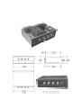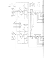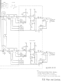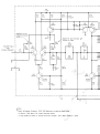
1
HP Archive
This vintage Hewlett Packard document was preserved
and distributed by
www.hparchive.com
Please visit us on the web !
Thanks to on-line curator: Kenneth Kuhn for supplying and
scanning this vintage document.
(j~ ~
,.
AMPUFIER
==========
Table of Contents
The Barney Oliver Audio Amplifier
TABLE OF CONTENTS
Page
Section
I.
II.
III.
DESCRIPTION
A. General
B. Specifications
1-1
1-2
FRONT PANEL CONTROLS
A. INPUT Selector
B. MODE Switch. .
C. FILTER Switch .
D. VOLUME Control
E.
Phono Equalization Switch (-6dB, RIAA, +6dB)
F. BASS Switch (FLAT, BOOST) . . . . . . .
2-1
2-1
2-1
2-1
2-2
2-2
INSTALLATION
A. Phono Connections
.
B. Use of Phonograph Pickups Other Than Shure V-15 Type II
C. Speaker Connections . . . . . . . .
D. Speaker Placement . . . . . . . . . .
E.
Line Voltage, Frequency and Line Fusing .
F. 115/230 Volt Amplifiers (European Units) .
G. Installing Amplifier in an Existing Cabinet
H. Assembly of Walnut or Teak Enclosure
I. Rack Mounting Cabinet . .
J.
Pictures and Outline Drawing
3-1
3-2
3-2
3-2
3-3
3-3
3-3
3-3
3-4
3-4
IV.
LOUDSPEAKER PHASING
4-1
v
CIRCUIT DESCRIPTIONS
A. Phono Pre-Amplifier
B.
Filter Board
C. Power Amplifier
D. Power Supply .
5-1
5-1
5-2
5-2
VI.
VII.
CIRCUIT DIAGRAMS
A. Phono Pre-Amplifier
B. Filter and Controls .
C. Power Amplifier one Channel
Dl. Power Supply . . . . . .
D2. Primary Circuits . . . . .
E;
Deck Wiring (See Sections VI, A, B, C, and D.)
PARTS LISTS
A. Phono Pre-Amplifier
B. Filter Board
C. Power Amplifier
D. Power Supply
E. Deck Parts . .
6-1
6-2
6-3
6-4
6-5
7-1
7-2
7-3
7-4
7-5
Description
The Barney Oliver Audio Amplifier
SECTION I
DESCRIPTION
A.
GENERAL
The Barney Oliver Amplifier is a high
quality all solid state audio amplifier designed for
two channel stereo sound reproduction in the
home, in studios, and in small to medium sized
auditoriums. It is intended for use with full frequency range 8 to 16 ohm speaker systems and
with signal sources (phonograph pickups, tape
decks, AM and FM tunners) that are themselves
flat enough to require little or no equalization. In
addition to the power amplifiers, the unit includes
phono preamplifiers designed to operate from any
of several magnetic phono cartridges. These preamplifiers provide the necessary equalization for
the RIAA recording characteristic. Additional plugin preamplifier boards have been designed for
direct moving coil microphone input or for direct
input from low-level, high impedance sources.
Adding this feature will require that the user build
the preamplifier boards, install and wire printed
circuit connectors in the deck, drill front or rear
panel holes as required, and modify selector switch
wiring.
Hum and distortion are inaudible. As a
result of careful attention to filtering and to lead
routing on printed circuit boards, the residual
hum is well below thermal noise (which itself has
been minimized by optimum input stage design).
The output stages of the amplifiers are operated
class-B to reduce standby power drain and are
biased and locally degenerated to reduce crossover
distortion. A large amount of overall negative feedback, ranging from over 100 dB loop gain at dc and
low frequencies to over 50 dB at the top of the
audio range further reduces any remaining harmonic and inter-modulation distortion. Since the
/-l-circuits are direct coupled, overload produces
no long time constant transients; the peaks are
simply clipped and the original waveform resumes
at its proper value immediately afterward. Because of the large amount of feedback, signals
only a fraction of a dB below actual overload
typically show a total distortion over 75 dB below
the fundamental.
Bridged-tee networks in the 8-circuits of the
amplifiers, and active filters in the mixing and
control board, enable the low-end response to be
maintained down to 20 Hz and to fall off very
rapidly below the audible range. This prevents the
amplifier and loudspeakers from being driven
beyond their linear excursions by low frequency
transients arising from such sources as warped
records or breath blasts into microphones. The high
end response is reduced at 18 dB per octave above
20 kc by another pair of active filters to protect
the amplifiers against overload by, or rectification
of, strong r-f signals.
The power amplifiers are protected against
damage from accidental short-circuits at their outputs. Momentary shorts will have no effect, But
sustained shorts may blow one or more of the protective fuses. In addition, all power supply outputs
are either current limited or fused so that shorts
from test probes will in general cause no damage.
Finally, considerable effort was devoted to
reducing switching transients. A balanced build-up
and decay of power supply voltages and careful
balancing of function drops minimizes the turn-on
transients in the amplifiers. A slow turn-on in the
low voltage regulated supplies further reduces the
turn-on transient from the pre-amplifiers.
1-1
The Barney Oliver Audio Amplifier
Description
SPECIFICATIONS
OUTPUT PER CHANNEL
SPEAKER Z
FREQUENCY RESPONSE
+1
CONTINUOUS* AUDIO PEAK
16
::::::36 W
::::::90W
8
::::::50W
::::::160W
4
**
::::::80W
I
+1
+
iI
II~I"
h!I~~T
,OUT
: I' i
!
~ o+l-J+.11++
1"'-N~-+----==t"'+-++----1I--+-+++-""'od-.=-+-+-I_+____1
i
! : I
I
'\
I
~
I!
~ -51 f
< 0.01%, 2 mw to max. power, all freqs.
~~
1
~~!\ ... 1\.
.
~
-'-+1-++----+---+----+-++----1-+-+-+-Hf ~
~I~-
II
HARMONIC DISTORTION
I
I
Ii: i
I I
Frequency Response
m
\
-101+1
1/
1
I
i
I
\
!\
-1~t--+-+++_-+--+----+-++-_I1__+-+_+_1_+_\h...._+___+_I_1_+____1
: Iii
HUM AND NOISE
Power Amplifier: 100 db below max. output
t Phono Preamp: 84 db below one volt output
~o
-1010
100
~oo
1000
~I
\Ir\~
lrr
~I
1001
FREQUENCY
INPUT VOLTAGE FOR FULL OUTPUT
Tuner, Tape, Aux 1, Aux 2:
Phono: ~ 5 mv rms
~1.0
volt rms
INPUT IMPEDANCE
Tuner, Tape, Aux 1, Aux 2: 100 K n
Phono: Optimized for SHURE V-15 Type II
Pickup.
CONTROLS
INPUT: TUNER, TAPE, PHONO, AUX 1,
AUX 2.
MODE:
STEREO - DIR(ect), REV(erse), L, R
MONO-DUAL, L, R
*Both channels operating simultaneously at
maximum output.
**Continuous high power operation at less
than 8 n not recommended. See instruction
manual.
t Hum pickup by phono cartridge may cause
this figure to be exceeded.
1-2
CONTROLS (Cont'd.)
FILTER: Controls active h.f roll-off filter
> 18 dB/octave with comer at 5, 8, 10 or
20 kHz. Includes 30 dB notch at 10 kHz
in 5 and 8 kHz positions.
VOLUME: Dual precision attenuator, 60 dB
range, 2 dB steps. Eliminates need for
balance control.
BASS: FLAT, BOOST
Response:
RIAA, + 6 dB, - 6 dB
SIZE:
16.72" (425 mm) wide, 5.0" (127 mm) high,
10.93" (278 mm) deep behind panel.
WEIGHT
Approximately 20 pounds net without case.
POWER REQUIREMENTS
115 or 230 V.A.C. ± 10%, 50-60 Hz, 20 W
standby power, 135 W at full output into
16 n (both channels).
Front Panel Controls
The Barney Oliver Audio Amplifier
SECTION II
FRONTPANELCONTROLS
Simplicity of operation has been achieved
with a minimum of controls. It is a good idea to
mark with a colored dot the "normal" settings of
special purpose controls so that the inexperienced
or technically naive operator need only ch-eck these
settings and achieve good results using only the
input selector and volume control.
A.
DUAL
Both channels mixed and delivered to both speakers.
L
Monophonic
reproduction of
"left" channel over both speakers.
R
Monophonic
reproduction of
"right" channel
over both
speakers.
INPUT Selector
This switch allows a choice of anyone of
five inputs. From left to right these are:
TUNER
Accepts input at line level (0
dBm) from FM, AM, or FM/AM
tuner.
TAPE
Accepts input at line level (0
dBm) from an equalized stereo
or single channel tape deck.
PHONO
Accepts input from a magnetic
stereo phonograph pickup.
AUX 1
Accepts inputs from any linelevel audio circuit such as tuners,
tape decks or other sources.
AUX2
B.
The Land R positions allow monophonic
tapes and other signal sources to be reproduced
over either one (STEREO side) or both (MONO
side) speakers.
C.
FILTER Switch
This control allows various high frequency
roll-offs to be introduced. From left to right the
positions are:
5
Introduces a high frequency cutoff at 5 kHz, with a null at 10
kHz. Useful for noisy 78 rpm
records and AM reception.
8
Introduces a high frequency cutoff at 8 kHz with a null at 10
kHz. Useful for good 78 rpm
records and AM reception.
10
Introduces a maximally flat 18
dB/octave cutoff at 10 kHz. Useful for slightly noisy conditions.
20
Normal position. Introduces a
maximally flat 18 dB/octave cutoff at 20 kHz.
MODE Switch
This control allows the left and right channels of the input to be delivered to the speakers
in various ways. The center position is normal for
stereo operation. From left to right the modes are:
L
Left stereo channel only to left
speaker.
R
Right stereo channel only to
right speaker.
REV
Stereo channels reversed. Left
channel to right speaker, right
channel to left speaker.
D.
DIR
Direct presentation. Each stereo
channel to corresponding speaker
-Normal position.
VOLUME Control
A dual precision attenuator allows adjustment of the sound level in 2 dB (or scarcely
perceptible) steps over a 60 dB range. Because
the attenuation is precisely balanced and because
the feedback assures equal gain in both channels,
the nuisance and hazard of an improperly set
2-1
Front Panel Controls
balance control are eliminated. (Note: Identical
speakers are assumed. Good quality speakers of
good manufacture will ordinarily be within 1 dB
of each other over the audio range. Likewise for
the two channels of a good phono-cartridge. However, the perfectionist may want to test his
components and introduce appropriate loss into
the "hot" side.)
The Barney Oliver Audio Amplifier
enhance the high end to compensate for the
deficiencies of the usual playback system. If your
speakers are flat, the -6 dB position will help
correct this practice. If you find the +6 dB position
better in the majority of cases, your speakers (or
your ears) need attention.
F.
E.
Phono Equalization Switch (-6 dB, RIAA,
+6 dB)
Below the INPUT selector control, and effective only in the PHONO position of that control,
a three-position slide switch allows some compensation for recording defects. In the center (Normal) position, this switch provides the standard
RIAA equalization. In the left position, the high
frequency response is dropped by 6 dB, while in
the right position, the response is enhanced by
6 dB. Some manufacturers (such as Deutsche
Gramophone) conscientiously adhere to RIAA specifications, while others (names supplied on request)
2-2
BASS Switch (FLAT, BOOST)
Located below the high frequency FILTER
control is the two-position BASS switch. In the
BOOST position, the switch raises the response at
6 dB/octave from 80 Hz down to 20 Hz. In the
BOOST position, approximate compensation is
provided for the usual low-end roll-off of good
speakers. (Two poles at 40 - 50 Hz). If you are
fortunate enough to have an overdamped pair of
woofers with real poles at 80 Hz and 20 Hz (such
as LE-15A's or ALTEC 411-A's in 9 cu. ft. or
larger enclosures), the BOOST position will closely
compensate the low-end roll-off down to the
bottom of the audio range. For very high sound
levels, the FLAT position is recommended.
Installation
The Barney Oliver Audio Amplifier
SECTION III
INSTALLATION
A.
PHONO CONNECTIONS
Special precautions must be observed for
the PHONO input. Because a combination of shunt
and series feedback is used to control the impedance faced by the cartridge and thereby produce
the high end roll-off required by the RIAA recording characteristic, the "LOW" side of each input
is not grounded inside the amplifier and THESE
MUST NOT BE GROUNDED OR CONNECTED
TOGETHER externally. (See Section V, A. for
further information.) If coaxial or shielded wires
are used for each channel, the two inner shields
TO GROUND CONNECTION
ON REAR Of AMPLIfiER
NOTE:
must be insulated from each other and from the
outer shield around both as shown in Figure l.
In some cartridges, the LOW side of one or both
channels is grounded to the case by a thin strap
at one or both LOW terminals. IF PRESENT,
THESE GROUNDING STRAPS MUST BE REMOVED BY PRYING THEM OUT AND OFF
WITH A LARGE NEEDLE OR PICK. The overall
shield should be connected to the turntable frame
at one end and to the amplifier chassis at the other
end using the binding post provided. After this is
done, test that both channels are isolated from
ground before connecting them to the amplifier.
TO CHASSIS Of TURNTABLE
OR CHANGER
lead connecting pickup to amplifier (including
inner shields).
Inner shields must not be grounded at either
end. Also inner shields must not be connected
together at any point (including at or inside
pickup). Cables should have insulation over shields.
Outer' shield must not make contact with any
In some locations the outer shield may not be
necessary; in such cases, turntable or changer
chassis should be connected to amplifier chassis
(ground terminal on rear) with a separate wire,
preferably insulated.
Figure 1. Phono Connections
3-1
Installation
The Barney Oliver Audio Amplifier
The phono cartridge should be located as far
as is convenient from any transformers, motors, or
other source of AC magnetic field. With proper
installation and a good cartridge, no AC hum
should be audible even at the full setting of the
volume control and with bass boost.
B.
USE OF PHONOGRAPH PICKUPS OTHER
THAN SHURE V15 TYPE II
The phonograph pre-amplifiers as shipped
are optimized for the Shure V15 Type II pickup.
Other good quality pickups can be used, but a
resistor change on each of the phono pre-amp
boards may be required. The resistors in question
are designated R1 as shown near the left side of
the pre-amp schematic in Section VI, A. To
determine the optimum value for R1 for a given
pickup, the inductance and resistance of the pickup must be known. The value for resistor R1 may
then be calculated by using the following equation:
r\
L
6
~
\R 1 =_0_ x 10 - 100 R - 20K
.75
0
Where L o is pickup inductance in Henries, R o is
pickup internal resistance in ohms, and R1 is in
ohms.
Once the value for R1 has been calculated
R1 resistors on each of the two phono pre-amJ
boards should be changed to the proper value. For
additional information, see Section V, A.
LEFT SPEAKER
C.
SPEAKER CONNECTIONS
The amplifier may be located at any convenient distance from the loudspeakers. Twisted
pairs of No. 18 wire or larger or ordinary zip-cord
may be used to connect the amplifiers to the
speakers if the distance is under 100 feet. For
longer distances, heavier conductors are recommended. In general the d-c resistance of the
cables or cords should not exceed 5% of the
speaker impedance.
Connection to the amplifier outputs is via
the two-terminal polarized Jones sockets at the
rear of the amplifier. The cords or cables must be
soldered to the mating plugs provided, taking care
to avoid internal short circuits from wire strands
or solder bridges. It is good practice to insulate
the wire and lugs from each other with electrical
tape or heat shrinkable tubing inside the plug
sleeve after soldering.
D.
SPEAKER PLACEMENT
The loudspeakers should be located at the
ends of the base of an isosceles triangle with the
listener at the apex. The apex angle of this triangle, i.e., the angle between the lines of sight
to the two speakers should be about 15 0 to 45 0 ,
as shown in Figure 2. Good sound quality will
then be heard up to 45 0 on either side of the
perpendicular bisector of the line between the
speakers.
RIGHT SPEAKER
~~~~
I
I
I
I
I
I
I
I
3-2
Figure 2.
Installa.tion
The Barney Oliver Audio Amplifier
E.
LINE VOLTAGE, FREQUENCY AND LINE
FUSING
G.
INSTALLING AMPLIFIER IN AN EXISTING CABINET
115V/230V AMPLIFIERS (European Units)
If the amplifier is to be installed in an existing cabinet, careful attention should be paid to
the outline drawing shown in Sect~op III, J.
Because certain components, especially the power
supply capacitors, are quite large, it will be seen
that the overhang at the top of the front panel
is not very great and at the bottom edge is virtulllly
zero. This will require considerable care in cutting
the necessary hole in the cabinet. It is strongly
recommended that the amplifier be examined in
detail before laying out this hole to prevent costly
mistakes. Referring to the side view in the outline drawing in Section III, J., it will be seen that
overall front panel height is 5", that the rear panel
height is 4.85", and that the side gussets 'are 4.48"
high. This will make possible the use of a hole
somewhat less than 4.85" high, if the amplifier
can be tipped slightly as it is inserted.
Units shipped to Europe (and in a few cases
within the United States) are equipped with
115/230V power transformers.
Front panel overhang at each side is approximately 1,4", requiring less precision in the horizontal dimension.
Unless specifically tagged otherwise, amplifiers
operate only on 115V ac line. 115V amplifiers
have single power transformer primaries and cannot
be connected for 230V operation. (An external
230-115V step-down transformer may be used.)
The proper line fuse for 115V units is 1.6 amp,
slow-blow.
Satisfactory operation will be obtained with
line voltages within ±10% of the nominal (115V
or 230V) value. The line frequency should be
50 Hz or greater. A grounding or three wire socket
is recommended but not essential. If the chassis
is not grounded through the power cord, a separate ground may be needed to get rid of hum on
phono, mike or other low level inputs.
F.
Units shipped to Europe will be connected for
230V operation and will be equipped with 0.8 amp
slow-blow fuses. Because of the variety of ac plugs
used, amplifiers shipped to Europe will not include
line cords. The line connector on the rear of the
amplifier is compatible with European line cords,
and it is assumed that the user can obtain the
proper cord. Units connected for 230 operation
will be prominently tagged.
115/230 V amplifiers shipped within the
United States will be connected for 115V operation,
will use 1.6 amp slow-blow fuses, and will be
equipped with standard line cords. These units
will be tagged to indicate 115/230 capability.
Amplifiers with 115/230V power transformers may be reconnected by the user for either line
voltage. 115V operation requires connecting the
two halves of the transformer primary in parallel;
for 230V, the two halves must be connected in
series.
-NOTEWhen reconnecting transformer primaries, care
must be taken to insure that windings are
connected in an "aiding sense" (instantaneous flux produced by both windings must
have the same polarity).
The line fuse must be changed when changing
the line voltage (1.6 amp for 115V; .8 amp for
230V).
H.
ASSEMBLY OF WALNUT OR TEAK ENCLOSURE
If the walnut or teak enclosure option was
included with your amplifier, it may be assembled
as outlined below. (See Section III, J. f~r picture
of assembled enclosure.)
The enclosure kit consists of the following:
Two wood side panels (one right and one left).
Black vinyl-clad aluminum top cover with
retaining screw.
Four 10-32 flat-head Allen screws and nuts
for attaching side panels to amplifier.
Wood side panels have been sanded but not
finished. It is recommended that the wood pieces
be finish sanded with fine sandpaper such as
400 or 600 grit. They can then be finished as you
please. One quick, simple and beautiful finish
which can be done by most anyone anywhere is
an oil finish, with or without stain. Most paint
stores and many hardware stores sell Danish oil
finish materials (one brand is Watco).
If a high-gloss finish is desired, it will be
necessary to apply filler to the wood before staining and applying finish. For this process the user
is referred to his friendly paint store or cabinet
shop.
3-3
The Barney Oliver Audio Amplifier
Installation
ASSEMBLY INSTRUCTIONS
Attach the wood side panels to the amplifier
with the Allen screws and nuts. It will be noted
that the side panels are notched across one end
to clear the front panel overhang and to allow the
wood panel to extend slightly forward of the
front panel. Near one edge of each wood panel
is a slot extending the full length. The panel should
be attached so that these slots are at the top of the
amplifier and face inboard.
The aluminum top cover slides into the slots
just mentioned, with the front edge fitting into a
slot at the top rear of the front panel.
screw through the top cover. It may be necessary
to adjust the positions of the wood side panels to
permit the top cover to slide into place without
interference from side gussets or other amplifier
parts.
I.
If your amplifier was furnished in an HP
type cabinet, it can be rack mounted by use of
the standard rack mount kit shipped with the
instrument. Instructions are included with the kit.
J.
The rear edge of the top cover lies on the
top of the back panel and is secured with a single
3-4
RACK MOUNTING CABINET
PICTURES AND OUTLINE DRAWING
(See following page.)
. 3 8 i n ' i t - - - lo.93in.~
(10mm)
(278mm)
I
~~~~
I
i"
:
I
iIii
I
@
I
~:~;'~::i-----l
I
r
t
[lI(W~;:;:r
16.72 in.
(425mm)
I
_,12.11in.
(308mml--i
J
~
r
4.48in.
4.85in.
(114mm) (123mm)
5.00in.
(I27mm)
I
~---------+J------<.
0
c::::J
I
NOTE: CASE IS AN EXTRA·PRICE OPTION
The Barney Oliver Audio Amplifier
Loudspeaker Phasing
SECTION IV
LOUDSPEAKER PHASING
Proper stereo reproduction requires that the
loudspeakers be properly phased. To check this,
insert a reversing switch in the leads to one
speaker as shown in Figure 3. Turn on the power
and the signal sources and bring up the volume. Set
the MODE switch to "DUAL". Station yourself
exactly midway between the speakers and about
three feet in front of the plane of their front
baffles. Try reversing the switch. In the proper
position the sound should appear to originate from
dead ahead of you. In the improper position this
illusion disappears and both sources are heard
independently. Unless the speakers are matched,
the above test is difficult,' but with identical
speakers the illusion is very striking and the test
is easy to perform. Reconnect the speaker pre-
serving the proper polarity. This test need only
be done once. Return the MODE switch to the
normal STEREO-DIRECT position.
If, on the average, one channel seems louder
than the other, throw the MODE switch to the
STEREO-REVERSE position. If the loud channel
shifts to the opposite speaker the signal source or
program material is defective. If the loud channel
stays with the same speaker, the other speaker is
less efficient. If the speakers are supposedly
identical, the weak one may be defective. (Check
the doc resistance of the speakers. These should
be the same within 5%.) The use of different
speakers for the two channels is not recommended.
AMPLIFIER
Note: dl must equal d2
Figure 3.
4-1
Circuit Description
The Barney Oliver Audio Amplifier
SECTION V
CIRCUIT DESCRIPTIONS
A.
PHONO-PRE-AMPLIFIER
The phono pre-amplifier uses a combination of series and shunt feedback to the input
terminals to provide a resistive input impedance
of the proper value to produce, together with the
self inductance of the pickup, the required RIAA
high frequency roll-off above 2120 Hz. If L o is
the pickup inductance and R o the resistance, and
if R is the input resistance to the pre-amp we
require that
L
6
R +oR = 75 x 10- seconds
o
This leads to the value of R1 given in the schematic. As supplied, R1 is appropriate for the
Shure V-15 Type II cartridge. To provide the ±6 dB
variation of high end response, the shunt feedback is halved or doubled.
The series feedback is applied to the low end
of the pickup windings which places these ends
(normally the outer shields of coaxial lines) 10 n
above ground. To avoid hum and RF pickup it is
recommended that an outer shield insulated from
both inner shields be used. This shield should
connect the record player frame to the amplifier
chassis.
A balanced differential stage is used at the
input to avoid drift and RF rectification. The
remainder of the amplifier is similar to the power
amplifier except for power level. The output Class
B stage can supply a 600 n line or headphones
at line level (0 dBm) without appreciable distortion.
The low end bass boost of the RIAA characteristic below 500 Hz is provided by C12 and R3
+ R4 + R5 + R6 and R28. The low end cutoff is
provided by C2 and C3 together with C4, C5 and
R10. This combination provides unity d-c external
gain and a fourth order maximally flat low-end
cutoff at about 16 to 20 Hz.
Great care was used to make the projected
area of the input circuit zero in all directions by
properly routing the conductors and by providing
the loops shown. This minimizes the magnetic
coupling to the power transformer and reduces
the hum below audibility. (If you notice any
hum, it's from coupling directly to the cartridge.)
Because the input impedance is low (about
10 K n ) cable capacitance has no effect on the
high end response for lengths up to 10 or 20 feet
depending on the cable used.
Many of the components that may puzzle
you, such as Q3 or CR8 or such as CR1, CR2,
CR5, etc., are there to avoid tum on transients or
avoid emitter base breakdown. Everything has a
function, but invincible fatigue prevents me from
going into all the gory details.
B.
FILTER BOARD
The filter board provides a sharp low-end
cutoff below 16 Hz to protect the speakers
against large useless cone exursions, and a controllable high-end cutoff to suppress the high frequencies with noisy or distorted program material.
The board contains four unity gain amplifiers
consisting of two cascaded emitter followers (example: Q3 and Q5) with constant current supplies
(example: Q1 and Q7). This combination provides
very high input impedance, very low output impedance and low distortion.
The two input unity gain amplifiers are
coupled to the input selector switch through active
high pass filters that drop rapidly in transmission
below 16 Hz (example: C1, R1, C3, R7, Q3, Q5).
The output of these feed the mode selector switch.
The output unity gain amplifiers provide
drive for the dual precision volume control and
are coupled to the mode selector switch via active
low-pass filters. These are three pole filters, two
of the poles being provided by the input RC networks and the remaining poles (and zeros) by the
shunt branch at the output.
Potentiometers are provided to supply the
base currents of the input emitter followers and
thereby enable the voltages at terminals 5, 4, 20
and 21 to be set equal to zero. This eliminates
transients when the mode and filter switches are
switched.
5-1
The Barney Oliver Audio Amplifier
Circuit Description
C.
POWER AMPLIFIER
The output stage of the power amplifier is
a cascaded complementary emitter follower comprising transistors Q12* and Q13*, with QlO and
Qll as their drivers. Operating point stability is
provided by resistors R5* and R6* and by currents
from current source Q8 flowing through CR7,
CR9, R22, CR8 and CR6. The power diodes CRI *
and CR2* shunt R5* and R6* at high signal levels
to avoid large voltage drops in these resistors.
Inductance Ll * protects the output stages from
the effects of capacitive cable loads at very high
frequencies while R8* eliminates any series resonance with this capacity. Diodes CRlO, CRll, CR12
and CR13 provide output current limitation. Together with fuses F* these provide output short
circuit protection. The output stages are driven
by emitter follower Q9, which has current limitation in the collector.
The input stage consists of a differential pair,
Ql and Q2, whose emitter currents are supplied by
Q4. The input signal is applied to the base of Ql
and the feedback to the base of Q2. The output
collector swing of Ql is limited by CR2 and CR3
to protect the emitter-base junctions of the second
stage comprising Q5 and Q7.
The loop gain at d-c and low frequencies is
extremely high (> 100 dB). The primary cutoff
for the loop gain at high frequencies is the basecollector capacitance of Q7. Thus the loop gain
falls at 6 dB/octave to reach a value of about 60
dB at 10 kHz. Inductors Ll and L2 introduce a
second pole at 16 kHz above which the loop gain
falls at 12 dB/octave to about 200 kHz, where
C6 begins to shunt R16 producing a high end cutoff in the amplifier and reducing the loop gain
cutoff rate to 6 dB/octave once more. Gain
crossover is at about 1 MHz.
The bridged-T comprising C3, C4, Rll, and
R12 increases the loop gain below 16 Hz and
reduces the external gain to unity at d-c. The
poles in the external gain are slightly complex so
the low end response rises slightly at the low end
before dropping off. In the bass-boost position
C7 and C8 together with R16 and R17 produce
a pole at 16 Hz and a zero at 80 Hz in the external
gain. Thus the gain rises at 6 dB/octave below 80
Hz, to compensate for the low end roll-off of
most loudspeakers.
"Located on chassis. See rfghthand portion of Power Amplifier
Schematic. Section VI. C.
5-2
Transistor Q3 supplies current to two potentiometers R4 and R5, which are adjusted so that
the currents through R2 and R3 supply the base
currents of Ql and Q2. By adjusting R5 with the
input terminals shorted (volume control at minimum) and R4 with the input terminals open (or
with the volume control at maximum) to give
zero volts out of the amplifier, this condition will
hold for any impedance the amplifier faces (any
volume control setting).
D.
POWER SUPPLY
All supply voltages (50V, 40V, 20V and lOY)
are available in both polarities. The main supply
(± 40V) is rectified by diodes CRl, CR2, CR3,
and CR4 in a double full wave configuration.
Filtering is by capacitors C3 and C4. This supply
has a substantial amount of ripple, especially under
load, but the power amplifier by-passing is such
that this produces negligible hum in the amplifier
output.
-WARNINGThe terminals and leads of C3 and C4 are
not current protected. Do not short to
ground or to each other. (You'll ruin your
screwdriver. )
The +50V supplies are really 10V supplies
floated on the +40V supplies respectively. They
will show about the same ripple as the latter. Transistors Ql and Q2 with their associated circuitry
provide protective current limits on the +50V
supplies.
Zener diodes CR13 and CR14 establish the
reference voltages for the ± 20V supplies obtained
from the cascaded emitter followers Q3-Q5, and
Q4-Q6. The rate of rise and fall of these supplies
during tum on and turn off is determined by the
two stage active filters comprising R9, C5, R13
and R15, C7 and transistor Q3 for the + 20V
supply and RIO, C6, R14 and R16, C8, and
transistor Q4 for the -20 V supply. Diode CR17
compensates for junction drops in Q5 and Q7,
while CR18 compensates for junction drops in
Q6 and Q8. Resistors Rll and R12 compensate
for the initial charging currents in C5 and C6 so
that these currents do not flow through R17, R19,
CR17 and R18, R20, CR18.
The Barney Oliver Audio Amplifier
Resistors R17 and R19 as well as R18 and
R20 are dividers to develop the ± 10V reference.
The ± 10V outputs are taken from emitter
followers Q7 and Q8.
CR15 and CR16 provide short circuit protection and transistors Q9 and QI0 protect the
emitters of Q7 and Q8 against reverse voltage
from shorts between the 10 and 20 volt supplies.
Circuit Description
The 10 and 20 volt supplies are regulated and
essentially ripple free.
The maximum steady current ratings of the
various supplies are:
Max Current
Supply
18 ma
±10V
70ma
±20V
3 amps
±40V
0.5 amps
±50V
5-3
SECTION VI
CIRCUIT DIAGRAMS
r-------------------·
I
03
3-020
I
I
I
I
I
I
+
C6
15fL
R7
lOOK
RS
lOOK
CRl
1-040
CR2
1-040
=
4-221
I
La
Rl
02
01
4-221
SHURE V15 ETC.
I
I
I
I
I
I
I
909K
CR3
1-040
CR4
1-040
C1
30pF
3
4
I
Q4
4-071
R2
20K
R9
46.4K
54
-6db
16
I
I
I
I
I
I
I
I
I
I
I
I
I
L
R4
511.n.
R3
1100n
R5
511.n.
R6
lOon
C2
300J-LF
NP
300~~
LOOP
C3
-=
.
- - --- -- - -- - - - - - - - - - - ---- - -- - - - - - - - - -----.,I
03
3-020
I
I
RI9
215.n.
11
~~-"'--"'-----""----~~-_.-IVv'\----"""1,,",""----------o+20V
I
+
R15
26.1K
Rll
5.11K
05
3-020
R7
lOOK
I
R23
511,(1
I
I
07
3-020
I
I
I
I
RS
lOOK
CR1
1-040
I
I
I
I
Cll
T 1000pF
-=
09
4-071
CR2
1-040
01
4-221
02
4-221
I
I
I
RI3
10K
CR4
1-040
I
R25
51.1.fl.
CR7
1-040
CR3
1-040
I
I
011
4-071
R22
10K
R17
200.0.
17
I
1
R29
5.11 K
18
010
3-020
CR8
1-040
I
I
I
I
08
4-071
4-071
06
4-071
R12
5.llK
R9
46.4K
+
R16
56.2K
OUTPUT TO SELECTOR
SWITCH
I
R26
51. 1.fl.
CR6
1-040
Q4
I
R27
51.1.fl.
I
I
I
R1S
10K
C10
TIOOO
pF
-=
R24
511.fl.
Cl2
.15fLF
I
I
I
R2S
21.5K
I
R20
215.0.
17
....----+-....--+-----....- - - - -....---'VV'V---....----+-----OO -20V
R6
10.0.
R14
120K
I
I
I
LOOP
tl
RIO
20.0.
C3
300~~
LOOP
I
I
-=
-=
I
I
I
I
_ _ _ _ _ _ _ _ _ _ _ _ _ _ _ _ _ _ _ _ _ _ _ _ _ _ _ _ _ _ _ _ _ _ _ _ _ _ _ _ _ _ _ _ _ JI
x 10 6 -IOOR o -20K
* R1 =...!:..2.
.75
L o IN H, R o IN .fl.
5mV PRODUCES 1 VOLT OUT AT 1KHz
ALL RESISTORS l/SW METAL FILM UNLESS OTHERWISE NOTED.
3ZIA Phono Preamplifier
1- - - - - - - - - - - - - - -
--~
I
I
I
I
I
I
I
PHONO
TAPE~AUX1
TU
NER-f
t L
51
AUX 2
~
~51A
I
2
~
R15
10K
OUTPUT
+IOV
+/OV
I
STERE0
I
I
I
I
I
R3
lOOK
[
L
1
iMONO]
51' ~~,
52
I
I
I
53
I
I
-IOV
I
Cl
.22
I
I
I
I
RI3
3.16K
1
1-..¢:5~+-+.J-:-~t-;:;-v:;:.:,JlVV\r~=:Y21
536 1
I
CII
I
.001:
r~l~
Rl
23.7K
~
10
I
I
I
1
I
I
I
I
-IOV
16 1
-20V
CI~
. 0181
L..---.-v-"""'jr
r
I CI7 .03:
14
22 1
-=
i--
I
I
I
I
I
I
I
I
I
I
I
I
TUNER
MONITOR
I
I
I
+20V
FILTER
MODE
INPUT
121
3
2*1
+
C5
10fLF
*1
+
10fLF
CI9.C
L..-----r-.....,r
+20V~C7
+/OV~I-~P-'
1
C8
~IOfLF
-/OV~+
I
C6
~IOfLF
-20V~+
RUMBLE FILTER
AND
BUFFER AMP
+20V
o
+/OV
o
0
I
I
I
I
~
~516
PHONO
~
TUNER
RI6
MONITOR 10K
OUTPUT
R4
lOOK
I +/OV~"""",,'V,,.-'V-IOV
I
I
1
I .g
I
1
I
I
I
1
I
1
F
I
I
I
I
1
R2
23.7K
I
R14
1
1
1
1.96K
CI2
1
Cl'
.0012
r
I
I
L
-IOV
-20V
I
---I:
151C18 .O~
I
I
I
I C20 .01
I
L-
I
IIL
I
o~~
I
I
I
I
53EI
I
_
f
13
J
_
_
FILTER
MODE
51' «,
STERE0
[
1
iMONO]
--1
r - - - - - -- - - -- -- - - - - - -
I
1
52
S3
I
I
+IOV
+ IOV
I
I
+20V
I
1
1
1
1
I
1.96K
RI9
lOOK
1
I
I
R23
I
I
RI5
4.7M
I
3R!~K
211
I~~.n.-IOV
--'\I\I'v-+-~---+-V-./'v-f'--+1
I
:-.......+6-O-+-....:vVv--......
I
4
S3BI
S3A
I
Cll
lO~r"'
10 1
CI3
.00125fl-F
C25 I
.0047fl-FI 9
CI5
.018fl-F
10K STEPPED
ATTENUATOR
rl-O--.....J
14 1 CI7.033fl-F
12 1
RIA
TO POWER AMP
1
1
I
I
S3C
I
ICI
.0047
I fl-F
t---+---JI t--'
16 1
*
*
*
1
5
C19 .01fl-F
-20V
-IOV
L-------.:..:<>--~I_. ...- - - - - - - - - - - - - -...
d~~
Ll
31.6mHl·uu
o
o 0
ACTIVE FILTER
+/OV
+/OV
+20V
R24
1.96K
R20
.---",IOOK
RI6
4.7M
RI4
3.16K
4
R18 -IOV
100.n.
20
S3D
lc2
.0047fl-F
I
I
I
I
17
1
10K STEPPED
ATTENUATOR
P
I
C26
.0047fl-F 110
*
pt---<?--.
...
.018fl-F
131 C20 .01fl-F
L..
RIB
TO POWER AMP
I
CI6
15'C18.033fl-F
-20V
-IOV
~(_-.,~-....- - - - - - - - - - - - - -....
_ _ _ _ _ _ _ _ _ _ _ _ _ _ _ _ _ _ _ ...1
S3F
'6*
.06~~~,d
L2
I
31.6mH
_
-
1
1
_ _ _ _ _ _ _ _ _ _ _ _ _ _ _ _ _ _ _ _ _ _ _ _ _ _ _ _ _ _ _ _ _ _ _ _ _ _ -.JI
PNP - 2N3906, 1853 -0036
NPN- 2N3904, 1854-0215
Notes:
This Boord Utilizes Two Separate Connectors. Terminals on
the Larger Connector are Lobled 1 thru 22; Terminals on
the Smaller Connector are Shown as 1* thru 10*.
All Resistors 1/8 W Metal Film Unless Otherwise Noted.
C27* and C28* Selected To Center 10 KHz Notch at 10KHz
± 100Hz
1ZI B Filter and Controls
,---------------------------------CR1
1-040
R6
10K
RIO
10K
R7
10K
+
RI3
5.11 K
R19
5.11K
C5
50f-LF
03
CR2
1-040
2N5401
05
CR3 2N5401
07
2N5401
Adjust for 0 V at
Output with Volume
'tF""~
Adjust for OV at Output with
Volume at Zero
R4
50K
Amplifier Input
from
Daven Attenuator
R5
C6
120pF
r -.....-<50K
R2
1.5M
2
I
R1
1/4w
51.1.0.
I
I
R16
5.l1K
R12
200.(1
11
-=
C8
.027f-LF
R17
20K
I
I
I
~
C3
T100f-LF
NP
-=
R15
34.8K
~
04
Current
Source
+
10-- - - - -
----
06
2N5551
2N5551
C2
50f-LF
"I
5.1 K
---------t---
.
NOTES:
/
•
--16
f~-
\
*Select for Speaker Protection 2.0A 3AG Maximum Located on Back Pl,(el.)/
All Resistors 1I8W Metal Film Unless Otherwise Noted.
4 - Digit Number by Diodes is Derived from Part Number: CR1
,
=190
J
J
40
--..1--------
=1-040
---------------------,
R27
_ _ _ _ _ _. .
I
I
100
........I'I'."""----¢13
.......-
+50V
RI9
5.IIK
05
o
CR3 2N5401
07
2N5401
R23
909.n.
These Parts on Chassis
Cl0
'Jl000pF
+40V
lDo---Cl
J5
)ut with
R26
10K
R22
75.0.
C7
.4 p.F
R2
1.96K
R7
.05n.
L1
Audio
Out
R8
J7, PI
51.1 n.
OV
R17
20K
o
CR4
1-040
CR8
CR6
-40V
06
2N5551
2N5551
R21 +
5.11K
J6
I
I
I
I
08
l:
!
50p.F
R28
100
I
!
5
:.....---~~-....- -....---4I....- -...---4I~--'\1/1\4I'W---'9-50V
I
I
-------------------------~
S5
~/::--~-----------------------_~
BOOST
~
FLAT
R9
lOOn.
1/2W
Phone
Jack
J8
1ZIC Power Amplifier
One Channel
p o - - - - - - - - - - - - -_.
I
01
I
2N4036
I
3~
I
I
I
I
Rl
10.11
CR9
I
I
I
I
CR5
750MA
T1
+
C1
350}.l-F
+
Notes:
Power Transformer Primary Circuit Shown for
115V Models Only. For 115/230V Models,
See :llI 02.
CRll
C2
350}.l-F
I
I
I
I
I
4 Digit Number By Diodes and Transistors
is Derived from Part Number: 01:: 1853-0045 = 3-045
I
I
I
All Resistors 1/8 W Metal Film Unless Otherwise Noted.
I
R·
26.
CRIO CR12
R2
10.0.
I
02
I
2N2405
4-352-
l - _. -
-
-
-
-
-
-
-
-
,.....---- - - - - - - - - - - - - - - I
-
- - -----,
I
--<j'+50V
- -- ---- - - -- - -
01
I
2N4036
)3;:.-. :0:::4.::5
I
I
I
I
I
R5
562.f1
Rl
10.f1
CR9
I
R3
26.1K
CRll
R7
562.f1
I
I
03
4-071
I
CR5
750MA
05
R9
23.7K
2N2405
4-352
" ) . , , 4 - - - - - -.....----<; +20V
+
Cl
350fl-F
R13
22K
+
CR15
9V
RI5
2K
+
C5
100fl-F
-
C7
100fl-F
R21
560
Cll
Tl000pF
R19
lK
R25
10K
07
2N2405
+40V
Rl1
42.2K
+
CR3
3A
b"'--..:.4...:-3;.:5~2. ...- - t _ - - Q + 10 V
R17
lK
CR13
21.5V
C3
15Kfl-F
09
CR17
C9
1000pF
2N4036
3-045
R23
10K
5\-.+--4--------.---,
ClO
1000pF
+
CR4
CRIB
C4
15Kfl-F
R12
42.2K
010
RIB
lK
2N2405
4-352
CR14
21.5V
\-----4....--I4---+---....--u -40V
R24
10K
.--L~--....- - - + - - - o - 1 0 V
08
R20
lK
+
+
_
R14
22K
C2
350fl-F
+
C6
100fl-F
-
R26
10K
CB
100fl-F
R16
2K
RIO
23.7K
I
I
I
..,.1~-----""---o-20V
06
2N4036
3-045
I
I
I
I
2N4036
3-045
R4
26.1K
CRIO CR12
R8
562.f1
R6
562.f1
R2
1O.n.
I
I
I
I
L-_. - - - - - - - - - -
02
'J----------------------------_~
-50V
I
2N2405
4-352--- -
.J
------ -----
1lI 01 Power Supply
56
r---l
FI
J4
2
3
I
O.SA S.B.
I
I
I
I
230 ±IO%V
50-400'V
Jl
RIO
47K
I
J2
J3
I
I
I
L
4
-....,
I
I
NE2
I
L.___
_.J
5
115V/230V CONNECTED FOR 230V OPERATION
56
r--i
3
FI
J4
2
I
I
I
I
I
I
I
I
±
115 lO%V
50-400'V
Jl
J2
L
1.6A S.B.
RIO
47K
J3
4
-...,
I
I
NE2
I
_..J
L ___
5
115V 1230V CONNECTED FOR 115V OPERATION
:ill 02 Primary Circuits
Parts List
The Barney Oliver Audio Amplifier
SECTION VII
PARTS LISTS
A.
PHONO PREAMPLIFIER
Description
Reference Designator
C1
C2,C3,C4,C5
C6,C7,C8,C9
C10, Cll
C12
CR1, CR2, CR3, CR4,
CR5, CR6, CR7, CR8
30pF mica
300 ~F np 3V
15 ~F 20V tantalum
1,000pF ceramic
.15 ~ F 10% mylar
0160-2199
30D1614
0180-1746
0150-0050
0160-0303
silicon diode
1901-0040
Q1, Q2
Q3
Q4
Q5
Q6
Q7
Q8,Q9
Q10
Qll
transistor npn
transistor pnp
transistor npn
transistor pnp
transistor npn
transistor pnp
transistor npn
transistor pnp
transistor npn
R1*
Value is dependent upon characteristics of the
phono pickup used. R1 = 909K for the Shure
V-15 Type II. Otherwise calculate R1 per
Section III, D.
20K
1l00n
5lln 1/8 W m.f.
10n
lOOK
46.4K
20n
5.llK
10K
120K
26.1K
56.2K
200n
10K
215n
10K
5lln
5l.1n
2l.5K
5.llK
R2
R3
R4,R5
R6
R7,R8
R9
R10
Rll, R12
R13
R14
R15
R16
R17
R18
R19, R20, R21
R22
R23, R24
R25, R26, R27
R28
R29, R30
Stock Number
X2N4044
(special)
X2N3904
(special)
X2N3904
(special)
X2N3904
(special)
X2N3904
1854-0221
1853-0020
1854-0071
1853-0020
1854-0071
1853-0020
1854-0071
1853-0020
1854-0071
0757-0195*
0757-0449
0757-0424
0757-0416
0757-0346
0757-0465
0698-3162
0757-0458
0757-0438
0757-0442
0757-0467
0698-3159
0757-0459
0757-0407
0757-0442
0698-3441
0757-0442
0757-0814
0757-0394
0757-0199
0757-0438
7-1
Parts List
The Barney Oliver Audio Amplifier
B FILTER BOARD
Reference Designation
7-2
Description
Stock Number
C1,C2,C3,C4
.221-' F mylar
0170-0086
C5,C6,C7,C8
10
0180-0374
C9,C10
100pF mica
0160-2204
Cll, C12
.00391.1- F mylar
0160-01~
C13,C14
.00125 1.1- F mylar
0160-0297
C15, C16
.0181.1- F mylar
0160-0302
C17,C18
.0331.1- F mylar
0160-0163
C19,C20
.011.1- F mylar
0160-0161
C21,C22
.001251.1- F mylar
0160-0297
C23,C24
.681.1- F mylar
0170-0039
C25,C26
.0047 F mylar
0160-0157
C27,C28
.00821.1- F mylar (See Schematic VI,B.)
0160-0160
L1,L2
Inductor, 31.6 mR
special
Q1, Q2, Q3, Q4
transistor pnp 2N3906
1853-0036
Q5, Q6, Q7, Q8 Q9
Q10, Qll, Q12
transistor npn 2N3904
1854-0215
Q13, Ql4, Q15, Q16
transistor pnp 2N3906
1853-0036
R1, R2
23.7K
0698-3158
R3,R4
lOOK pot
2100-2516
R5,R6
4.7 meg carbon
0684-4751
R7,R8
lOOK
0757-0465
R9, R10
lOOn carbon
0684-1011
Rll, R12
82.5K
0757-0463
R13,R14
1.96K
0698-0083
R15, R16
4.7 meg carbon
0684-4751
R17, R18
lOOn carbon
0684-1011
R19, R20
lOOK pot
2100-2516
R21, R22
82.5K
0757-0463
R23, R24
1.96K
0698-0083
R25, R26
4.64K
0698-3155
1.1-
F 20V electrolytic
The Barney Oliver Audio Amplifier
C
Parts List
POWER AMPLIFIER
Reference Designation
Description
Stock Number
C1
.01 ~ F ceramic
C2
50
C3
100JJ F 6V np
30D603
C4
22 JJ F tantalum
0180-0228
C5
50
C6
120pF mica
0160-2205
C7
.47~
0170-0064
C8
.027~
C9
36pF mica
0160-2308
C10
1,000pF ceramic
0150-0050
Cll, C12, C13
50 ~ F 50V electrolytic
0180-0141
silicon diode
1901-0040
L1,L2
220 JJ H inductor
9140-0129
Q1, Q2
transistor npn 2N5551
1854-0474
Q3
transistor pnp 2N5401
1853-0264
Q4
transistor npn 2N5551
1854-0474
Q5
transitor pnp 2N5401
1853-0264
Q6
transistor npn 2N5551
1854-0474
Q7
transistor pnp 2N5401
1853-0264
Q8,Q9
transistor npn 2N5551
1854-0474
Q10
transistor pnp 2N4036
1853-0045
R1
51.1n 1/8 w
0757-0394
R2,R3
1.5 meg 1/4 w carbon
0614-1551
R4,R5
50K pot
2100-2517
R6,R7
10K 1/8 w m.f.
0757-0442
R8
3.16K 1/8 w
0757-0297
R9
5.llK 1/8 w m.f.
0757-0438
R10
10K 1/8 w m.f.
0757-0442
Rll, R12
200 n 1/8 w m.f.
0757-0407
R13, R14
5.llK 1/8 w m.f.
0757-0438
R15
34.8K 1/8 w m.f.
0757-0123
CR1, CR2, CR3, CR4,
CR5, CR6, CR7, CR8,
CR9, CR10, CRll,
CR12, CR13
~
~
F 50V electrolytic
F 50V electrolytic
F
F
0150-0093
0180-0141
0180-0141
0170-0066
7-3
The Barney Oliver Audio Amplifier
Parts List
C.
POWER AMPLIFIER (Continued)
Reference Designation
Description
Stock Number
R16
5.llK 1/8 w m.f.
0757-0438
R17
20K 1/8 w m.f.
0757-0449
R18
10K 1/8 w m.f.
0757-0442
R19
5.llK 1/8 w m.f.
0757-0438
R20
20K 1/8 w m.f.
0757-0449
R21
5.llK 1/8 w m.f.
0757-0438
R22
R23
75 n 1/8 w m.f.
0757-0398
909n 1/8 w m.f.
0757-0422
R24
1.96K 1/8 w m.f.
0698-0083
R25
R26
R27, R28
lOOn 1/8 w m.f.
0757-0100
·0757-0442
D.
10K 1/8 w m.f.
loon 1/4 carbon 10%
0614-1011
POWER SUPPLY
Reference Designation
Description
Stock Number
C1,C2
350,u F 15V electrolytic
0180-2216
C3,C4
15000,u F 50V Sprague electrolytic
6821 Type 36D
153G050CC2A
C5,C6.C7,C8
100,u F 15V electrolytic
0180-0061
C9, C10, Cll, C12
1000pF ceramic
0150-0050
CR1, CR2, CR3, CR4
diode, rectifier 3 amp 100V
1901-0200
CR5, CR6, CR7, CR8
diode, rectifier % amp 100V
1901-0158
CR9, CR10, CRll,
CR12
diode, silicon
190t-0040
CR13, CR14
diode, Zener 21.5V
1902-3245
CR15, CR16
diode, Zener 9V
1902-3149
CR17, CR18
diode, silicon
1901-0040
Q1
Q2
transistor pnp 2N4036
transistor npn 2N2405
1853-0045
1854-0352
Q3
Q4
Q5
transistor npn X2N3904
transistor pnp (special)
1854-0071
transistor npn 2N2405
transistor pnp 2N4036
1853-0020
1854-0352
1853-0045
transistor npn 2N2405
1854-0352
Q8, Q9
transistor pnp 2N4036
1853-0045
Q10
transistor npn 2N2405
1854-0352
Q6
Q7
7-4
The Barney Oliver Audio Amplifier
D.
Parts List
POWER SUPPLY (Continued)
Description
Reference Designation
R1, R2
R3, R4
lOn
Stock Number
0757-0346
0698-3159
R5, R6, R7, R8
R9, R10
26.1K
562 n lh watt
0757-0815
23.7K
0698-31)58
R11, R12
42.2K
R13, R14
22K
0698-3450
0684-2231
R15, R16
1.96K
0698-0083
R17, R18, R19, R20
1K
0757-0280
R21, R22
562n lh watt
0757-0815
R23, R24, R25, R26
10K
0757-0442
E.
DECK PARTS
Reference Designation
Description
Stock Number
Cl,C2
.0047 I-' F
0160-0155
C3,C4
.01 J.L F ceramic disc cap
C5,C6
CR1, CR2
.01 J.L F mylar 200V
diodes Motorola MR 841
0150-0093
0160-0161
Fl
F2,F3
line fuse
1.6A slo-blo for 115V
.8A slo-blo for 230V
speaker fuses 2 amp max
2110-0005
2110-0020
2110-0003
Jl
AC power connector
1251-2357
J2,J3
J4
power receptacles
1251-2073
line fuse holder
1400-0084
nut
2950-0038
washer
2190-0068
J5, J6
fuse clips
1400-0008
J7
speaker output jack (mates with PI)
Cinch-Jones
S-202-B
J8
phono jack, ring tip sleeve
Switchcraft 12B
J9
phono preamp p.c. connector 18 pin
1251-0141
JI0
power amplifier p.c. connector 18 pin
1251-0141
J11
filter and control p.c. connector 27 pin
1251-0172
J12
filter and control p.c. connector 10 pin
1251-0166
JI3,JI4,JI5,JI6,
J17,J18
input jacks
fibre washers
1901-1038
GC Electronics
33-804
3050-0108
7-5
The Barney Oliver Audio Amplifier
Parts List
E.
DECK PARTS (Continued)
Description
Reference Designation
J19,J20
Stock Number
sockets for Q12, Q13
1200-0041
anodized insulators
1200-0043
~
inductor
P1
speaker output plug (mates with J7)
Cinch-Jones
P-202-CCT
Q12
power transistor pnp
Motorola
MJ4502
Q13
power transistor npn
Motorola
MJ802
R1 A& B
dual 10K stepped attenuator
Daven CPD-134M-H-4C687P
2dB/step with
detents
R2
R3, R4
1.96K
0698-0083
10rl2w
0698-3601
R5, R6
8.2rllh w
R7
.05rl
0699-0003
0811-1826
R8
51.1rllJ4 w
0757-1000
R9
0757-0198
R10
100rl h w
47K lAi w
R11, R12, R13, R14
3.16K, 1/8 w
0757-0279
R15, R16
10K 1/8 w
0757-0442
Sl
input switch
special
S2
mode switch
special
S3
S4
filter switch
phono equalization switch
special
3101-0106
S5
bass switch
off/on switch w/pilot lamp
3101-1235
3101-0100
power transformer
115Vonly
115/230V
5081-0876
5081-5280
S6
T1
7-6
13 Po H
special
L1
1
0684-4711
HEWLETT ;,./ip; PACKARD
t
L
.
,;j
7507 PoIgD Mill Road, Palo Alto, California 94304, Telephone 475493·7507, TWX 910]73 7267
FROM,
TO,
Dan Lansdon
DAlE
Barney Oliver Amplifier
Owner~BJECT
May 1973
Corrections to Amplifier Manual
The following corrections should be made to the Barney Olive r
Amplifier Manual.
Page
7-2
C11, C12
Part No. should read 0160-0156
Page 7-3
R2, H3
Part No. should read 0684-1551
Page 7-4
CR9, 10, 11, 12
Part No. should read 1901-0040
R27, R28
Part No. should read 0684-1011
Page 7-6
R10
Part No. should read 0684-4731
"
I
Be sure there is no connection between left and right speakers.
(Some existing systems lise a "cornman" lead,)
Be careful to avoid even momentary short-circuiting of the
speaker outputs or lead:;. Short circuits will blow speaker
fuses (located under the black cover on the rear of the amplifier),
If Il1 doubt, visu3.ll,r..}nspect these fuses (not with an ohmmeter).
If you hOive a liibnal SOlll'ce other lhun phono (I, c. tuner', tapt: Illllt,
audio oscillatol', elc.), try'it first - in any (or all. in turn) of
the follov,ing inputs on the I'ear of the amplifier: TUNER, TAPE,
AUX I, /lUX 2. fle sure the input switch is in a position
cOl'l'esponding to the input which is connected. A lso be sure the
mode switch is in the STEREO NOHMAL position.
If step 0 works out, then t;onnecl the phono pickUp leads (from
turntable or changer) to the phono inputs - hut first:
C.
D.
E.
F.
Be sure the pickUp (cartridge) has four independent
terminals, with no metal or" wire connection between
any two terminals 01' between any terminal and
the metallic case of the pickup. (See Section III A.)
Make sure that leads are well soldered to speaker plugs and
that there are no frayed wires or solder bridges between the
terminals. (An ohmmeter check is advisable after soldering
leads to plugs and before connecting leads to speakers.)
B.
1.
Be certain that speaker leads are well insulated. (Beware of
ancient "zip cord" which may be partially shorted.)
A.
If after you have cal'efully gone through step
with the admonitions and caveats in the instr
system still does not work, please try to ge
an electronic friend in your 3.rea. Since thi
on a Shoestring, we have no funds for troubl
except for major [:t'oblems (defective power
defective attenuataI', ete.) The likelihood o
vel'y small; on the other hand, if conscienti
H.
shooting in your area fail to achieve results,
touch with Dan Lansdon, -hp' Labs, Palo A
If your phono pickUp is other than a Shure V
sec Section III fl.
Connect the amplifier chassis (thu
panel) to the tUl'nlable or changer
many cases this can be done with a
wire. If you still notice hum when
selected, install an outer shield al'
from) the left and right channe,l lea
this ouler shield (only) tolhe ampl
screw and to the turntable a" chan
Section JII A. )
Make cerlain there are separate s
each side (channel) of the pickup (c
thel'e is no connection between lea
and right channel. (Som(; changers
shield; this will not work on this a
sure the leads and shie ids are nol ,
tUl'Otable or changer chassis -ortO
Some turntables 01' changers will h
G.
3.
2.
To insure the spectacular performance of which this fine instrument is capable, it is respectfully requested that you read the inst
carefully, especially Sections II, III and IV. Certain connections are critical. Unless Insll'uclions are followed meticulously, th
WON'T WORK AND COULD BE DAMAGED. To help you avoid pitfalls already encountered by some users, here are a few tips.
nA::~~L~V~~~~RE:A~~~~:R