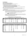
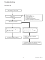
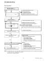
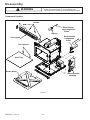
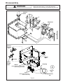
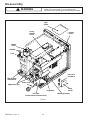
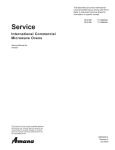
1
This Base Manual covers Commercial Microwave Ovens with 120/230 V, 50 Hz. Refer to individual Technical Sheet for information on specific models. This manual includes, but is not limited to the following: Service International Commercial Microwave Oven Service Manual for Amana® HDC511 HDC514 HDC518 DEC11E DEC14E DEC18E UC11E UC14E UC18E UHDC511 UHDC514 UHDC518 This manual is to be used by qualified appliance technicians only. Amana does not assume any responsibility for property damage or personal injury for improper service procedures done by an unqualified person. RS5320013 Revision 0 August 2000 Important Information Pride and workmanship go into every product to provide our customers with quality products. It is possible, however, that during its lifetime a product may require service. Products should be serviced only by a qualified service technician who is familiar with the safety procedures required in the repair and who is equipped with the proper tools, parts, testing instruments and the appropriate service manual. REVIEW ALL SERVICE INFORMATION IN THE APPROPRIATE SERVICE MANUAL BEFORE BEGINNING REPAIRS. Important Notices for Consumers and Servicers ! WARNING To avoid risk of serious injury or death, repairs should not be attempted by an unauthorized personnel, dangerous conditions (such as exposure to electrical shock) may result. ! CAUTION Amana will not be responsible for any injury or property damage from improper service procedures. If prefroming service on your own product, assume responsibility for any personal injury or property damage which may result. To locate an authorized servicer, please consult your telephone book or the dealer from whom you purchased this product. For further assistance, please contact: CONSUMER AFFAIRS DEPT. AMANA REFRIGERATION, INC. AMANA, IOWA 52204 OR CALL 1-319-622-5511 and ask for Consumer Affairs If outside the United States contact: AMANA ATTN: CONSUMER AFFAIRS DEPT 2800 220th Trail AMANA, IOWA 52204, USA Telephone: (319) 622-5511 Facsimile: (319) 622-2180 TELEX: 4330076 AMANA CABLE: "AMANA", AMANA, IOWA, USA Recognize Safety Symbols, Words, and Labels ! DANGER - DANGER Immediate hazards which WILL result in severe personal injury or death. ! WARNING WARNING - Hazards or unsafe practices which COULD result in severe personal injury or death. ! CAUTION CAUTION - Hazards or unsafe practices which COULD result in minor personal injury or product or property damage. RS5320013 Rev. 0 2 Important Product Information ! WARNING Precautions to be observed before and during servicing to avoid possible exposure to excessive microwave energy, or electrical shock disconnect power to oven. (A) Do not operate or allow oven to be operated with door open. (B) Make the following safety checks on all ovens to be serviced before activating the magnetron or other microwave source, and make repairs as necessary: • Interlock operation • Proper door closing • Seal and sealing surfaces (arcing, wear, and other damage) • Damage to or loosening of hinges and latches • Evidence of dropping or abuse (C) Before turning on microwave power for any service test or inspection within the microwave generating compartments, check the magnetron, waveguide or transmission line, and cavity for proper alignment, integrity, and connections. (D) Any defective or misadjusted components in the interlock, monitor, door seal, and microwave generation and transmission systems shall be repaired, replaced or adjusted by procedures described in this manual before oven is released to the consumer. (E) Check microwave leakage to verify compliance with the federal performance standard should be performed on each oven prior to release to the consumer. ! WARNING To avoid risk of electrical shock, injury, or death, make sure these earthing instructions are followed. Earthing Instructions ! WARNING Do not remove earthing prong when installing earthed appliance in a home or business that does not have three wire earthing receptacle, under no condition is earthing prong to be cut off or removed. It is the personal responsibility of the consumer to contact a qualified electrician and have properly earthed three prong wall receptacle installed in accordance with appropriate electrical codes Should a two prong adapter plug be required temporarily, it is the personal responsibility of the consumer to have it replaced with properly earthed three prong receptacle or the two prong adapter properly earthed by a qualified electrician in accordance with appropriate electrical codes. Servicing of Earthed Products The standard accepted color coding for earthing wires is GREEN or GREEN WITH YELLOW STRIPE. These earth leads are NOT to be used as current carrying conductors. It is extremely important that the technician replace any and all earths prior to completion of the service call. Under no condition should earth wire be left off causing a potential hazard to technicians and consumer. Wiring Good service practice is to never route wiring over terminals and/or sharp edges. This applies to any wiring without regard to the circuit voltage. Wire insulation material and thickness is designed and regulated for electrical spacing purpose only, but cannot always be relied upon because of possible cuts and/or abrasions, which can occur during servicing. Amana Appliances • 2800 220thTrail • Amana, Iowa • 52204-0001 • Printed in the U.S.A. 3 RS5320013 Rev. 0 Table of Contents Important Product Information ..................................... 2 Important Information .................................................. 3 Important Safety Information ....................................... 5 Product Information Antenna Blade ......................................................... 9 Blower/Fan Assembly .............................................. 9 Grease Shield .......................................................... 9 Door Interlock and Monitoring Switch ....................... 9 Auto Transformer ..................................................... 9 Transformer High Voltage ......................................... 9 High Voltage Capacitor ............................................ 9 High Voltage Diode (Rectifier) .................................. 9 Magnetron ............................................................... 9 Thermal Cutout Protectors ....................................... 9 Touch Panels ........................................................... 9 Triac ........................................................................ 9 Antenna Motor(s) ..................................................... 9 Installation Unpacking Oven .................................................... 10 Oven Placement .................................................... 10 Radio Interference .................................................. 10 Grounding Instructions ........................................... 10 Care and Cleaning Changing Oven Light Bulb ...................................... 11 Cleaning Interior, Exterior, and Door ....................... 11 Cleaning Splatter Shield ........................................ 11 Cleaning Air Intake Filter ....................................... 12 Cleaning Discharge Air Vents ................................ 12 Control Panel Features ............................................. 13 Displays Cooking Methods ................................................... 14 Cooking Displays ................................................... 14 Programming Displays ........................................... 14 Operation Interrupting Operation ............................................ 15 Canceling Mistakes ............................................... 15 Operating Preprogrammed Pads ............................ 15 Using X2 Pad ......................................................... 15 Manual Time Entry ................................................ 15 Programming Instructions Memory Pads ........................................................ 16 Multiple Cooking Stages ........................................ 16 X2 Quantity Feature ............................................... 16 User Options ......................................................... 17 Component Testing Procedures ................................ 18 Test Modes Power Test............................................................. 21 RS5320013 Rev. 0 Microwave Energy Leakage Testing Equipment ............................................................. 22 Procedure for Measuring Radiation Leakage .......... 22 Measurement With the Outer Case Removed ........ 22 Measurement With a Fully Assembled Oven ......... 22 Record Keeping and Notification After Measurement ................................................ 22 Troubleshooting Initial Power Up .................................................. 23 Standby Condition .............................................. 24 Cook Condition ................................................... 25 Disassembly Door Removal ........................................................ 26 Inner Door/Window Removal .................................. 26 Door Disassembly ................................................. 26 Door Handle ........................................................... 26 Hinge ..................................................................... 26 Interlock Switch Replacement/DoorAdjustment ..... 27 Outer Case ............................................................ 28 Back Panel ............................................................ 28 Grease Shield ........................................................ 28 Antenna Assembly–Top ......................................... 28 Antenna Motor–Top ................................................ 28 Oven Tray Removal ................................................ 28 Antenna Assembly–Bottom ................................... 28 Antenna Motor–Bottom .......................................... 29 Touch Panel Assembly .......................................... 29 Control Board ........................................................ 29 Interlock Switch Assembly .................................... 29 Magnetron Cutout (TCO) ........................................ 29 Triac ...................................................................... 29 Diodes ................................................................... 29 Magnetron ............................................................. 30 Cavity Thermal Cutout Replacement ...................... 30 Fuse ...................................................................... 30 Blower Wheel and Motor ........................................ 30 Fan Blade .............................................................. 31 Line Filter .............................................................. 31 Auto Transformer ................................................... 31 High Voltage Transformer ....................................... 31 Capacitor ............................................................... 31 Power Cord ............................................................ 31 Lamp Receptacle ................................................... 31 Replacing Oven Lamp ............................................ 31 Component Location Figure 1 .............................................................. 32 Figure 2 .............................................................. 33 Figure 3 .............................................................. 34 4 Important Safety Information 5 RS5320013 Rev. 0 Important Safety Information RS5320013 Rev. 0 6 Important Safety Information 7 RS5320013 Rev. 0 Important Safety Information ! 7. In the area of the transformer, capacitor, diode, and magnetron there is HIGH VOLTAGE. When the unit is operating, keep this area clean and free of anything which could possibly cause an arc or earthing, etc. 8. Do not for any reason defeat the interlock switches. There is no valid reason for this action at any time; nor will it be condoned by Amana. 9. IMPORTANT: Before returning a microwave to a customer, check for proper switch interlock action. The primary and secondary switches MUST open when the door is actuated. The monitor switch MUST close at a 1/4" when the door is opened. 10.Before returning a microwave to a customer, verify the door spacing is reasonably uniform along the top, bottom, and sides, and that it measures 1/8" or less. 11. The Amana microwave oven should never be operated with: • Any components removed and/or bypassed. • Any of the safety interlocks found to be defective. • Any of the seal surfaces defective, missing, or damaged. 12.To ensure that the unit does not emit excessive microwave leakage and to meet the Department of Health Human Service guidelines, check the oven for microwave leakage using Narda Model 8100, 8200, Holaday HI1500, HI1501 or Simpson 380M leakage monitor as outlined in the instructions. The maximum leakage level allowed is 4mW/cm2. 13.If servicer encounters an emission reading over 4 mw/cm2 the servicer is to cease repair and contact the Amana Service Department immediately for further direction. Amana Appliances will contact the proper Government Agency upon verification of the test results. CAUTION Read the following information to avoid possible exposure to microwave radiation: The basic design of the Amana or Menumaster microwave ovens make it an inherently safe device to both user and servicer. However, there are some precautions which should be followed when servicing the microwave oven to maintain this safety. These are as follows: 1. Always operate the unit from an adequately earthed outlet. Do not operate on a two-wire extension cord. 2. Before servicing the unit (if unit is operable), perform the microwave leakage test. 3. The oven should never be operated if the door does not fit properly against the seal, the hinges or hinge bearings are damaged or broken; the choke is damaged, (pieces missing, etc.); or any other visible damage can be noted. Check the choke area to ensure that this area is clean and free of all foreign matter. 4. If the oven operates with the door open and produces microwave energy, take the following steps. A. Tell the user not to operate the oven. B. Contact Amana Appliances immediately. 5. Always have the oven disconnected when the outer case is removed except when making the "live" tests called for in this Service Manual. Do not reach into the equipment area while the unit is energized. Make all connections for the test and check them for tightness before plugging the cord into the outlet. 6. Always earth the capacitors on the magnetron filter box and H. V. Capacitor with an insulated-handle screwdriver before working in the high voltage area of the equipment compartment. Some types of failures will leave a charge in these capacitors and the discharge could cause a reflex action which could make you injure yourself. RS5320013 Rev. 0 8 Product Information Antenna Blade High Voltage Capacitor Distributes microwave energy throughout the cavity. Doubles the A.C. output voltage from the high voltage transformer. Blower/Fan Assembly High Voltage Diode (Rectifier) Circulates cooling air throughout the microwave oven compartment and cavity. Is connected at the output side of the high voltage capacitor. It changes voltage from A.C. to D.C. It passes current in one direction and blocks it in the other. Also called a rectifier. Grease Shield Covers and protects the antenna blade assembly. Magnetron Door Interlock and Monitoring Switch With filament voltage and high D.C. voltage from the output of the H.V. capacitor/diode junction, the magnetron will put out an electomagnetic radio frequency of 2450 MHz to heat the food load in the oven. NOTE: When the line fuse is open, Interlock Switch Assembly must be replaced. Interlock switch assembly mounts behind oven cavity front bulkhead. Switches are actuated by the door hooks. Thermal Cutout Protectors Monitoring switch (contacts COM and NC) is actuated by the bottom door hook. At a predetermined temperature, the thermal cut-outs will open. The primary interlock switch (contacts COM and NO) is actuated by the top door hook. • Magnetron thermal cut-outs are mounted directly on the body of the magnetron. • Cavity thermal cut-out is mounted directly on the left side of cavity exterior, inside the exhaust duct. The secondary interlock switch (contacts COM and NO) is actuated by the bottom door hook. If a malfunction occurs in the primary interlock when door opens, current will flow through the monitor switch causing the oven fuse to open. Touch Panels If a faulty door interlock switch has allowed current through the monitor switch, the switch assembly must be replaced (see interlock switch testing) before replacing fuse. Triac ! Allows consumer operation and programming of oven. Triac is controlled by control board. Triac controls one side of the power line going to the high voltage power transformer. DANGER • Triac is mounted on blower bracket. To avoid severe personal injury or death avoid contacting any high voltage parts. The capacitors are at high voltage (4000 volt) potential and it is extremely important that they be earthed before handling. Antenna Motor(s) Antenna motor(s) rotate(s) antenna assemblies. Model Auto Transformer Auto transformer in this unit provides a voltage of 120, 208, or 230 VAC. Transformer High Voltage High voltage transformer is used in this unit, which supplies high voltage A.C. for operation of the magnetron tube. 9 Receptacle and Plug HDC511 HDC514 HDC518 DEC11E DEC14E DEC18E CEE 7/7 Shuko UC11E UC14E UC18E UHDC511 UHDC514 UHDC518 BS 1363A RS5320013 Rev. 0 Installation Unpacking Oven Radio Interference • Remove packing and printed material from ovencavity. • Inspect oven for damage such as dents in door or inside oven cavity. • Report any dents or breakage to source of purchase immediately. Do not attempt to use oven if damaged. • If oven has been stored in extermely cold area, wait a few hours before connecting power. Microwave operation may cause interference to radio, television, or similar equipment. Reduce or eliminate interference by doing the following: • Clean door and sealing surfaces of oven according to instructions in "Care and Cleaning" section. • Place radio, television, etc. as far as possible from oven. • Use properly installed antenna on radio, television, etc. to obtain stronger signal reception. Oven Placement • Do not install oven next to or above source of heat, such as pizza oven or deep fat fryer. This could cause microwave oven to operate improperly and could shorten life of electrical parts. • Do not block or obstruct oven filter. Allow access for cleaning. • Install oven on level countertop surface. • Place warning label in a conspicuous place close to microwave oven. • Outlet should be located so that plug is accessible when oven is in place. Earthing Instructions NOTE: Do not under any circumstances cut or remove earthing prong from the plug or bend power prongs to fit receptacle other than one shown for your equipment. Such abuse of the plug can result in electrical shock or overheating. ! Improper use of earthing plug can result in a risk of electrical shock or death. This equipment MUST be earthed. In the event of an electrical short circuit, earthing reduces risk of electric shock by providing an escape wire for electric current. This oven is equipped with a cord having earthing wire with a earthing plug. Plug must be plugged into an outlet that is properly installed and earthed. DO NOT use a two-prong adapter. A B A WARNING Consult a qualified electrician or servicer if earthing instructions are not completely understood, or if doubt exists as to whether the equipment is properly earthed. Do not use an extension cord. If product power cord is too short, have a qualified electrician install an appropriate receptacle. This equipment should be plugged into a separate 50 Hz circuit with the appropriate electrical rating as shown in the drawings. When an oven is on a circuit with other equipment, an increase in cooking times may be required and fuses can be blown. A A B External Equipotential Earthing Terminal Equipment has secondary earthing terminal. Terminal provides external earthing connection used in addition to earthing prong on plug. Located on outside of oven back, terminal is marked with symbol shown below. A—Allow at least 7" (17.8 cm) of clearance around top and sides of oven. Proper air flow around oven cools electrical components. With restricted air flow, oven may not operate properly and life of electrical parts is reduced. B—Allow at least 2 9/16" (6.5 cm) between air discharge on back of oven and back wall. RS5320013 Rev. 0 10 Care and Cleaning Changing Oven Light Bulb ! Cleaning Interior, Exterior, and Door ! CAUTION To avoid electrical shock hazard unplug power cord or open circuit breaker to microwave oven before replacing light bulb. After replacing light bulb, reconnect power. ! WARNING To avoid electrical shock which can cause severe personal injury or death, unplug power cord or open circuit breaker to oven before cleaning. Clean microwave oven with mild detergent in warm water using soft sponge or cloth. Wring sponge or cloth to remove excess water before wiping equipment. If desired, boil a cup of water in microwave oven to loosen soil before cleaning. CAUTION To avoid burns and cuts, wear gloves to protect hands should bulb break. If hot, allow bulb to cool. • Do not use abrasive cleansers or cleaners containing ammonia. These could damage finish. • Never pour water into microwave oven bottom. • Do not use water pressure type cleaning systems. Tools and Bulb • Protective gloves • Standard screwdriver or ¼ inch socket • Light bulb rated 120 volt, 25 watt Cleaning Splatter Shield 1. Unplug oven. Splatter shield keeps top of microwave oven cavity and antenna from becoming soiled. Clean soil from shield with damp cloth or clean with mild detergent and water. 2. Remove screw from side of oven and remove access cover. Remove splatter shield for easy cleaning. 1. Unplug oven before removing splatter shield to stop antenna from rotating. 2. Place fingers behind shield, pull forward, and down. • When removing and replacing splatter shield, be careful not to bend antenna. 3. Wash shield in hot, soapy water. Rinse and dry thoroughly. • Do not wash splatter shield in dishwasher. • Do not use abrasive cleaners. 4. Reinstall splatter shield by placing front portion of the shield in first. Lift until shield slides into holes located in back of oven. Correct Installation 3. Remove bulb by turning counterclockwise, being careful not to burn fingers or break bulb. • Replace with bulb rated 120 volt, 25 watt. 4. Reverse procedure to reassemble. 11 RS5320013 Rev. 0 Care and Cleaning To replace filter • Place bottom portion of filter into position first and push in on the top portion of the filter, until filter is securely in place. Incorrect Installation (Shield in upside down) NOTE: When placing filter back into position, verify plastic tab is on the outside of the unit. Cleaning Discharge Air Vents Check for a buildup of cooking vapors along discharge louvers in back of oven. Clean air vent with damp cloth to ensure proper airflow. Dry thoroughly. NOTE: If splatter shield is installed upside down, shield will interfere with antenna movement. Cleaning Air Intake Filter ! Discharge air vent CAUTION To avoid overheating and oven damage, clean air filter regularly. ! CAUTION To avoid oven door damage, do not lift oven by oven door. Filter is located below oven door. Clean air intake filter weekly for proper air flow. Wash filter in hot water and mild detergent. Do not use oven without filter in place. To remove filter • Locate plastic tab in the center of filter and pull downward (rolling the filter), to release filter from metal holding tabs. Plastic tab RS5320013 Rev. 0 12 Control Panel Features TIME ENTRY pad is used to enter cooking time for either manual entry or programming. Cooking time ranges from 1 second (00:01) to a total of 60 minutes (60:00) over four stages. If more than 60 minutes of total microwave cooking time is required, open door and inspect food before beginning new cooking cycle. START pad begins Manual Time Entry cooking or restarts an interrupted cooking cycle. When programming, use to save time and power level, and to advance to next user option. STOP/ RESET pad exits programming mode and stop cooking during cooking cycle. X2 pad increases the cooking time when cooking more than one item at a time is necessary. The amount of added time when the X2 pad is pressed is a percent of the original preprogrammed cooking time. The percent can be set from 10% to 100% with the default at 80%. The percent of the time added can be changed for individual cooking sequences. MICRO DEFR WARM MEDHI POWER HOLD TIMER COOK LEVEL READY CLOCK Display Some items in display can be seen but will not glow. Stages Numbered pads begin cooking programs or enter times and power levels for “Manual Time Entry” cooking. POWER LEVEL pad is used to set microwave power level. When cooking, the power level can be decreased for foods that require slower more even cooking. Microwave power levels range from 0% to 100% in 10% increments. If cooking time is set and START pad pressed, oven cooks at 100% power. When programming, to reset power level to 100%, press POWER LEVEL pad. This oven can be programmed to run 4 cooking sequences consecutively. Each sequence is called a stage. For example, the first cycle could be programmed to defrost at 60% power, the second to defrost at 30% power, the third to heat at 100% power, and the fourth to hold warm at 10% power. Total time for all cooking stages counts down. User Options User Options allow the user to program the oven to perform in a way convenient to the user. The beeps, maximum cooking time, and number of preprogrammed cooking sequences can be changed. 13 RS5320013 Rev. 0 Displays Cooking Methods Programming Displays Memory Pads This oven can of store either 10 or 100 cooking programs in memory. Single Pad Cooking From the factory, it is programmed to store 10 cooking programs. Each pad begins a cooking program. Double Pad Cooking The oven control can be changed to store up to 100 cooking programs. To set the control to 100 cooking programs, see the “User’s Options” section of this manual. To heat when the oven is set for 100 programs , press 2 memory pads. For example, to start the first program, press pad 0, then pad 1. To use the second program, press pad 0, then pad 2. After the pads are pressed, the oven starts automatically and time counts down. Manual Time Entry Manual Time Entry feature allows the operator to heat without changing the preprogrammed pads. Time must be entered and power can be set before cooking. START pad must be pressed to begin cooking. MICRO DEFR WARM MEDHI POWER HOLD TIMER COOK LEVEL READY CLOCK This display indicates oven is in programming mode and ready to program a numbered pad(s). MICRO DEFR WARM MEDHI POWER HOLD TIMER COOK LEVEL READY CLOCK This display indicates oven is set to double pad entry and 2 pads must be pressed to enter a program. See “Programming” section of manual for programming procedure or “User Options” to change from single or double pad entry. MICRO DEFR WARM MEDHI POWER HOLD TIMER COOK LEVEL READY CLOCK Cooking Displays MICRO DEFR WARM MEDHI POWER HOLD TIMER COOK LEVEL This display shows briefly when programming more than one stage. It indicates programming mode for pad 02. The smaller “1” indicates stage 1 is being programmed. READY CLOCK MICRO DEFR WARM MEDHI POWER HOLD TIMER READY shows when oven control will accept entries. MICRO DEFR WARM MEDHI POWER HOLD TIMER COOK LEVEL READY CLOCK COOK LEVEL READY CLOCK This display indicates programming user options mode. See “User Options” section of manual for programming procedure. 25:20 shows cooking time. When more than one cooking stage is programmed, total time for all stages displays. POWER Shows when microwave energy is generated. COOK LEVEL shows when oven is operating. 8 indicates the microwave power level used. If number does not show, oven is cooking at 100% power. MICRO DEFR WARM MEDHI POWER HOLD TIMER COOK LEVEL READY CLOCK This display indicates cooking factor of 80% when X2 pad is pressed. RS5320013 Rev. 0 14 Operation Interrupting Operation Open oven door or press STOP/RESET pad to interrupt operation. Display continues to show countdown time. Close door and press START pad to resume oven operation. Canceling Mistakes If oven is not cooking, press STOP/RESET pad to clear display. If oven is cooking, press STOP/RESET pad once to stop oven, then again to clear display. If oven door is open and time shows in display, close oven door and press STOP/RESET pad to clear display. Operating Preprogrammed Pads From the factory, this oven can of store up to 10 preprogrammed cooking sequences in memory. To heat using a preprogrammed sequence, press a numbered pad. Oven starts to heat automatically. Example: Heat using the third cooking sequence. 1. Open oven door, place food in oven, and close oven door. • Display shows “READY”. • If pad is not pressed in 60 seconds, open and close oven door again. 2. Press 3 pad. • Oven operates and time counts down. • Display shows cooking time, “POWER”, ”COOK LEVEL”. Display shows “POWER” only when microwave energy is present. • If power level other than 100 percent power was programmed, display shows “COOK LEVEL” and power level. • If additional cooking time is required, press preprogrammed pads before or after cooking cycle ends. 3. Oven stops cooking and oven signal sounds when cooking timing elapses. Preprogrammed Times and Cook Level All preprogrammed pads arrive set at full power. Pads Times Pads Times 1 10 sec. 6 1:30 min. 2 20 sec. 7 2 min. 3 30 sec. 8 3 min. 4 45 sec. 9 4 min. 5 1 min. 0 5 min. Double Pad Programs The oven control can be changed to store up to 100 cooking programs. See the “User’s Options” section of this manual to change oven control. To start a double pad cooking program, press 2 memory pads. For example, press pad 0 and pad 3 to start a cooking program. Using X2 Pad X2 pad increases the cooking time when cooking more than one item at a time is necessary. The amount of added time when the X2 pad is pressed is a percent of the original preprogrammed cooking time. The percent can be set from 10% to 100% with the default at 80%. The percent of the time added can be changed for individual cooking programs. Press X2 pad before pressing memory pad. For example, press X2 pad and then memory pad 3. Pad 3 normally cooks for 30 seconds. When the X2 pad is pressed before memory pad 3, 54 seconds displays because it added 24 seconds, (80% of 30 sec. =24 sec.). Manual Time Entry Manual Time Entry feature allows the operator to enter time and power levels, and heat without changing the preprogrammed pads. Example: Heat for 30 seconds at 80% power. 1. Open oven door, place food in oven, and close door. • Display shows “READY”. Fan and light operate. • If pad is not pressed in 60 seconds, open and close oven door again. 2. Press TIME ENTRY pad. • Display shows “0000” and “READY”. 3. Press 3 and 0 pad to enter cooking time. 4. Press POWER LEVEL pad to change power level. • Display shows “COOK LEVEL” and current power level if other than 100 percent power. 5. Press 8 pad to enter desired power level. 6. Press START pad. • Oven operates and time counts down. • Display shows cooking time, “POWER”, “COOK LEVEL”. • Display shows “POWER” only when microwave energy is present. • If power level other than 100 percent power was programmed, display shows “COOK LEVEL” and power level. Display counts down cooking time. 7. Oven stops cooking and oven signal sounds when cooking timing elapses. 15 RS5320013 Rev. 0 Programming Instructions Memory Pads From the factory, this oven can of store up to 10 cooking programs. Follow instructions below to program cooking times and power levels for customized cooking. Example: Program third cooking sequence to heat for 30 seconds at 80% power. 1. Open oven door. • Display shows “READY”. • If door is closed or RESET pad is pressed before finishing programming sequence, oven exits programming mode. 2. Press and hold pad 1 for approximately 5 seconds. • After 5 seconds, signal sounds. Display shows “P:0”. 3. Press 3 pad to select memory pad. • Display shows cooking time, “COOK LEVEL” and power level if other than 100 percent power. 4. Press 3 and 0 pad to enter desired cooking time. 5. Press POWER LEVEL pad to change power level. • Display shows “COOK LEVEL” and current power level if other than 100 percent power. 6. Press 8 pad to enter desired power level. 7. Press START pad to save new cooking time and power level in oven memory. • Display shows “P:0”. • Repeat step 3–8 to program additional pads. 8. Press STOP/RESET pad or close oven door to exit programming mode. Double Pad Programs The oven control can be changed to store up to 100 cooking programs. See the “User’s Options” section of this manual to change oven control. To create a double pad program, follow the instructions above except for a change to step #3. When entering the cooking program number, press 2 memory pads. For example, press pads 0 and pad 3 to create a new cooking program. Multiple Cooking Stages Follow instructions below to program oven to perform four consecutive cooking cycles without interruption. Example: Program third cooking sequence to heat for 30 seconds at 80% power, 40 seconds at 50% power, and 10 seconds at 100% power. 4. Press 3 and 0 to enter desired cooking time. 5. Press POWER LEVEL pad to change power level. • Display shows “COOK LEVEL” and current power level if other than 100 percent power. 6. Press 8 pad to enter desired power level. 7. Press TIME ENTRY pad. • Display briefly shows "P:03 (1-4)" indicating programming, pad 3, stage 2. Then cook time and power level for stage show in display. • Repeat steps 5–8 to create additional stages. 8. Press START pad to save new cooking time and power level in oven memory. 9. Press STOP/RESET pad or close oven door to exit programming mode. X2 Quantity Feature This feature allows the user to change the amount of time added when the X2 pad and then the programmed pad is pressed. Based on the original time, the X2 pad can add from 10%-100% of additional cooking time. The default is 80%. Example: change cooking factor to 50% for third cooking sequence. 1. Open oven door. • If door is closed or RESET pad is pressed before finishing programming sequence, oven exits programming mode. 2. Press and hold pad 1 for approximately 5 seconds. • After 5 seconds, signal sounds. Display shows “P:--”. 3. Press 3 pad to select the cooking program. 4. Press 5 pad to change cooking factor. • Display shows “CF:05”. 5. Press START pad to save changes. 6. Press STOP/RESET pad or close oven door to exit programming mode. Double Pad Programs The oven control can be changed to store up to 100 cooking programs. See the “User’s Options” section of this manual to change oven control. To change the quantity for a double pad program, follow the instructions above except for a change to step #3. When entering the cooking program number, press 2 memory pads. For example, press pads 0 and pad 3 to create a new cooking program. After the program is saved, press pad 0 and pad 3 to start a cooking program. 1. Open oven door. • Display shows “READY”. • If door is closed or RESET pad is pressed before finishing programming sequence, oven exits programming mode. 2. Press pad 1 for approximately 5 seconds. • After 5 seconds, signal sounds. Display shows “P:0”. 3. Press 3 pad to select memory pad. • Display shows cooking time, “COOK LEVEL” and power level if other than 100 percent power. RS5320013 Rev. 0 16 Programming Instructions User Options Follow the instructions below to customized the microwave oven’s operation. End-of-cycle signal, maximum cooking time and other options can be changed to meeting your cooking needs. Example: Change setting to single digit pad operation. 1. Open oven door. • If door is closed or RESET pad is pressed before finishing programming sequence, oven exits programming mode. 2. Press and hold pad 2 for approximately 5 seconds. • After 5 seconds, signal sounds. Display shows “0P:”. Numbered Pads 3. Press 9 pad. • See table for options. • Displays shows “OP:91”. • “OP” represents optional program mode, first number represents option number and second number represents functions currently selected for option. 4. Press 9 pad repeatedly to change setting. 5. Press START pad to save changes. • Repeat steps 3-5 to change additional options. • Changes appear after door is closed or STOP/ RESET is pressed. 6. Press STOP/RESET pad or close oven door to exit programming mode. Display Options (Factory Settings in Bold) 1 OP:10 3 second continuous beep. End of Cycle Beep OP:11 Continuous beep until door is opened. OP:12 5 beeps bursts until door is opened. 2 OP:20 Eliminates beep. Speaker Volume OP:21 Sets volume to low. OP:22 Sets volume to medium. OP:23 Sets volume to high. 3 OP:30 Prevents beep when pad is pressed. Key Beep OP:31 Allows beep when pad is pressed. 4 OP:40 15 seconds after oven door is opened, keyboard disabled. Keyboard Enable Window OP:41 30 seconds after oven door is opened, keyboard disabled. OP:42 1 minute after oven door is opened, keyboard disabled. OP:43 2 minutes after oven door is opened, keyboard disabled. 5 OP:50 Prevents adding heating time while oven is heating. Add Time during Heating OP:51 Allows heating time to be changed while oven is heating when a memory pad is pressed. 6 OP:60 Allows oven to resume heating time countdown after door is opened during cycle. OP:61 Cancels heating time countdown after door is opened during cycle. 7 OP:70 Allows 60 minutes of heating time. Maximum Heating Time OP:71 Allows 10 minutes of heating time. 8 OP:80 Allows use of preprogrammed pads only. Manual Operation OP:81 Allows use of manual time entry and preprogrammed pads. 9 OP:90 Allows 10 (0-9) preprogrammed pads. Double Digit Operation OP:91 Allows 100 (00-99) preprogrammed pads. Reset Door Open 17 RS5320013 Rev. 0 Component Specifications ! WARNING To avoid risk of electrical shock, personal injury, or death, disconnect power to oven and discharge capacitor before servicing, unless testing requires it. Illustration Component Thermal Cutout Diode Assembly Testing Disconnect all wires from TCO. Measure resistance across terminals. Cavity Thermal Fuse Magnetron TCO Discharge Capacitors Remove diode lead from capacitor and connect ohmmeter. Reverse leads for second test. Triac Disconnect wires to triac. Capacitor Measure resistance from: MT1 to MT2 MT1 to Gate MT2 to Gate All terminals to ground Discharge Capacitors MT2 MT1 GA TE Earth Wire Harness RS5320013 Rev. 0 NOTE: Analog meter must contain a battery of 6 volts minimum. Caution - Do not operate oven with wire to terminal MT2 removed. Infinite Approximately 40 Ω or more Infinite Infinite Between Terminals: Meter should momentarily deflect towards zero then return to over 5 MΩ. IF no deflection occurs, or if continuous deflection occurs, replace capacitor. Terminal to Case: Infinite resistance Snubber Assembly Also check between each terminal and capacitor case. Disconnect wires to snubber. Magnetron Measure resistance across terminals. Discharge Capacitors Infinite Between Terminals: Less than 1 Ω Remove wires from magnetron and connect ohmmeter to terminals. Also check between each terminal and ground. Each terminal to ground measures Infinite resistance. Note: This test is not conclusive. If oven does not heat and all other components test good replace the magnetron and retest. Line filter Load Open at 104°C (219°F) Open at 138°C (280°F) and closed at 82°C (180°F) Infinite resistance should be measured in one direction and 50KΩ or more in the opposite direction. Remove wires from capacitor terminals and connect ohmmeter, set on highest resistance scale to terminals. Blower Motor Line Results Remove all wires from motor. Measure resistance across coil. Approximately 30 Ω Line to Line Load to Load Line to Load Any terminal to Earth .8 M Ω .8 M Ω Continuity Infinite Test continuity of wires. Indicates continuity 18 Component Specifications ! WARNING To avoid risk of electrical shock, personal injury, or death, disconnect power to oven and discharge capacitor before servicing, unless testing requires it. Illustration 6 4 Component Transformer 1100 Watt 5 COM 5 (COM) 3 6 220 230 (230V) 1 5 6 4 8 4 3 Gray Transformer 1800 and 1400 Watt # 1 # 2 # 4 #5 #6 #7 COM 230 7 # Testing Discharge Capacitor Remove all wires from terminals, and measure resistance from: 220 to Common 230 to Common Terminal 5 to 6 Terminal 4 to Earth screw on transformer Terminal 4 to any other terminal 8 Stirrer motor Primary / Log ic Mo nitor Secondary 1.3 Ω 1.3 Ω <1 Ω 70 Ω Infinite resistance should be indicated, if not replace transformer. 1 Pink Discharge Capacitor Remove all wires from terminals, and measure resistance from: 230 to Common Terminal 5 to 6 Terminal 7 to 8 Terminal 4 to Earth screw on transformer Terminal 4 to any other terminal 1Ω <1 Ω <1 Ω 45 Ω Infinite resistance should be indicated, if not replace transformer. Remove all wires from motor. Measure resistance across terminals. Interlock switch assembly Results This transformer is equipped with a 155°C thermal cutout Approximately 12 KΩ Disconnect wires to switch. With door open measure resistance from: Terminal C to NO Primary Terminal C to NC Monitor Terminal C to NO Secondary Infinite Indicates continuity Infinite With door closed measure resistance from: Terminal C to NO Primary Terminal C to NC Monitor Terminal C to NO Secondary Indicates continuity Infinite Indicates continuity Door Closed C NO Primary C NC Monitor C NO Secondary 19 RS5320013 Rev. 0 Component Specifications ! WARNING To avoid risk of electrical shock, personal injury, or death, disconnect power to oven and discharge capacitor before servicing, unless testing requires it. Component Controller board 1 10 10 A B C J P2 Pin #1 P2 F K Illustration 1 P1 Testing Line voltage to control board P2 connector Pin 1—Pin 3 Output drive voltage to triac Triac terminals Gate—T1 Fan relay (controls blower motor, antenna motor(s), and oven light) Control board Terminals C—J Cook relay Control board Terminals F—K Results Line voltage (All Conditions) 0 VAC (Idle and Standby) 0.9 VAC (Cook) Line voltage (Idle) 0 VAC (Standby and Cook) Line voltage (Idle) 0 volts (Standby and Cook) P1 Pin #1 P1 connector used for touch panel ribbon Touch Panel Assembly Continuity is indicated as 100 Ω and below. Pin 1: is considered Ground 10 9 8 7 6 5 Split 4 3 2 1 Pad 1 2 3 4 5 6 7 8 9 0 Start Stop/Reset Power Level X2 Time Entry Trace 8 & 10 7 & 10 6 & 10 5 & 10 4 & 10 3 & 10 8&9 7&9 6&9 5&9 4&9 4&8 5&8 6&8 7&8 Conditions Initial Power Up Condition: Apply power to oven with door closed. Idle Condition: Oven plugged in, display blank (no other components operating). Standby Condition: Open oven door, light and motors operate. Cook Condition: Food load in oven, cook cycle initiated. RS5320013 Rev. 0 20 Measurement Continuity Continuity Continuity Continuity Continuity Continuity Continuity Continuity Continuity Continuity Continuity Continuity Continuity Continuity Continuity Test Modes Power Test (Traditional Test Method) Test equipment required is Amana power test kit R0157397 (Fahrenheit), or Menumaster power test kit M95D5 (Celsius). 1. Fill the plastic container to the 1000 ml. line with cool tap water. 2. Using the thermometer; stir the water, measure, and record the water temperature. Initial water temperature should be approximately 60°F (16°C). 3. Place container on the center of the oven shelf and heat the water for 33 seconds for ovens with more than 1550 watts or 63 seconds for ovens with less than 1550 watts. NOTE: Use a watch second hand, not the oven timer. 4. Stir the water, measure and record the temperature of the water after heating time is complete. 5. Subtract the starting water temperature (Step 2), from the ending water temperature (Step 4) to obtain the temperature rise (∆T). 6. See the Traditional Power Test Temperature Chart below. NOTES: •The IEC-705 test method requires precision measurements and equipment. It is not practical to perform the IEC test in the field. To convert the traditional power test results to the approximate IEC-705 rating, take the traditional power test results and add 100 watts per magnetron for the unit being tested. Example: 1627 watts output using the traditional power test for model HDC518 + 200 watts (2 magnetrons X 100 watts) 1827 Approximate IEC-705 results •Always perform power test three times for accuracy, changing the water after each test is performed. •Variation or errors in the test procedure will cause a variance in the temperature rise. Additional power tests should be made if temperature rise appears marginal. •Low line voltage will cause lower temperature rise. Traditional Power Test Temperature Chart ∆T (°F) THIRTY THREE (33) SECONDS run time chart for units more than 1550 Watts cooking power Cooking ∆T Cooking ∆T Cooking ∆T Cooking Power Output (°F) Power Output (°C) Power Output (°C) Power Output 17 18 19 20 21 22 1319 1395 1472 1550 1627 1705 ∆T (°F) 18 19 20 21 22 23 24 25 26 27 28 SIXTY-THREE (63) SECONDS run time chart for units less than 1550 Watts cooking power Cooking ∆T Cooking ∆T Cooking ∆T Cooking Power Output (°F) Power Output (°C) Power Output (°C) Power Output 697 29 1124 9 630 16 1120 736 30 1162 10 700 17 1190 775 31 1201 11 770 18 1260 814 32 1240 12 840 19 1330 852 33 1279 13 910 20 1400 891 34 1317 14 980 21 1470 930 35 1359 15 1050 22 1540 969 36 1395 1007 37 1434 1046 38 1472 1085 39 1511 23 24 25 26 27 1782 1860 1937 2015 2092 9.5 10.5 10.5 11 11.5 12 21 1330 1400 1470 1540 1610 1680 12.5 13 13.5 14 14.5 15 1750 1820 1890 1960 2030 2100 RS5320013 Rev. 0 Microwave Energy Leakage Testing ! Measurement With the Outer Case Removed WARNING ! Check for radiation leakage after servicing. Should the leakage be more than 4mW/cm2 inform Amana immediately. After repairing or replacing any radiation safety device, keep a written record for future reference, as required by D.H.H.S. and HEW regulations. This requirement must be strictly observed. In addition, the leakage reading must be recorded on the service repair ticket while at the customer’s location. DANGER To avoid risk of personal injury or death avoid contacting any high voltage components. Whenever you replace the magnetron, measure for radiation leakage before the outer case is installed and after all necessary components are replaced or adjusted. Special care should be taken in measuring around the magnetron. Equipment Measurement With a Fully Assembled Oven • Electromagnetic radiation monitor • 600 cc glass beaker After all components, including the outer panel are fully assembled, measure for radiation leakage around the door periphery, the door viewing window, the exhaust opening, and air inlet openings. Procedure For Measuring Radiation Leakage Note before measuring - Record Keeping and Notification After Measurement • Do not exceed meter full scale deflection. Leak monitor should initially be set to the highest scale. • To prevent false readings the test probe should be held by the grip portion of the handle only. • The scan speed is equal to one inch per antenna revolution or one inch per second if antenna speed is unknown. • Areas to be checked are all door seal areas and any venting parts. • Leakage with the outer panel removed, 4mW/cm2 or less. • Leakage for fully assembled oven with door normally closed, 4mW/cm2 or less. • Leakage for a fully assembly oven (before the latch switch (primary) is interrupted) while pulling the door, 4mW/cm2 or less. 1. After any adjustment or repair to a microwave oven, a leakage reading must be taken. Record this leakage reading on the repair ticket even if it is zero. 2. A copy of the repair ticket and the microwave leakage reading should be kept by the repair facility. 1 . Pour 275 ± 15 cc (9 oz ± 1/2 oz) of 20 ± 5°C. (68± 9°F.) water in a glass beaker which is graduated to 600 cc and place the beaker in the center of shelf. 2. Set the radiation monitor to 2450 MHz and use it following the manufacturer’s recommended test procedure to assure correct results. 3. While measuring the leakage, always use the two inch (5 cm) spacer supplied with the probe. 4. Press the start pad or turn on the timer and with the magnetron oscillating, measure the leakage by holding the probe perpendicular to the surface being measured. RS5320013 Rev. 0 22 Troubleshooting Initial Power Up Apply power with door closed. NO Relays click. YES 1. 2. 3. 4. 5. Open line fuse. Open magnetron TCO. Open cavity TCO. Inoperative control board. Broken or improper wire connections. Which display is shown? MICRO DEFR WARM MEDHI POWER HOLD TIMER MICRO DEFR WARM MEDHI POWER HOLD TIMER COOK LEVEL READY COOK LEVEL CLOCK READY CLOCK Blower, oven light, and antenna all activate. Proceed to "Standby" condition. 1. Inoperative interlock switch assembly (primary). 2. Broken or improper wire connections. 23 RS5320013 Rev. 0 Troubleshooting Standby Condition Open oven door. Display MICRO DEFR WARM MEDHI POWER HOLD TIMER COOK LEVEL NO READY 1. Inoperative interlock switch assembly (primary). 2. Inoperative control board. 3. Broken or improper wire connections. CLOCK Yes Oven lamp is on? NO 1. 2. 3. 4. Inoperative lamp. Inoperative lamp receptacle. Inoperative control board. Broken or improper wire connections. Yes Blower motor operates? NO 1. Inoperative blower motor. 2. Broken or improper wire connections. Yes Antenna motor(s) operate? NO Yes "Standby Condition" normal - proceed to "Cook Condition". RS5320013 Rev. 0 24 1. Inoperative antenna motor. 2. Binding gears (bottom antenna only). 3. Grease shield installed upside down (top antenna only). 4. Broken or improper wire connections. Troubleshooting Cook Condition Place cup of water in oven and close oven door. Display NO MICRO DEFR WARM MEDHI POWER HOLD TIMER COOK LEVEL READY Beep not programmed into oven. Pad not programmed. Inoperative touch panel. Inoperative control board. Broken or improper wire connections. CLOCK Push pad number 1. Pad beeps when pushed? Display 1. 2. 3. 4. 5. 1. Primary switch opened in mid-cycle. Yes MICRO DEFR WARM MEDHI POWER HOLD TIMER COOK LEVEL NO READY CLOCK Symptoms of the above are as follows: - Countdown time stops and remains displayed. - "POWER" indicator disappears. - "READY" indicator is displayed. - Blower and antenna motors and light continue to operate. After 2 minutes, all functions stop and the display goes blank. 2. Inoperative control board. Display starts counting down. Yes Heats very slowly. NOTE: Verify by performing power test. 1. One inoperative diode. 2. One inoperative capacitor. 3. One inoperative magnetron. 4. Broken or improper wire connection. 5. Inoperative or misadjusted interlock switch assembly. Display counting down to "0" and beep sounds. Yes Open oven door, water is properly heated? Yes Oven is operating properly. NO No heat. 1. Inoperative triac. 2. Inoperative diodes. 3. Inoperative capacitors. 4. Inoperative high voltage transformer. 5. Inoperative control board. 6. Inoperative or misadjusted interlock switch assembly. 7. Broken or improper wire connections. NOTE: Shut down after cook cycle - door closed - factory preset at 60 seconds, but can be changed with user options. Shut down, door open - approximately 2 minutes. After shut down, display goes blank. 25 RS5320013 Rev. 0 Disassembly ! To avoid the risk of electrical shock, personal injury, or death, disconnect power to oven and discharge capacitors before following any disassembly procedure. WARNING Door Removal 1. 2. 3. 4. Unplug power cord from power source. Remove outer case cover. Remove bolts securing door hinges. Remove door from unit, and lay door on padded surface. Hinges Retainer lens Window outer Inner Door/Window Removal 1. Open oven door. 2. Remove screws on hinge side. 3. Beginning at the bottom, carefully insert 1” putty knife between inner and outer door. Pry up on inner door to release tabs, (2 tabs per side). Work in a clockwise direction to release all tabs, see illustration below. * * * * * * * * * * * * * * * Door latch linkage 0261 Door outer Remove screws 2 *** * ** * * * * 0281 3 Inner door Door ring weld Door latch bracket Door Disassembly 1. Remove door from oven, see “Door Removal” procedure. 2. Perform “Inner Door/Window Removal” procedures, step 1 through step 3 above. 3. Remove door latch linkage plate from latch assembly. 4. Remove screws securing door ring weld, (2 screws under latch linkage and 2 on hinge side of outer door). 5. Remove door ring weld from door. 6. Remove lens retainer and outer window from door. 7. Remove screws securing handle/door latch bracket to gain access to latch spring. 8. Reassemble in reverse order. 9. Proceed to “Interlock Switch Replacement / Door Adjustment” procedure. Tabs 4 1 Door Handle 1. Follow “Door Disassembly” procedure through step 6. 2. Remove screws securing latch assembly to outer door. 3. Reassemble in reverse order. ! CAUTION Hinge When glass retainer is removed, be careful glass does not fall out of frame. RS5320013 Rev. 0 1. Follow Door Disassembly procedure through step 6. 2. Replace hinge on door ring weld. 3. Reassemble in reverse order. 26 Disassembly ! To avoid the risk of electrical shock, personal injury, or death, disconnect power to oven and discharge capacitors before following any disassembly procedure. WARNING Interlock Switch Replacement / Door Adjustment NOTE: When line fuse is blown, interlock switch assembly must be replace, even if other electrical components must be replaced to repair the oven. 7. With door closed, loosen door hinge bolts 1/2 turn. 8. Lift upward on door, using the door handle. 9. With left hand, clamp door to cavity on hinge side of door. 10.While holding door in place, tighten hinge bolts in the order shown. 1. Remove and retain two (2) screws securing switch to cavity. Remove switch. 2. Position new switch assembly into cavity opening. • First, insert bottom ramp of switch into bottom opening. • Tilt switch upward and insert top ramp of switch into top opening. • Be sure both ramps are fully protruded through the front frame of cavity. 3 1 4 Cavity Front Prima 2 ry Mon itor Second ary 3. Loosely install screws removed in step 1. 4. Push and hold switch assembly towards front of oven and tighten screws. 5. Transfer wires to new switch. IMPORTANT: 11. Open and close door several times to check switch operation. NOTE: If switches do not activate, check condition and alignment of door and hinges. It is necessary to adjust the door assembly for correct switch function. 12.Remove shims. 6. Tape shim, part number 12382602 and 12019302 to door, as shown. Primary Shim .030 in. \ .75 mm Part Number 12019302 Monitor Shim .060 in. \ 1.5 mm Part Number 12382602 Secondary 27 RS5320013 Rev. 0 Disassembly ! To avoid the risk of electrical shock, personal injury, or death, disconnect power to oven and discharge capacitors before following any disassembly procedure. WARNING Outer Case Antenna Motor–Top 1. Remove screws securing outer case to chassis. 2. Slide outer case back and lift off. 3. Reassemble outer case in reverse order. 1. See “Component Location” Figure 2, for location. 2. Remove top antenna, see “Antenna Assembly–Top” procedure steps 1 through 5. 3. Disconnect and label wires from motor. 4. Remove screws securing motor to cavity and remove motor. 5. Reassemble in reverse order. Oven Tray Removal See “Component Location” Figure 1, for location. 1. Using a utility knife, cut RTV seal around perimeter of tray. 2. Using a heat gun, apply heat to front lip of tray to release hot melt glue. 3. Pry upward on front lip of tray and remove. 4. Thoroughly remove all traces of old RTV and degrease the tray, cavity bottom, walls, and front flange. 5. Place tray in center of cavity. Do not allow tray to touch side walls. 6. Apply a generous bead of RTV sealent around perimeter of tray. 7. Apply a light water spray to the fresh RTV sealent. 8. Using RTV scrapper, Amana part # R0000039, remove excess RTV. Outer case Back panel Back Panel 1. Remove outer case. 2. Remove screws securing back panel. 3. Reassemble back panel in reverse order. NOTE: Allow RTV to set for 1 hour before using. Antenna Assembly–Bottom Grease Shield See “Component Location” Figure 1, for location. • Remove shield, place fingers between shield and back wall of cavity, pull forward and down to release tabs from back wall. Antenna Assembly–Top 1. 2. 3. 4. See “Component Location” Figure 2, for location. Unplug power cord from power source. Remove grease shield. Using needle nose pliers, grasp antenna hub and pull downward to remove antenna from shaft. 5. Using needle nose pliers, grasp antenna clip and pull downward to remove clip from shaft. NOTE: During the remaining steps, use caution when handling antenna to prevent antenna damage. 6. To reinstall antenna, insert clip into antenna hub. 7. Push antenna assembly over motor shaft until antenna bottoms out on shaft collar. RS5320013 Rev. 0 See “Component Location” Figure 2, for location. 1. Remove ceramic tray. 2. Lay oven on its left side and open door. 3. Remove bottom access cover. 4. Insert flat blade screwdriver under gear and pry gear from antenna shaft. Discard old gear and washer. 5. Inside cavity, pull antenna / shaft assembly to remove from cavity. Save old antenna to assist with installation of new shaft. 6. Slide new retainer over new shaft. 7. Push old antenna over shaft and retainer. 8. Push antenna / shaft assembly into cavity hole. 9. With raised rib on edge of washer facing away from cavity, push washer over shaft. 10.With raised rib on gear facing towards cavity, press gear over shaft end tabs until gear snaps into place (“D” shaft). 11. Remove old antenna from shaft. NOTE: During remaining steps, use caution when handling antenna to prevent antenna damage. 28 Disassembly ! To avoid the risk of electrical shock, personal injury, or death, disconnect power to oven and discharge capacitors before following any disassembly procedure. WARNING 12.Push new antenna over retainer and shaft until antenna bottoms out on shaft collar. 13.Re-install bottom access cover and place oven in upright position. 14.With door open, plug-in oven and observe antenna operation. Antenna blade should be level with cavity bottom. Reseal ceramic tray using RTV sealant and scraper (supplied). ! To avoid radiation leakage perform microwave energy leakage test. Magnetron Cutout (TCO) 1. 2. 3. 4. 5. 6. Antenna Motor–Bottom See “Component Location” Figure 2, for location. 1. Remove original retaining clip from motor shaft and remove gear. Discard retaining clip and gear. 2. Remove screws securing motor to cavity and remove motor. 3. Disconnect wires from old motor and install on new motor. 4. Secure new motor to cavity. 5. With raised rib on gear towards motor, install gear over motor shaft. 6. Install snap ring into groove on motor shaft. See “Component Location” Figure 3, for location. Unplug power cord from power source. Remove outer case. Remove wiring from selected cutout. Remove screws securing cutout. Reassemble cutout in reverse order. Triac 1. 2. 3. 4. 5. 6. See “Component Location” Figure 3, for location. Unplug power cord from power source. Remove outer case. Remove wires from terminals of triac. Remove screws securing triac to blower bracket. Reassemble triac in reverse order. Diodes 1. 2. 3. 4. 5. 6. Touch Panel Assembly 1. 2. 3. 4. 5. 6. WARNING See “Component Location” Figure 1, for location. Unplug power cord from power source. Remove outer case. Remove ribbon pin connector from control board. Remove screws securing touch panel to cavity. Reassemble touch panel in reverse order. See “Component Location” Figure 1, for location. Unplug power cord from power source. Remove outer case. Remove screw securing diode bracket to chassis. Remove screws securing diodes to bracket. Replace diodes and reassemble in reverse order. Control Board 1. 2. 3. 4. See “Component Location” Figure 3, for location. Remove outer case. Disconnect and label ribbon pin connector, and wires. Remove screws securing control board to cavity and remove board. 5. Reassemble in reverse order. 29 RS5320013 Rev. 0 Disassembly ! To avoid the risk of electrical shock, personal injury, or death, disconnect power to oven and discharge capacitors before following any disassembly procedure. WARNING Magnetron 1. 2. 3. 4. NOTE: When replacing magnetron, verify wire mesh gasket is reinstalled properly. See “Component Location” Figure 2, for location. Unplug power cord from power source. Remove outer case and back panel. Using knife, cut tape in 4 areas shown below. 2 Cavity Thermal Cutout Replacement 1. 2. 3. 4. See “Component Location” Figure 3, for location. Remove outer case. Remove control board mounting screws. Slide controller towards center of oven. Do not remove. 5. Remove exhaust duct mounting screws. 6. Remove thermal fuse mounting screw. 7. Replace thermal fuse, and reassemble in reverse order. 1 Fuse 1. 2. 3. 4. 3 NOTE: When replacing fuse, interlock switch assembly must be replaced. 4 5. Remove screw securing exhaust duct and slide duct 1 /2" (1.2 cm) to the right, (see # 1 below). 6. Remove screws securing blower mounting bracket and slide blower assembly to the left, (see # 2 below). 7. Remove screws securing outlet duct assembly and remove duct, (see # 3 below). 8. Carefully remove flow divider to gain access to magnetron. 9. Remove wires from magnetron being removed. 10.Remove nuts securing magnetron and remove magnetron. 2 See “Component Location” Figure 3, for location. Unplug power cord from power source. Remove outer case. Replace fuse and reassemble in reverse order. Blower Wheel and Motor 1. 2. 3. 4. 5. 6. 7. Unplug power cord from power source. Remove outer case and back panel. Remove wiring from blower motor terminals. Remove screws securing blower mounting bracket. Remove blower assembly and bracket from oven. Remove screws securing scroll to mounting bracket. Loosen allen set screw securing blower wheel to motor shaft. 8. Remove blower wheel. 9. Remove screws securing motor to mounting bracket. 10.Reassemble blower wheel and motor in reverse order. NOTE: When reinstalling blower wheel, push blower wheel on shaft, tighten, and rotate to insure clearance between blower wheel, and blower housing. 1 Fan W heel M o to r M o u n tin g b ra c k e t 3 H o u s in g Remove duct work screws in sequence shown. RS5320013 Rev. 0 30 Disassembly ! To avoid the risk of electrical shock, personal injury, or death, disconnect power to oven and discharge capacitors before following any disassembly procedure. WARNING Fan Blade Lamp Receptacle 1. See prior illustration for location. 2. Pull blade off shaft. 3. When reinstalling blade, push blade on shaft and rotate to insure clearance between fan blade and wire terminals. 1. 2. 3. 4. 5. See “Component Location” Figure 3, for location. Unplug power cord and remove outer case. Unscrew lamp from receptacle. Disconnect receptacle wires. Remove screw securing receptacle and lamp barrier to exhaust duct. 6. Reassemble receptacle in reverse order. Line Filter 1. 2. 3. 4. 5. 6. See “Component Location” Figure 3, for location. Unplug power cord from power source. Remove outer case and back panel. Remove rivets securing line filter to exhaust duct. Remove wire connections from line filter. Reassemble line filter in reverse order. Replacing Oven Lamp ! To avoid electrical shock which can cause severe personal injury or death, unplug power cord or open circuit breaker to oven before replacing lamp. After replacing lamp, restore power. High Voltage Transformer 1. 2. 3. 4. 5. See “Component Location” Figure 3, for location. Unplug power cord from power source. Remove outer case and back panel. Remove screws securing transformer to chassis. Pry upward and back to release transformer from chassis. 6. Remove wire connections from transformer. 7. Reassemble transformer in reverse order. ! CAUTION To avoid personal injury or property damage, observe the following: • Allow oven and lamp to cool. • Wear gloves when replacing lamp. Capacitor Tools Needed • Protective gloves • Screwdriver • 25-watt, 120-volt appliance bulb (available from authorized distributor or servicer) 1. 2. 3. 4. See “Component Location” Figure 3, for location. Unplug power cord from power source. Remove outer case and back panel. Remove screws securing auto transformer to chassis. 5. Discharge capacitor and remove wires from terminals. 6. Remove capacitor bracket mounting screw. 7. Reassemble capacitor in reverse order. To remove lamp, turn in direction shown. 1. Remove screws from access cover on side panel of oven exterior. 2. Remove old lamp and replace with new lamp. 3. Replace access cover and screw by reversing procedure in step 1. Power Cord 1. 2. 3. 4. 5. 6. 7. WARNING See “Component Location” Figure 3, for location. Unplug power cord from power source. Remove outer case and back panel. Disconnect wiring. Remove strain relief by compressing with pliers. Remove power cord. Reassemble power cord in reverse order. 31 RS5320013 Rev. 0 Disassembly ! To avoid the risk of electrical shock, personal injury, or death, disconnect power to oven and discharge capacitors before following any disassembly procedure. WARNING Component Location Screws Diode location single magnetron ovens Capacitor Diode location 2 magnetron ovens Touch panel Tray supports Oven Tray Grease Shield Interlock switch assembly Figure 1 RS5320013 Rev. 0 32 Disassembly ! To avoid the risk of electrical shock, personal injury, or death, disconnect power to oven and discharge capacitors before following any disassembly procedure. WARNING Antenna Motor Magnetrons Antenna assembly top Antenna Motor Shaft Antenna assembly bottom Snap Ring Washer NOTE: Raised rib on edge of washer must face away from cavity. Original Clip Gear NOTE: Ribbed side of gear must face oven cavity. Replacement clip Figure 2 33 RS5320013 Rev. 0 Disassembly ! To avoid the risk of electrical shock, personal injury, or death, disconnect power to oven and discharge capacitors before following any disassembly procedure. WARNING Spill shield Cavity thermal cutout Control board Blower motor Snubber Triac Lamp and receptacle High Voltage Transformer Power cord Magnetron TCO Capacitors Line filter (Located behind exhaust duct.) Figure 3 RS5320013 Rev. 0 34 Lamp barrier Mounting bracket