1
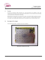
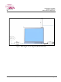
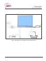
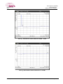
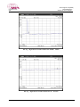
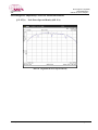
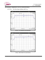
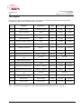
MET Laboratories, Inc.
Safety Certification - EMI - Telecom Environmental Simulation
33439 WESTERN AVENUE ! UNION CITY, CALIFORNIA 94587-3201 ! PHONE (510) 489-6300 ! FAX (510) 489-6372
November 28, 2006
Ubiquiti Networks
495-499 Montague Expressway
Milpitas, CA 95035
Dear Robert Pera,
Enclosed is the Telecom test report for compliance testing of the Ubiquiti Networks, XR2 as tested to the
requirements of Title 47 of the CFR, Ch. 1 (10-1-03 ed.), Part 15, Subpart B for a Class A Digital Device and
Subpart C for Intentional Radiators.
Thank you for using the services of MET Laboratories, Inc. If you have any questions regarding these results or
if MET can be of further service to you, please feel free to contact me.
Sincerely yours,
MET LABORATORIES, INC.
Jennifer Sanchez
Documentation Department
Reference: (\Ubiquiti Networks\EMCS21035B-FCC247)
Certificates and reports shall not be reproduced except in full, without the written permission of MET Laboratories, Inc. While use of the National
Voluntary Laboratory Accreditation Program (NVLAP) letters or the NVLAP Logo, the Standards Council of Canada Logo, or the Nationally
Recognized Testing Laboratory (NRTL) Letters in this report reflects MET Accreditation under these programs, these letters, logo, or statements do not
claim product endorsement by NVLAP or any Agency of the U.S. Government. This letter of transmittal is not a part of the attached report.
The Nation’s First Licensed Nationally Recognized Testing Laboratory
MET Laboratories, Inc.
Safety Certification - EMI - Telecom Environmental Simulation
33439 WESTERN AVENUE ! UNION CITY, CALIFORNIA 94587-3201 ! PHONE (510) 489-6300 ! FAX (510) 489-6372
Electromagnetic Compatibility Criteria
Test Report
For the
Ubiquiti Networks
Model XR2
Verified under
The FCC Certification Rules
Contained in
Title 47 of the CFR, Part 15.247, Subpart C
for Intentional Radiators
MET Report: EMC21035B-FCC247
November 28, 2006
Prepared For:
Ubiquiti Networks
495-499 Montague Expressway
Milpitas, CA 95035
Prepared By:
MET Laboratories, Inc.
4855 Patrick Henry Dr., Building 6
Santa Clara, CA 95054
MET Report: EMCS21035B-FCC247
© 2007, MET Laboratories, Inc.
Page ii of vii
Electromagnetic Compatibility
Cover Page
CFR Title 47, Part 15, Subpart B & C
Ubiquiti Networks
XR2
Electromagnetic Compatibility Criteria
Test Report
For the
Ubiquiti Networks
Model XR2
Tested Under
The FCC Certification Rules
Contained in
Title 47 of the CFR, Part 15.247, Subpart C
For Intentional Radiators
Shawn McMillen, Billy Kwan, Project Engineer
Electromagnetic Compatibility Lab
Jennifer Sanchez
Documentation Department
Engineering Statement: The measurements shown in this report were made in accordance with the procedures indicated, and the
emissions from this equipment were found to be within the limits applicable. I assume full responsibility for the accuracy and
completeness of these measurements, and for the qualifications of all persons taking them. It is further stated that upon the basis of the
measurements made, the equipment tested is capable of operation in accordance with the requirements of Part 15.247, of the FCC Rules
under normal use and maintenance.
Tony Permsombut, Manager
Electromagnetic Compatibility Lab
MET Report: EMCS21035B-FCC247
© 2007, MET Laboratories, Inc.
Page iii of vii
Electromagnetic Compatibility
Report Status Sheet
CFR Title 47, Part 15, Subpart B & C
Ubiquiti Networks
XR2
Report Status Sheet
Revision
Report Date
Reason for Revision
∅
November 28, 2006
Initial Issue.
MET Report: EMCS21035B-FCC247
© 2007, MET Laboratories, Inc.
Page iv of vii
Electromagnetic Compatibility
Table of Contents
CFR Title 47, Part 15, Subpart B & C
Ubiquiti Networks
XR2
Table of Contents
I.
II.
III.
IV.
V.
VI.
Executive Summary .................................................................................................................................................1
A. Purpose of Test ...................................................................................................................................................2
B. Executive Summary ............................................................................................................................................2
Equipment Configuration .......................................................................................................................................3
A. Overview.............................................................................................................................................................4
B. References...........................................................................................................................................................5
C. Test Site ..............................................................................................................................................................6
D. Description of Test Sample.................................................................................................................................6
E. Equipment Configuration....................................................................................................................................9
F. Support Equipment .............................................................................................................................................9
G. Ports and Cabling Information..........................................................................................................................10
H. Mode of Operation............................................................................................................................................10
I. Method of Monitoring EUT Operation .............................................................................................................10
J. Modifications ....................................................................................................................................................10
Modifications to EUT..................................................................................................................10
a)
b)
Modifications to Test Standard....................................................................................................10
K. Disposition of EUT...........................................................................................................................................10
Electromagnetic Compatibility Criteria for Unintentional Radiators ..............................................................11
§ 15.107(a) Conducted Emissions Limits.............................................................................................................. 12
§ 15.109(a) Radiated Emission Limits .................................................................................................................. 17
§ 15.09(a) Radiated Emissions Limits................................................................................................................... 17
Electromagnetic Compatibility Criteria for Intentional Radiators...................................................................20
§ 15.203 Antenna Requirement ............................................................................................................................. 21
§ 15.207(a) Conducted Emissions Limits.............................................................................................................. 22
§ 15.247(a) 6 dB and 99% Bandwidth................................................................................................................... 23
§ 15.247(b) Peak Power Output and RF Exposure................................................................................................ 27
§ 15.247(d) Spurious Emissions Requirements – Radiated and RF Conducted .................................................... 30
§ 15.207(a) Radiated Emissions Limits................................................................................................................. 31
§ 15.247(e) Peak Power Spectral Density ............................................................................................................. 48
Test Equipment ......................................................................................................................................................54
Certification & User’s Manual Information........................................................................................................56
A. Certification Information ..................................................................................................................................57
B. Label and User’s Manual Information ..............................................................................................................61
MET Report: EMCS21035B-FCC247
© 2007, MET Laboratories, Inc.
Page v of vii
Electromagnetic Compatibility
Table of Contents
CFR Title 47, Part 15, Subpart B & C
Ubiquiti Networks
XR2
List of Tables
Table 1 Executive Summary of EMC Part 15.247 ComplianceTesting ................................................................................ 2
Table 2. Equipment Configuration ......................................................................................................................................... 9
Table 3. Support Equipment................................................................................................................................................... 9
Table 4. Ports and Cabling Information ............................................................................................................................... 10
Table 5. Conducted Limits for Radio Frequency Devices calculated from FCC Part 15 Section 15.107(a) (b) .................. 12
Table 6. Conducted Emissions - Voltage, AC Power, Phase Line (110 VAC, 60 Hz)......................................................... 13
Table 7. Conducted Emissions - Voltage, AC Power, Neutral Line (110 VAC, 60 Hz) ...................................................... 13
Table 8. Radiated Emissions Limits calculated from FCC Part 15, §15.109 (a) (b) ............................................................ 17
Table 9. Radiated Emissions Limits Test Results, 30 MHz – 1 GHz................................................................................... 18
Table 10. Conducted Limits for Intentional Radiators from FCC Part 15 § 15.207(a) ........................................................ 22
Table 11. Output Power Requirements from §15.247.......................................................................................................... 27
Table 12. Restricted Bands of Operation.............................................................................................................................. 30
Table 13. Radiated Emissions Limits Calculated from FCC Part 15, § 15.209 (a) .............................................................. 31
List of Figures
Figure 1. Block Diagram of Test Configuration (Radiated Emissions).................................................................................. 7
Figure 2. Block Diagram of Test Configuration (Conducted Measurement) ......................................................................... 8
List of Photographs
Photograph 1. Ubiquiti Networks XR2 ................................................................................................................................... 6
Photograph 2. Conducted Emissions Test Setup – Front View............................................................................................ 15
Photograph 3. Conducted Emissions Test Setup – Rear View ............................................................................................. 16
Photograph 4. Radiated Emission Test Setup 30 MHz - 1 GHz........................................................................................... 19
MET Report: EMCS21035B-FCC247
© 2007, MET Laboratories, Inc.
Page vi of vii
Electromagnetic Compatibility
List of Terms & Abbreviations
CFR Title 47, Part 15, Subpart B & C
Ubiquiti Networks
XR2
List of Terms and Abbreviations
AC
Alternating Current
ACF
Antenna Correction Factor
Cal
Calibration
d
Measurement Distance
dB
Decibels
dBµA
Decibels above one microamp
dBµV
Decibels above one microvolt
dBµA/m
Decibels above one microamp per meter
dBµV/m
Decibels above one microvolt per meter
DC
Direct Current µ
E
Electric Field
DSL
Digital Subscriber Line
ESD
Electrostatic Discharge
EUT
Equipment Under Test
f
Frequency
FCC
Federal Communications Commission
GRP
Ground Reference Plane
H
Magnetic Field
HCP
Horizontal Coupling Plane
Hz
Hertz
IEC
International Electrotechnical Commission
kHz
kilohertz
kPa
kilopascal
kV
kilovolt
LISN
Line Impedance Stabilization Network
MHz
Megahertz
µH
microhenry
µ
microfarad
µs
microseconds
PRF
Pulse Repetition Frequency
RF
Radio Frequency
RMS
Root-Mean-Square
TWT
Traveling Wave Tube
V/m
Volts per meter
VCP
Vertical Coupling Plane
MET Report: EMCS21035B-FCC247
© 2007, MET Laboratories, Inc.
Page vii of vii
Electromagnetic Compatibility
Executive Summary
CFR Title 47, Part 15, Subpart B &C
Ubiquiti Networks
XR2
I.
Executive Summary
MET Report: EMCS21035B-FCC247
© 2007, MET Laboratories, Inc.
Page 1 of 63
Electromagnetic Compatibility
Executive Summary
CFR Title 47, Part 15, Subpart B &C
Ubiquiti Networks
XR2
A.
Purpose of Test
An EMC evaluation was performed to determine compliance of the Ubiquiti Networks XR2, with the
requirements of Part 15, §15.247. All references are to the most current version of Title 47 of the Code of Federal
Regulations in effect. In accordance with §2.1033, the following data is presented in support of the Certification
of the XR2. Ubiquiti Networks should retain a copy of this document which should be kept on file for at least
two years after the manufacturing of the XR2, has been permanently discontinued
B.
Executive Summary
The following tests were conducted on a sample of the equipment for the purpose of demonstrating compliance
with Part 15, §15.247, in accordance with Ubiquiti Networks, purchase order number 610004. All tests were
conducted using measurement procedure ANSI C63.4-2003.
RSS-210 and
RSS-GEN
Description
Results
§15.207
6.6
AC Power Line Conducted Emissions
Compliant
§15.203/15.247(c)
A8.4
Antenna Requirement
Compliant
§15.247(a)(3)
A8.2
6dB Occupied Bandwidth
Compliant
§15.247(b)(3)
A8.4
Maximum Peak Conducted Output Power
Compliant
§15.247(d), §15.205, §15.209
A8.5
Spurious Radiated and Conducted Emissions
Compliant
§15.247(e)
A8.2/RSS-102
Peak Power Spectral Density and RF Exposure
Compliant
15.107
7.4
AC Power Line Conducted Emissions
Compliant
15.109
7.3
Radiated Spurious Emissions
Compliant
FCC Reference
Transmitter Mode (TX)
Receiver Mode (RX)
Table 1 Executive Summary of EMC Part 15.247 ComplianceTesting
MET Report: EMCS21035B-FCC247
© 2007, MET Laboratories, Inc.
Page 2 of 63
Electromagnetic Compatibility
Equipment Configuration
CFR Title 47, Part 15, Subpart B &C
Ubiquiti Networks
XR2
II.
Equipment Configuration
MET Report: EMCS21035B-FCC247
© 2007, MET Laboratories, Inc.
Page 3 of 63
Electromagnetic Compatibility
Equipment Configuration
CFR Title 47, Part 15, Subpart B &C
Ubiquiti Networks
XR2
A.
Overview
MET Laboratories, Inc. was contracted by Ubiquiti Networks to perform testing on the XR2, under Ubiquiti
Networks’s purchase order number 610004.
This document describes the test setups, test methods, required test equipment, and the test limit criteria used to
perform compliance testing of the Ubiquiti Networks, XR2.
The results obtained relate only to the item(s) tested.
Model(s) Tested:
XR2
Model(s) Covered:
XR2
Primary Power: 110 V AC, 60 Hz
FCC ID: SWX-XR2
EUT
Specifications:
Analysis:
Type of Modulations:
-Direct Sequence Spread Spectrum(DSSS)
-Orthogonal Frequency Division Multiplexing(OFDM)
Emission Designators:
D7D
Equipment Code:
DTS
Peak RF Output Power:
802.11/b Mode: 29.90dBm
EUT Frequency Ranges:
2412 – 2462MHz
802.11/g Mode: 28.06dBm
The results obtained relate only to the item(s) tested.
Temperature (15-35º C)
Environmental
Test Conditions:
Relative Humidity (30-60%)
Barometric Pressure (860-1060 mbar)
Evaluated by:
Report Date:
MET Report: EMCS21035B-FCC247
Shawn McMillen, Billy Kwan
November 28, 2006
© 2007, MET Laboratories, Inc.
Page 4 of 63
Electromagnetic Compatibility
Equipment Configuration
CFR Title 47, Part 15, Subpart B &C
Ubiquiti Networks
XR2
B.
References
CFR 47, Part 15, Subpart C
Federal Communication Commission, Code of Federal Regulations, Title 47,
Part 15: General Rules and Regulations, Allocation, Assignment, and Use of
Radio Frequencies
CFR 47, Part 15, Subpart B
Electromagnetic Compatibility: Criteria for Radio Frequency Devices
ANSI C63.4:2003
Methods and Measurements of Radio-Noise Emissions from Low-Voltage
Electrical And Electronic Equipment in the Range of 9 kHz to 40 GHz
ANSI/NCSL Z540-1-1994
Calibration Laboratories and Measuring and Test Equipment - General
Requirements
ANSI/ISO/IEC 17025:2000
General Requirements for the Competence of Testing and Calibration
Laboratories
MET Report: EMCS21035B-FCC247
© 2007, MET Laboratories, Inc.
Page 5 of 63
Electromagnetic Compatibility
Equipment Configuration
CFR Title 47, Part 15, Subpart B &C
Ubiquiti Networks
XR2
C.
Test Site
All testing was performed at MET Laboratories, Inc., 4855 Patrick Henry Drive, Building 6, Santa Clara,
California 95054. All equipment used in making physical determinations is accurate and bears recent traceability
to the National Institute of Standards and Technology.
Radiated Emissions measurements were performed in a 10 meter semi-anechoic chamber (equivalent to an Open
Area Test Site). In accordance with §2.948(a)(3), a complete site description is contained at MET Laboratories.
In accordance with §2.948(d), MET Laboratories has been accredited by A2LA (Certificate Number 591.02).
D.
Description of Test Sample
The Ubiquiti Networks XR2, is a modular wireless device (PCMCIA).
Photograph 1. Ubiquiti Networks XR2
MET Report: EMCS21035B-FCC247
© 2007, MET Laboratories, Inc.
Page 6 of 63
Electromagnetic Compatibility
Equipment Configuration
CFR Title 47, Part 15, Subpart B &C
Ubiquiti Networks
XR2
Figure 1. Block Diagram of Test Configuration (Radiated Emissions)
MET Report: EMCS21035B-FCC247
© 2007, MET Laboratories, Inc.
Page 7 of 63
Electromagnetic Compatibility
Equipment Configuration
CFR Title 47, Part 15, Subpart B &C
Ubiquiti Networks
XR2
Figure 2. Block Diagram of Test Configuration (Conducted Measurement)
MET Report: EMCS21035B-FCC247
© 2007, MET Laboratories, Inc.
Page 8 of 63
Electromagnetic Compatibility
Equipment Configuration
CFR Title 47, Part 15, Subpart B &C
Ubiquiti Networks
XR2
E.
Equipment Configuration
The EUT was set up as outlined in Figure 1, Block Diagram of Test Setup. All cards, racks, etc., incorporated as
part of the EUT is included in the following list.
Ref. ID
Name / Description
Model Number
Serial Number
A
E
XR2 802.11b/g w/ 0dBi antenna
Antenna (Ubiquiti Networks)
XR2C
SR4-ANT
Proto 1
N/A
Table 2. Equipment Configuration
F.
Support Equipment
Ubiquiti Networks supplied support equipment necessary for the operation and testing of the XR2. All support
equipment supplied is listed in the following Support Equipment List.
Ref. ID
Name / Description
Manufacturer
Model Number
B
C
D
F
G
H
PCMCIA Extension Card
Laptop
AC-DC PWR Adaptor
Spectrum Analyzer
50ohms terminator
Printer
Accurite Technologies
Dell
Dell
HP
N/A
HP
307507
Latitude
PA-2
E4407B
N/A
DeskJet 932C
Table 3. Support Equipment
MET Report: EMCS21035B-FCC247
© 2007, MET Laboratories, Inc.
Page 9 of 63
Electromagnetic Compatibility
Equipment Configuration
CFR Title 47, Part 15, Subpart B &C
Ubiquiti Networks
XR2
G.
Ports and Cabling Information
Ref. ID
Port name on EUT
1
2
3
A, Antenna
C, PWR
D, AC Input
1
2
3
A, Antenna
C, PWR
D, AC Input
1
2
3
4
C, PWR
D, AC Input
C, Printer
C,USB
Cable Description or reason
Length
Qty.
for no cable
(m)
Conducted Measurement
Coax
1
1.5
DC Power Cord
1
1.5
AC Cable
1
1.5
Spurious Emission
Coax
1
0.5
DC Power Cord
1
1.5
AC Cable
1
1.5
15.107 & 15.109
DC Power Cord
1
1.5
AC Cable
1
1.5
DB25
1
2
USB
1
2
Shielded?
Termination Box ID &
Port ID
Yes
No
No
F, Input
D, DC Output
AC PWR Outlet
Yes
No
No
E, Antenna
D, DC Output
AC PWR Outlet
No
No
Yes
Yes
D, DC Output
AC PWR Outlet
H
I
Table 4. Ports and Cabling Information
H.
Mode of Operation
- Direct Sequence Spread Spectrum(DSSS)
- Orthogonal Frequency Division Multiplexing(OFDM)
I.
Method of Monitoring EUT Operation
A Laptop with Atheros radio test software was used to monitor the EUT’s transmitter channel and power output.
J.
Modifications
a)
Modifications to EUT
No modifications were made to the EUT.
b)
Modifications to Test Standard
No modifications were made to the test standard.
K.
Disposition of EUT
The test sample including all support equipment submitted to the Electro-Magnetic Compatibility Lab for testing
was returned to Ubiquiti Networks upon completion of testing.
MET Report: EMCS21035B-FCC247
© 2007, MET Laboratories, Inc.
Page 10 of 63
Electromagnetic Compatibility
Unintentional Radiators
CFR Title 47, Part 15, Subpart B
Ubiquiti Networks
XR2
III. Electromagnetic Compatibility Criteria
for Unintentional Radiators
MET Report: EMCS21035B-FCC247
© 2007, MET Laboratories, Inc.
Page 11 of 63
Electromagnetic Compatibility
Unintentional Radiators
CFR Title 47, Part 15, Subpart B
Ubiquiti Networks
XR2
Electromagnetic Compatibility Criteria for Unintentional Radiators
§ 15.107
Test Requirement(s):
Conducted Emissions Limits
15.107 (a) “Except for Class A digital devices, for equipment that is designed to be connected to
the public utility (AC) power line, the radio frequency voltage that is conducted back onto the
AC power line on any frequency or frequencies within the band 150 kHz to 30 MHz shall not
exceed the limits in Table 5. Compliance with this provision shall be based on the
measurement of the radio frequency voltage between each power line and ground at the power
terminals.”
15.107 (b) “For a Class A digital device that is designed to be connected to the public utility
(AC) power line, the radio frequency voltage that is conducted back onto the AC power line on
any frequency or frequencies within the band 150 kHz to 30 MHz shall not exceed the limits in
Table 5. Compliance with this provision shall be based on the measurement of the radio
frequency voltage between each power line and ground at the power terminals. The lower limit
applies at the band edges.”
Frequency range
(MHz)
15.107(b), Class A Limits
(dBµV)
15.107(a), Class B Limits
(dBµV)
Quasi-Peak
Average
Quasi-Peak
Average
0.15- 0.5
79
66
66 - 56
56 - 46
0.5 – 5.0
73
60
56
46
5.0 - 30
73
60
60
50
Note 1 — The lower limit shall apply at the transition frequencies.
Table 5. Conducted Limits for Radio Frequency Devices calculated from FCC Part 15
Section 15.107(a) (b)
Test Procedures:
The EUT was placed on a 0.8m-high wooden table inside a semi-anechoic chamber. The
method of testing, test conditions, and test procedures of ANSI C63.4 were used. The EUT was
powered through a 50Ω/50µH LISN. An EMI receiver, connected to the measurement port of
the LISN, scanned the frequency range from 150 kHz to 30 MHz in order to find the peak
conducted emissions. All peak emissions within 6 dB of the limit were measured using a quasipeak and/or average detector as appropriate.
Test Results:
The EUT complies with the Class A requirements of this section. Measured emissions were
below applicable limits.
Test Engineer(s):
Billy Kwan
Test Date(s):
October 27, 2006
MET Report: EMCS21035B-FCC247
© 2007, MET Laboratories, Inc.
Page 12 of 63
Electromagnetic Compatibility
Unintentional Radiators
CFR Title 47, Part 15, Subpart B
Ubiquiti Networks
XR2
Conducted Emissions - Voltage, AC Power, Phase Line (110 VAC, 60 Hz)
FREQ.
(MHz)
3.5
5.4
10.64
Corrected
Amplitude
(dBuV)
QP
38.4
39.5
44
Limit
(dBuV)
QP
Results
QP
Margin
(dB) QP
73
73
73
PASS
PASS
PASS
-34.6
-33.5
-29
Corrected
Amplitude
(dBuV)
AVG
33.2
29.4
38.7
Limit
(dBuV)
AVG
Results
AVG
Margin
(dB)
AVG
60
60
60
PASS
PASS
PASS
-26.8
-30.6
-21.3
Limit
(dBuV)
AVG
Results
AVG
Margin
(dB)
AVG
60
60
60
PASS
PASS
PASS
-29.05
-23.442
-22.17
Table 6. Conducted Emissions - Voltage, AC Power, Phase Line (110 VAC, 60 Hz)
Conducted Emissions - Voltage, AC Power, Neutral Line (110 VAC, 60 Hz)
FREQ.
(MHz)
3.483
4.997
10.878
Corrected
Amplitude
(dBuV)
QP
38.43
42.41
43.75
Limit
(dBuV)
QP
Results
QP
Margin
(dB) QP
73
73
73
PASS
PASS
PASS
-34.57
-30.59
-29.25
Corrected
Amplitude
(dBuV)
AVG
30.95
36.558
37.83
Table 7. Conducted Emissions - Voltage, AC Power, Neutral Line (110 VAC, 60 Hz)
MET Report: EMCS21035B-FCC247
© 2007, MET Laboratories, Inc.
Page 13 of 63
Electromagnetic Compatibility
Unintentional Radiators
CFR Title 47, Part 15, Subpart B
Ubiquiti Networks
XR2
Conducted Emissions - Voltage, Worst Case Emissions, AC Power, (110 VAC, 60 Hz)
Conducted Emissions Voltage 150kHz to 30MHz
130
120
110
Amplitude (dBuV/m)
100
90
80
70
60
50
40
30
20
10
0
-10
0.1
1
10
100
Frequency (MHz)
Conducted Emission, Phase Line Plot
Conducted Emissions Voltage 150kHz to 30MHz
130
120
110
Amplitude (dBuV/m)
100
90
80
70
60
50
40
30
20
10
0
-10
0.1
1
10
100
Frequency (MHz)
Conducted Emission, Neutral Line Plot
MET Report: EMCS21035B-FCC247
© 2007, MET Laboratories, Inc.
Page 14 of 63
Electromagnetic Compatibility
Unintentional Radiators
CFR Title 47, Part 15, Subpart B
Ubiquiti Networks
XR2
Conducted Emission Limits Test Setup
Photograph 2. Conducted Emissions Test Setup – Front View
MET Report: EMCS21035B-FCC247
© 2007, MET Laboratories, Inc.
Page 15 of 63
Electromagnetic Compatibility
Unintentional Radiators
CFR Title 47, Part 15, Subpart B
Ubiquiti Networks
XR2
Conducted Emission Limits Test Setup
Photograph 3. Conducted Emissions Test Setup – Rear View
MET Report: EMCS21035B-FCC247
© 2007, MET Laboratories, Inc.
Page 16 of 63
Electromagnetic Compatibility
Unintentional Radiators
CFR Title 47, Part 15, Subpart B
Ubiquiti Networks
XR2
Radiated Emission Limits
§ 15.109
Test Requirement(s):
Radiated Emissions Limits
15.109 (a) Except for Class A digital devices, the field strength of radiated emissions from
unintentional radiators at a distance of 3 meters shall not exceed the Class B limits expressed in
Table 8.
15.109 (b) The field strength of radiated emissions from a Class A digital device, as determined
at a distance of 10 meters, shall not exceed the Class A limits expressed in Table 8.
Field Strength (dBµV/m)
Frequency (MHz)
§15.109 (b), Class A Limit
(dBµV) @ 10m
§15.109 (a),Class B Limit
(dBµV) @ 3m
30 - 88
88 - 216
216 - 960
Above 960
39.00
43.50
46.40
49.50
40.00
43.50
46.00
54.00
Table 8. Radiated Emissions Limits calculated from FCC Part 15, §15.109 (a) (b)
Test Procedures:
The EUT was placed on a 0.8m-high wooden table inside a semi-anechoic chamber. The
method of testing and test conditions of ANSI C63.4 were used. An antenna was located 10 m
from the EUT on an adjustable mast. A pre-scan was first performed in order to find prominent
radiated emissions. For final emissions measurements at each frequency of interest, the EUT
was rotated and the antenna height was varied between 1 m and 4 m in order to maximize the
emission. Measurements in both horizontal and vertical polarities were made and the data was
recorded. Unless otherwise specified, measurements were made using a quasi-peak detector
with a 120 kHz bandwidth.
Test Results:
The EUT was found Compliant with the Class A requirement(s) of this section. Measured
emissions were below applicable limits
Test Engineer(s):
Billy Kwan
Test Date(s):
October 27, 2006
MET Report: EMCS21035B-FCC247
© 2007, MET Laboratories, Inc.
Page 17 of 63
Electromagnetic Compatibility
Unintentional Radiators
CFR Title 47, Part 15, Subpart B
Ubiquiti Networks
XR2
Radiated Emissions Limits Test Results, Class A
Frequency
(MHz)
Antenna
Polarity
(H/V)
EUT
Azimuth
(Degrees)
Antenna
HEIGHT
(m)
99.6
266.56
298.76
336.64
366.52
431.52
H
H
H
H
H
H
11
223
230
159
206
317
321
3.46
3.09
1.83
2.69
2.01
Uncorrected
Amplitude
QP Detector
(dBuv)
27.79
24.47
21.74
22.31
15.27
10.37
Antenna
Correction
Factor
(dB/m) (+)
10.24
13.21
12.81
14.07
14.70
16.90
Cable
Loss
(dB) (+)
Corrected
Amplitude
(dBuV/m)
Limit
(dBuV/m)
Margin
(dB)
1.73
2.70
2.92
3.13
3.30
3.66
39.77
40.38
37.47
39.50
33.27
30.93
43.50
46.40
46.40
46.40
46.40
46.40
-3.73
-6.02
-8.93
-6.90
-13.13
-15.47
Table 9. Radiated Emissions Limits Test Results, 30 MHz – 1 GHz
Radiated Emissions Limits Test Results, 30 MHz – 1 GHz, Class A
MET Report: EMCS21035B-FCC247
© 2007, MET Laboratories, Inc.
Page 18 of 63
Electromagnetic Compatibility
Unintentional Radiators
CFR Title 47, Part 15, Subpart B
Ubiquiti Networks
XR2
Radiated Emission Limits Test Setup
Photograph 4. Radiated Emission Test Setup 30 MHz - 1 GHz
MET Report: EMCS21035B-FCC247
© 2007, MET Laboratories, Inc.
Page 19 of 63
Electromagnetic Compatibility
Intentional Radiators
CFR Title 47, Part 15, Subpart C
Ubiquiti Networks
XR2
IV. Electromagnetic Compatibility Criteria
for Intentional Radiators
MET Report: EMCS21035B-FCC247
© 2007, MET Laboratories, Inc.
Page 20 of 63
Electromagnetic Compatibility
Intentional Radiators
CFR Title 47, Part 15, Subpart C
Ubiquiti Networks
XR2
Electromagnetic Compatibility Criteria for Intentional Radiators
§ 15.203
Test Requirement:
Antenna Requirement
§ 15.203: An intentional radiator shall be designed to ensure that no antenna other than that
furnished by the responsible party shall be used with the device. The use of a permanently
attached antenna or of an antenna that uses a unique coupling to the intentional radiator shall be
considered sufficient to comply with the provisions of this section. The manufacturer may
design the unit so that a broken antenna can be replaced by the user, but the use of a standard
antenna jack or electrical connector is prohibited.
The structure and application of the EUT were analyzed to determine compliance with Section
15.203 of the Rules. Section 15.203 states that the subject device must meet at least one of the
following criteria:
a.) Antenna must be permanently attached to the unit.
b.) Antenna must use a unique type of connector to attach to the EUT.
c.) Unit must be professionally installed. Installer shall be responsible for verifying
that the correct antenna is employed with the unit.
Results:
The EUT as tested meets the criteria of this rule by virtue of having professionally installed.
The EUT is therefore compliant with §15.203.
Manufacturer
Hyperliniktech
Test Engineer(s):
Shawn McMillen
Test Date(s):
October 27, 2006
MET Report: EMCS21035B-FCC247
Type
Dipole
Model
HG2403RD-RSF
© 2007, MET Laboratories, Inc.
Gain
3dBi
Page 21 of 63
Electromagnetic Compatibility
Intentional Radiators
CFR Title 47, Part 15, Subpart C
Ubiquiti Networks
XR2
Electromagnetic Compatibility Criteria for Intentional Radiators
§ 15.207
Test Requirement(s):
Conducted Emissions Limits
§ 15.207 (a): For an intentional radiator that is designed to be connected to the public utility
(AC) power line, the radio frequency voltage that is conducted back onto the AC power line on
any frequency or frequencies, within the band 150 kHz to 30MHz, shall not exceed the limits in
the following table, as measured using a 50 µH/50 Σ line impedance stabilization network
(LISN). Compliance with the provisions of this paragraph shall be based on the measurement of
the radio frequency voltage between each power line and ground at the power terminal. The
lower limit applies at the boundary between the frequency ranges.
Frequency range
(MHz)
§ 15.207(a), Conducted Limit (dBµV)
Quasi-Peak
Average
* 0.15- 0.45
66 - 56
56 - 46
0.45 - 0.5
56
46
0.5 - 30
60
50
Table 10. Conducted Limits for Intentional Radiators from FCC Part 15 § 15.207(a)
Test Procedure:
The EUT was placed on a 0.8 m-high wooden table inside a semi-anechoic chamber. The EUT
was situated such that the back of the EUT was 0.4 m from one wall of the vertical ground
plane, and the remaining sides of the EUT were no closer than 0.8 m from any other conductive
surface. The EUT was powered from a 50 Ω/50 µH Line Impedance Stabilization Network
(LISN). The EMC receiver scanned the frequency range from 150 kHz to 30 MHz. Conducted
Emissions measurements were made in accordance with ANSI C63.4-1992 "Methods and
Measurements of Radio-Noise Emissions from Low-Voltage Electrical and Electronic
Equipment in the Range of 9kHz to 40 GHz". The measurements were performed over the
frequency range of 0.15 MHz to 30 MHz using a 50 Ω/50 µH LISN as the input transducer to an
EMC/field intensity meter. The tests were conducted in a RF-shielded enclosure.
Test Results:
The EUT complies with the requirements of this section.
Test Engineer(s):
Billy Kwan
Test Date(s):
October 27, 2006
MET Report: EMCS21035B-FCC247
© 2007, MET Laboratories, Inc.
Page 22 of 63
Electromagnetic Compatibility
Intentional Radiators
CFR Title 47, Part 15, Subpart C
Ubiquiti Networks
XR2
Electromagnetic Compatibility Criteria for Intentional Radiators
§ 15.247(a)
Test Requirements:
6 dB and 99% Bandwidth
§ 15.247(a): Operation under the provisions of this section is limited to frequency hopping and
digitally modulated intentional radiators that comply with the following provisions:
For systems using digital modulation techniques, the EUT may operate in the 902-928 MHz,
2400-2483.5 MHz and 5725-5850 MHz bands. The minimum 6dB bandwidth shall be at least
500 kHz.
Test Procedure:
The transmitter was set to the mid channel at the highest output power and connected to the
spectrum analyzer through an attenuator. The bandwidth of the fundamental frequency was
measured with the spectrum analyzer using a RBW approximately equal to 1% of the total
emission bandwidth, VBW > RBW. The 6 dB Bandwidth was measured and recorded. The
measurements were repeated at the low and high channels.
Test Results
Equipment complies with § 15.247 (a). The 6 dB and 99% Bandwidth was determined from the
plots on the following pages.
Test Engineer(s):
Shawn McMillen,
Test Date(s):
October 27, 2006
EUT
Attenuator
Spectrum
Analyzer
Block Diagram 1. Occupied Bandwidth Test Setup
MET Report: EMCS21035B-FCC247
© 2007, MET Laboratories, Inc.
Page 23 of 63
Electromagnetic Compatibility
Intentional Radiators
CFR Title 47, Part 15, Subpart C
Ubiquiti Networks
XR2
Electromagnetic Compatibility Criteria for Intentional Radiators
802.11/b Low Ch Occupied Band Width.
802.11/b Mid Ch Occupied Band Width
MET Report: EMCS21035B-FCC247
© 2007, MET Laboratories, Inc.
Page 24 of 63
Electromagnetic Compatibility
Intentional Radiators
CFR Title 47, Part 15, Subpart C
Ubiquiti Networks
XR2
802.11/b High Ch Occupied Band Width
802.11/g Low Ch Occupied Band Width
MET Report: EMCS21035B-FCC247
© 2007, MET Laboratories, Inc.
Page 25 of 63
Electromagnetic Compatibility
Intentional Radiators
CFR Title 47, Part 15, Subpart C
Ubiquiti Networks
XR2
802.11/g Mid Ch Occupied Band Width
802.11/g High Ch Occupied Band Width
MET Report: EMCS21035B-FCC247
© 2007, MET Laboratories, Inc.
Page 26 of 63
Electromagnetic Compatibility
Intentional Radiators
CFR Title 47, Part 15, Subpart C
Ubiquiti Networks
XR2
Electromagnetic Compatibility Criteria for Intentional Radiators
§ 15.247(b)
Test Requirements:
Peak Power Output and RF Exposure
§15.247(b): The maximum peak output power of the intentional radiator shall not exceed the
following:
Digital Transmission Systems
(MHz)
Output Limit
(Watts)
902-928
2400–2483.5
5725– 5850
1.000
1.000
1.000
Table 11. Output Power Requirements from §15.247
§15.247(c): if transmitting antennas of directional gain greater than 6 dBi are used the peak
output power from the intentional radiator shall be reduced below the stated values in the Table
11, as appropriate, by the amount in dB that the directional gain of the antenna exceeds 6 dBi.
Systems operating in the 2400 – 2483.5 MHz band may employ transmitting antennas with
directional gain greater than 6 dBi provided the maximum peak output power of the intentional
radiator is reduced by 1 dB for every 3 dB that the directional gain of the antenna exceeds 6 dBi.
Systems operating in the 5725 – 5850 MHz band that are used exclusively for fixed, point-topoint operations may employ transmitting antennas with directional gain greater than 6 dBi
without any corresponding reduction in transmitter peak output power.
Fixed, point-to-point operation excludes the use of point-to-multipoint systems, omnidirectional applications, and multiple co-located intentional radiators transmitting the same
information. The operator of the spread spectrum intentional radiator or, if the equipment is
professionally installed, the installer is responsible for ensuring that the system is used
exclusively for fixed, point-to-point operations. The instruction manual furnished with the
intentional radiator shall contain language in the installation instructions informing the operator
and the installer of this responsibility.
Test Procedure:
The transmitter was connected to a calibrated Peak Power Meter. The EUT was measured at the
low, mid and high channels of each band at a data rate which gave the maximum power level.
MET Report: EMCS21035B-FCC247
© 2007, MET Laboratories, Inc.
Page 27 of 63
Electromagnetic Compatibility
Intentional Radiators
CFR Title 47, Part 15, Subpart C
Ubiquiti Networks
XR2
Test Results:
Equipment complies with the Peak Power Output limits of § 15.247(b).
Carrier Channel
Low
Mid
High
Carrier Channel
Low
Mid
High
Test Engineer(s):
Shawn McMillen
Test Date(s):
10/27/06
EUT
802.11b mode
Frequency
Measured Peak Output Power
(MHz)
dBm
2412
29.34
2437
29.90
2462
29.65
802.11g mode
Frequency
Measured Peak Output Power
(MHz)
dBm
2412
28.06
2437
27.93
2462
28.01
Attenuator
Power
Meter
Block Diagram 2. Peak Power Output Test Setup
MET Report: EMCS21035B-FCC247
© 2007, MET Laboratories, Inc.
Page 28 of 63
Electromagnetic Compatibility
Intentional Radiators
CFR Title 47, Part 15, Subpart C
Ubiquiti Networks
XR2
Electromagnetic Compatibility Criteria for Intentional Radiators
§ 15.247(b)
Peak Power Output and RF Exposure
RF Exposure Requirements:
§1.1307(b)(1) and §1.1307(b)(2): Systems operating under the provisions of this
section shall be operated in a manner that ensures that the public is not exposed to
radio frequency energy levels in excess of the Commission’s guidelines.
RF Radiation Exposure Limit:
§1.1310: As specified in this section, the Maximum Permissible Exposure (MPE)
Limit shall be used to evaluate the environmental impact of human exposure to
radiofrequency (RF) radiation as specified in Sec. 1.1307(b), except in the case of
portable devices which shall be evaluated according to the provisions of Sec. 2.1093 of
this chapter.
MPE Limit Calculation: EUT’s operating frequencies @ 2400-2483.5 MHz; highest conducted power =
29.90dBm (peak) therefore, Limit for Uncontrolled exposure: 1 mW/cm2 or 10 W/m2
EUT maximum antenna gain = 3 dBi.
Power Density Determination:
S = PG / 4πR2
or
R = √(PG / 4πS)
where, S = Power Density (1 mW/cm2)
P = Linear Power Input to antenna (977.2)
G = Numerical Antenna Gain (2.0)
R = Radius (20cm)
S = (977.2*2.0/4π202) = (1954.2/5024) = 0.39 mW/cm2 @ 20cm
MET Report: EMCS21035B-FCC247
© 2007, MET Laboratories, Inc.
Page 29 of 63
Electromagnetic Compatibility
Intentional Radiators
CFR Title 47, Part 15, Subpart C
Ubiquiti Networks
XR2
Electromagnetic Compatibility Criteria for Intentional Radiators
§ 15.247(d)
Test Requirements:
Harmonic Emissions – Radiated and Conducted
§15.247(d); Error! Reference source not found.; §15.205: Emissions outside the frequency
band.
§15.247(d): In any 100 kHz bandwidth outside the frequency band in which the spread
spectrum or digitally modulated intentional radiator is operating, the radio frequency power that
is produced by the intentional radiator shall be at least 20 dB below that in the 100 kHz
bandwidth within the band that contains the highest level of the desired power, based on either
an RF conducted or a radiated measurement. Attenuation below the general limits specified in §
15.209(a) is not required. In addition, radiated emissions which fall in the restricted bands, as
defined in § 15.205(a), must also comply with the radiated emission limits specified in §
15.209(a).
§15.205(a): Except as shown in paragraph (d) of this section, only spurious emissions are
permitted in any of the frequency bands listed below:
MHz
MHz
MHz
GHz
0.090–0.110---------------------
16.42–16.423
399.9–410
4.5–5.15
1
0.495–0.505------------------
16.69475–16.69525
608–614
5.35–5.46
2.1735–2.1905------------------
16.80425–16.80475
960–1240
7.25–7.75
4.125–4.128---------------------
25.5–25.67
1300–1427
8.025–8.5
4.17725–4.17775---------------
37.5–38.25
1435–1626.5
9.0–9.2
4.20725–4.20775---------------
73–74.6
1645.5–1646.5
9.3–9.5
6.215–6.218---------------------
74.8–75.2
1660–1710
10.6–12.7
6.26775–6.26825---------------
108–121.94
1718.8–1722.2
13.25–13.4
6.31175–6.31225---------------
123–138
2200–2300
14.47–14.5
8.291–8.294---------------------
149.9–150.05
2310–2390
15.35–16.2
8.362–8.366---------------------
156.52475–156.52525
2483.5–2500
17.7–21.4
8.37625–8.38675---------------
156.7–156.9
2655–2900
22.01–23.12
8.41425–8.41475---------------
162.0125–167.17
3260–3267
23.6–24.0
12.29–12.293-------------------
167.72–173.2
3332–3339
31.2–31.8
12.51975–12.52025------------
240–285
3345.8–3358 36.
43–36.5
12.57675–12.57725------------
322–335.4
3600–4400
(
2
)
Table 12. Restricted Bands of Operation
1
2
Until February 1, 1999, this restricted band shall be 0.490 – 0.510 MHz.
Above 38.6
MET Report: EMCS21035B-FCC247
© 2007, MET Laboratories, Inc.
Page 30 of 63
Electromagnetic Compatibility
Intentional Radiators
CFR Title 47, Part 15, Subpart C
Ubiquiti Networks
XR2
§ 15.209
Test Requirement(s):
Radiated Emissions Limits
§ 15.209 (a): Except as provided elsewhere in this subpart, the emissions from an intentional
radiator shall not exceed the field strength levels specified in Error! Reference source not
found..
Frequency (MHz)
30 - 88
88 - 216
216 - 960
Above 960
§ 15.209(a),Radiated Emission Limits
(dBµV) @ 3m
40.00
43.50
46.00
54.00
Table 13. Radiated Emissions Limits Calculated from FCC Part 15, § 15.209 (a)
Test Procedure:
The transmitter was set to the mid channel at the highest output power and placed on a 0.8 m
high wooden table inside in a semi-anechoic chamber. Measurements were performed with the
EUT rotated 360 degrees and varying the adjustable antenna mast with 1 m to 4 m height to
determine worst case orientation for maximum emissions. Measurement were repeated the
measurement at the low and highest channels.
For frequencies from 30 MHz to 1 GHz, measurements were made using a quasi-peak detector
with a 120 kHz bandwidth.
For intentional radiators with a digital device portion which operates below 10 GHz, the
spectrum was investigated as per §15.33(a)(1) and §15.33(a)(4); i.e., the lowest RF signal
generated or used in the device up to the 10th harmonic of the highest fundamental frequency or
to 40 GHz, whichever is lower.
In accordance with §15.35(b) the limit on the radio frequency emissions as measured using
instrumentation with a peak detector function shall be 20 dB above the maximum permitted
average limit for the frequency being investigated unless a different peak emission limit is
otherwise specified in the rules.
EUT Field Strength Final Amplitude = Raw Amplitude – Preamp gain + Antenna Factor +
Cable Loss – Distance Correction Factor (1 meter)
Test Results:
The EUT was found compliant with the Radiated Emission limits of §15.209(a) for Intentional
Radiators. See following pages for detailed test results.
Test Engineer(s):
Shawn McMillen, Billy Kwan
Test Date(s):
October 27, 2006
MET Report: EMCS21035B-FCC247
© 2007, MET Laboratories, Inc.
Page 31 of 63
Electromagnetic Compatibility
Intentional Radiators
CFR Title 47, Part 15, Subpart C
Ubiquiti Networks
XR2
Electromagnetic Compatibility Criteria for Intentional Radiators
§ 15.247(d)
Frequency
(MHz)
Receive
Antenna
Polarity
(H/V)
4824
4824
7236
7236
9648
V
V
V
V
V
Harmonic Emissions Requirements – Radiated (802.11b)
Uncorrected
Preamp
Field strength
(dB)
(dBµV)@ 3m
43.5
33.2
34.7
30.2
34.5
35.1
35.1
35.1
35.1
35.6
Antenna
Factor
(dB)
33.5
33.5
37.0
37.0
38.5
Corrected
Cable Field Strength
Loss (dB)
@ 3m
(dBµV)
5.2
5.2
6.5
6.5
7.8
47.1
36.8
43.1
38.6
45.2
Limit
@ 3m
(dBµV)
Margin
(dB)
Measurement
Type
74.0
54.0
74.0
54.0
74.0
26.9
17.2
30.9
15.4
28.8
pk
avg
pk
avg
pk
Limit
@ 3m
(dBµV)
Margin
(dB)
Measurement
Type
74.0
54.0
74.0
54.0
74.0
26.3
16.1
22.9
15.0
19.3
pk
avg
pk
avg
pk
Limit
@ 3m
(dBµV)
Margin
(dB)
Measurement
Type
Low Channel 2414MHz
Frequency
(MHz)
Receive
Antenna
Polarity
(H/V)
4874
4874
7311
7311
9748
V
V
V
V
V
Uncorrected
Preamp
Field strength
(dB)
(dBµV)@ 3m
44.1
34.3
42.7
30.6
44.0
35.1
35.1
35.1
35.1
35.6
Antenna
Factor
(dB)
33.5
33.5
37.0
37.0
38.5
Corrected
Cable Field Strength
Loss (dB)
@ 3m
(dBµV)
5.2
5.2
6.5
6.5
7.8
47.7
37.9
51.1
39.0
54.7
Mid Channel 2445
Corrected
Cable Field Strength
@ 3m
Loss (dB)
(dBµV)
Frequency
(MHz)
Receive
Antenna
Polarity
(H/V)
4924
V
42.9
35.1
33.5
5.2
46.5
74.0
27.5
pk
4924
7386
7386
9848
V
V
V
V
30.6
40.9
30.4
44.6
35.1
35.1
35.1
35.6
33.5
37.0
37.0
38.5
5.2
6.5
6.5
7.8
34.2
49.3
38.8
55.3
54.0
74.0
54.0
74.0
19.8
24.7
15.2
18.7
avg
pk
avg
pk
Uncorrected
Preamp
Field strength
(dB)
(dBµV)@ 3m
Antenna
Factor
(dB)
High Channel 2460MHz
Note: All other emissions were measured at the noise floor of the spectrum analyzer
MET Report: EMCS21035B-FCC247
© 2007, MET Laboratories, Inc.
Page 32 of 63
Electromagnetic Compatibility
Intentional Radiators
CFR Title 47, Part 15, Subpart C
Ubiquiti Networks
XR2
802.11/b radiated restricted band, Low Band Edge-Average
802.11/b radiated restricted band, Low Band Edge- Peak
MET Report: EMCS21035B-FCC247
© 2007, MET Laboratories, Inc.
Page 33 of 63
Electromagnetic Compatibility
Intentional Radiators
CFR Title 47, Part 15, Subpart C
Ubiquiti Networks
XR2
802.11/b radiated restricted band, High Band Edge- Average
802.11/b radiated restricted band, High Band Edge- Peak
MET Report: EMCS21035B-FCC247
© 2007, MET Laboratories, Inc.
Page 34 of 63
Electromagnetic Compatibility
Intentional Radiators
CFR Title 47, Part 15, Subpart C
Ubiquiti Networks
XR2
Electromagnetic Compatibility Criteria for Intentional Radiators
§ 15.247(d)
Frequenc
y
(MHz)
4824
4824
7236
7236
9648
Harmonic Emissions Requirements – Radiated (802.11g)
Receive Uncorrected
Antenna
Field
Preamp
Polarity
strength
(dB)
(H/V) (dBµV)@ 3m
V
V
V
V
V
43.5
30.4
44.1
30.2
41.5
35.1
35.1
35.1
35.1
35.6
Antenna
Factor
(dB)
Cable
Loss (dB)
Corrected
Field
Strength
@ 3m
(dBµV)
33.5
33.5
37.0
37.0
38.5
5.2
5.2
6.5
6.5
7.8
47.1
34.0
52.5
38.6
52.2
Limit
Margin Measurement
@ 3m
(dB)
Type
(dBµV)
74.0
54.0
74.0
54.0
74.0
26.9
20.0
21.5
15.4
21.8
pk
avg
pk
avg
pk
Low Channel 2414MHz
Frequency
(MHz)
4874
4874
7311
7311
9748
Receive Uncorrected
Antenna
Field
Preamp
(dB)
Polarity
strength
(H/V) (dBµV)@ 3m
V
V
V
V
V
43.5
30.3
42.4
30.1
43.6
35.1
35.1
35.1
35.1
35.6
Antenna
Factor
(dB)
Cable
Loss (dB)
Corrected
Field
Strength
@ 3m
(dBµV)
33.5
33.5
37.0
37.0
38.5
5.2
5.2
6.5
6.5
7.8
47.1
33.9
50.8
38.5
54.3
Limit
Margin Measurement
@ 3m
(dB)
Type
(dBµV)
74.0
54.0
74.0
54.0
74.0
26.9
20.1
23.2
15.5
19.7
pk
avg
pk
avg
pk
Mid Channel 2445
Frequency
(MHz)
Receive Uncorrected
Antenna
Field
Preamp
(dB)
Polarity
strength
(H/V) (dBµV)@ 3m
Antenna
Factor
(dB)
Cable
Loss (dB)
Corrected
Field
Strength
@ 3m
(dBµV)
Limit
Margin Measurement
@ 3m
(dB)
Type
(dBµV)
4924
V
42.3
35.1
33.5
5.2
45.9
74.0
28.1
pk
4924
7386
7386
9848
V
V
V
V
29.9
41.5
30.0
44.1
35.1
35.1
35.1
35.6
33.5
37.0
37.0
38.5
5.2
6.5
6.5
7.8
33.5
49.9
52.5
54.8
54.0
74.0
54.0
74.0
20.5
24.1
1.5
19.2
avg
pk
avg
pk
High Channel 2460MHz
Note: All other emissions were measured at the noise floor of the spectrum analyzer
MET Report: EMCS21035B-FCC247
© 2007, MET Laboratories, Inc.
Page 35 of 63
Electromagnetic Compatibility
Intentional Radiators
CFR Title 47, Part 15, Subpart C
Ubiquiti Networks
XR2
802.11/g radiated restricted band, Low Band Edge - Average
802.11/g radiated restricted band Low Band Edge - Peak
MET Report: EMCS21035B-FCC247
© 2007, MET Laboratories, Inc.
Page 36 of 63
Electromagnetic Compatibility
Intentional Radiators
CFR Title 47, Part 15, Subpart C
Ubiquiti Networks
XR2
802.11/g radiated restricted band, High Band Edge - Average
802.11/g radiated restricted band, High Band Edge - Peak
MET Report: EMCS21035B-FCC247
© 2007, MET Laboratories, Inc.
Page 37 of 63
Electromagnetic Compatibility
Intentional Radiators
CFR Title 47, Part 15, Subpart C
Ubiquiti Networks
XR2
Photograph 3. Test Equipment and setup for various Radiated Measurements
MET Report: EMCS21035B-FCC247
© 2007, MET Laboratories, Inc.
Page 38 of 63
Electromagnetic Compatibility
Intentional Radiators
CFR Title 47, Part 15, Subpart C
Ubiquiti Networks
XR2
Electromagnetic Compatibility Criteria for Intentional Radiators
§ 15.247(d)
Test Procedure:
Spurious Emissions Requirements –RF Conducted
For intentional radiators with a digital device portion which operates below 10 GHz, the
spectrum was investigated as per §15.33(a)(1) and §15.33(a)(4); i.e., the lowest RF signal
generated or used in the device up to the 10th harmonic of the highest fundamental frequency or
to 40 GHz, whichever is lower.
For frequencies 1-18GHz, measurements were made at coupler port of a 20dB directional
coupler. The output of the coupler was terminated by a 50Ω load. For frequencies 18-40GHz a
HP11970A and HP11970K harmonic mixer was used. Each harmonic mixer was fed with a
SMA to wave guide adapter.
Test Results:
Equipment complies with the Spurious Emissions Requirements – Radiated and RF Conducted
limits of § 15.247 (c). For Radiated Emissions result, refer to section “§15.209: Radiated
Emission Limits”. See following pages for detailed test results with RF Conducted Spurious
Emissions and §15.205.
Test Engineer(s):
Shawn McMillen
Test Date(s):
October 27, 2006
EUT
Attenuator
Spectrum
Analyzer
Block Diagram 3. Spurious Conducted Emissions Test Setup
MET Report: EMCS21035B-FCC247
© 2007, MET Laboratories, Inc.
Page 39 of 63
Electromagnetic Compatibility
Intentional Radiators
CFR Title 47, Part 15, Subpart C
Ubiquiti Networks
XR2
802.11/b – Low Channel Conducted Emissions 30MHz - 18GHz
802.11/b – Low Channel Conducted Emissions 18-26.5GHz
MET Report: EMCS21035B-FCC247
© 2007, MET Laboratories, Inc.
Page 40 of 63
Electromagnetic Compatibility
Intentional Radiators
CFR Title 47, Part 15, Subpart C
Ubiquiti Networks
XR2
802.11/b – Mid Channel Conducted Emissions, 30MHz – 1GHz
802.11/b – Mid Channel Conducted Emissions, 18 – 26.5GHz
MET Report: EMCS21035B-FCC247
© 2007, MET Laboratories, Inc.
Page 41 of 63
Electromagnetic Compatibility
Intentional Radiators
CFR Title 47, Part 15, Subpart C
Ubiquiti Networks
XR2
802.11/b – High Channel Conducted Emissions 30MHz- 18GHz
802.11/b – High Channel Conducted Emissions 18 – 26.5GHz
MET Report: EMCS21035B-FCC247
© 2007, MET Laboratories, Inc.
Page 42 of 63
Electromagnetic Compatibility
Intentional Radiators
CFR Title 47, Part 15, Subpart C
Ubiquiti Networks
XR2
802.11/g – Low Channel Conducted Emissions 30MHz- 18GHz
802.11/g – Low Channel Conducted Emissions 18 – 26.5GHz
MET Report: EMCS21035B-FCC247
© 2007, MET Laboratories, Inc.
Page 43 of 63
Electromagnetic Compatibility
Intentional Radiators
CFR Title 47, Part 15, Subpart C
Ubiquiti Networks
XR2
802.11/g – Mid Channel Conducted Emissions 30MHz – 18GHz
802.11/g –Mid Channel Conducted Emissions 18 – 26.5GHz
MET Report: EMCS21035B-FCC247
© 2007, MET Laboratories, Inc.
Page 44 of 63
Electromagnetic Compatibility
Intentional Radiators
CFR Title 47, Part 15, Subpart C
Ubiquiti Networks
XR2
802.11/g – High Channel Conducted Emissions 30MHz – 18GHz
802.11/g – High Channel Conducted Emissions 18 – 26.5GHz
MET Report: EMCS21035B-FCC247
© 2007, MET Laboratories, Inc.
Page 45 of 63
Electromagnetic Compatibility
Intentional Radiators
CFR Title 47, Part 15, Subpart C
Ubiquiti Networks
XR2
Electromagnetic Compatibility Criteria for Intentional Radiators
§ 15.205
Spurious Emissions Requirements –Band Edge (Conducted)
802.11/b – Lower Band Edge
802.11/b –Upper Band Edge
MET Report: EMCS21035B-FCC247
© 2007, MET Laboratories, Inc.
Page 46 of 63
Electromagnetic Compatibility
Intentional Radiators
CFR Title 47, Part 15, Subpart C
Ubiquiti Networks
XR2
Electromagnetic Compatibility Criteria for Intentional Radiators
§ 15.205
Spurious Emissions Requirements –Band Edge (Conducted)
802.11/g – Lower Band Edge
802.11/g – Upper Band Edge
MET Report: EMCS21035B-FCC247
© 2007, MET Laboratories, Inc.
Page 47 of 63
Electromagnetic Compatibility
Intentional Radiators
CFR Title 47, Part 15, Subpart C
Ubiquiti Networks
XR2
Electromagnetic Compatibility Criteria for Intentional Radiators
§ 15.247(e)
Peak Power Spectral Density
Test Requirements:
§15.247(e): For digitally modulated systems, the peak power spectral density conducted from
the intentional radiator to the antenna shall not be greater than 8dBm in any 3 kHz band during
any time interval of continuous transmission.
Test Procedure:
The transmitter was connected directly to a Spectrum Analyzer through a directional couple.
The power was monitored at the coupler port with a Peak Power Meter. The power level was
set to the maximum level. The RBW and VBW were set to 3 kHz and a SPAN of 3.0 MHz with
a 100 second sweep to the Spectrum Analyzer. Measurements were carried out at the low, mid
and high channels.
Test Results:
Equipment complies with the peak power spectral density limits of § 15.247 (e). The peak
power spectral density was determined from plots on the following page(s).
Test Engineer:
Shawn McMillen,
Test Date:
October 27, 2006
MET Report: EMCS21035B-FCC247
© 2007, MET Laboratories, Inc.
Page 48 of 63
Electromagnetic Compatibility
Intentional Radiators
CFR Title 47, Part 15, Subpart C
Ubiquiti Networks
XR2
Carrier
Channel
Low
Mid
High
Carrier
Channel
Low
Mid
High
Frequency
(MHz)
2412
2437
2462
802.11b
Measured PPSD
(dBm)
1.135
1.643
1.678
Limit
(dBm)
8
8
8
Margin
(dB)
6.865
6.357
6.322
Frequency
(MHz)
2412
2437
2462
802.11g
Measured PPSD
(dBm)
4.368
-1.181
-0.323
Limit
(dBm)
8
8
8
Margin
(dB)
3.632
9.181
8.323
EUT
Attenuator
Spectrum
Analyzer
Block Diagram 4. Peak Power Spectral Density Test Setup
MET Report: EMCS21035B-FCC247
© 2007, MET Laboratories, Inc.
Page 49 of 63
Electromagnetic Compatibility
Intentional Radiators
CFR Title 47, Part 15, Subpart C
Ubiquiti Networks
XR2
Electromagnetic Compatibility Criteria for Intentional Radiators
§ 15.247(e)
Peak Power Spectral Density (802.11 b)
802.11/b – Low Ch Peak Power Spectral Density
802.11/b – Mid Ch Peak Power Spectral Density
MET Report: EMCS21035B-FCC247
© 2007, MET Laboratories, Inc.
Page 50 of 63
Electromagnetic Compatibility
Intentional Radiators
CFR Title 47, Part 15, Subpart C
Ubiquiti Networks
XR2
Electromagnetic Compatibility Criteria for Intentional Radiators
§ 15.247(e)
Peak Power Spectral Density (802.11 b)
802.11/b – High Ch Peak Power Spectral Density
MET Report: EMCS21035B-FCC247
© 2007, MET Laboratories, Inc.
Page 51 of 63
Electromagnetic Compatibility
Intentional Radiators
CFR Title 47, Part 15, Subpart C
Ubiquiti Networks
XR2
Electromagnetic Compatibility Criteria for Intentional Radiators
§ 15.247(e)
Peak Power Spectral Density (802.11 g)
802.11/g – Low Ch Peak Power Spectral Density
802.11/g – Mid Ch Peak Power Spectral Density
MET Report: EMCS21035B-FCC247
© 2007, MET Laboratories, Inc.
Page 52 of 63
Electromagnetic Compatibility
Intentional Radiators
CFR Title 47, Part 15, Subpart C
Ubiquiti Networks
XR2
Electromagnetic Compatibility Criteria for Intentional Radiators
§ 15.247(e)
Peak Power Spectral Density (802.11 g)
802.11/g – High Ch Peak Power Spectral Density
MET Report: EMCS21035B-FCC247
© 2007, MET Laboratories, Inc.
Page 53 of 63
Electromagnetic Compatibility
Test Equipment
CFR Title 47, Part 15, Subpart B & C
Ubiquiti Networks
XR2
IV. Test Equipment
MET Report: EMCS21035B-FCC247
© 2007, MET Laboratories, Inc.
Page 54 of 63
Electromagnetic Compatibility
Test Equipment
CFR Title 47, Part 15, Subpart B & C
Ubiquiti Networks
XR2
Test Equipment
Calibrated test equipment utilized during testing was maintained in a current state of calibration per the requirements
of ANSI/NCSL Z540-1-1994 and ANSI/ISO/IEC 17025:2000.
MET
Asset #
Equipment
Manufacturer
Model
Last Cal Date
Cal Due Date
1S2421
EMI RECEIVER
ROHDE&SCHWARZ
ESIB 7
2/9/2006
2/9/2007
1S2184
BILOG ANTENNA
CHASE
CBL6112A
1/12/2006
1/12/2007
1S2121
PRE-AMPLIFIER
HEWLETT PACKARD
8449B
10/27/2005
11/14/2006
1S2198
ANTENNA, HORN
EMCO
3115
8/17/2006
8/17/2007
1S2202
ANTENNA, HORN, 1 METER
EMCO
3116
3/23/2004
3/23/2007
N/A
HIGH PASS FILTER
MICRO-TRONICS
HPM13146
1S2263
CHAMBER, 10 METER
RANTEC
N2-14
8/15/2006
8/15/2007
1S2430
WIDEBAND POWER METER
ANRITSU COMPANY
ML2488A
1/12/2006
1/12/2007
1S2432
WIDEBAND POWER SENSOR
ANRITSU COMPANY
MA2491A
1/12/2006
1/12/2007
KRYTAR
101020020
SEE NOTE
NARDA
N/A
SEE NOTE
1S2034
1S2041
COUPLER, DIRECTIONAL 1-20
GHz
COUPLER, BI
DIRECTIONALCOAXIAL
SEE NOTE
1S2460
Analyzer, Spectrum 9 kHz-40GHz
Agilent
E4407B
07/06/2005
07/06/2008
1S2430
WIDEBAND POWER METER
ANRITSU COMPANY
ML2488A
1/12/2006
1/12/2007
1S2432
WIDEBAND POWER SENSOR
ANRITSU COMPANY
MA2491A
1/12/2006
1/12/2007
KRYTAR
101020020
SEE NOTE
NARDA
N/A
SEE NOTE
1S2034
1S2041
COUPLER, DIRECTIONAL 1-20
GHz
COUPLER, BI
DIRECTIONALCOAXIAL
1S2128
Harmonic Mixer
Hewlett Packard
11970A
10/26/2006
10/26/2007
1S2129
Harmonic Mixer
Hewlett Packard
11970K
10/26/2006
10/26/2007
Note:
Functionally tested equipment is verified using calibrated instrumentation at the time of testing.
MET Report: EMCS21035B-FCC247
© 2007, MET Laboratories, Inc.
Page 55 of 63
Electromagnetic Compatibility
Certification & User’s Manual Information
CFR Title 47, Part 15, Subpart B & C
Ubiquiti Networks
XR2
V.
Certification & User’s Manual
Information
MET Report: EMCS21035B-FCC247
© 2007, MET Laboratories, Inc.
Page 56 of 63
Electromagnetic Compatibility
Certification & User’s Manual Information
CFR Title 47, Part 15, Subpart B & C
Ubiquiti Networks
XR2
Certification & User’s Manual Information
A.
Certification Information
The following is extracted from Title 47 of the Code of Federal Regulations, Part 2, Subpart I — Marketing of Radio
frequency devices:
§ 2.801 Radio-frequency device defined.
As used in this part, a radio-frequency device is any device which in its operation is capable of Emitting radio-frequency
energy by radiation, conduction, or other means. Radio- frequency devices include, but are not limited to:
(a)
The various types of radio communication transmitting devices described throughout this chapter.
(b)
The incidental, unintentional and intentional radiators defined in Part 15 of this chapter.
(c)
The industrial, scientific, and medical equipment described in Part 18 of this chapter.
(d)
Any part or component thereof which in use emits radio-frequency energy by radiation, conduction, or other
means.
§ 2.803 Marketing of radio frequency devices prior to equipment authorization.
(a)
Except as provided elsewhere in this chapter, no person shall sell or lease, or offer for sale or lease (including
advertising for sale or lease), or import, ship or distribute for the purpose of selling or leasing or offering for sale
or lease, any radio frequency device unless:
(1) In the case of a device subject to certification, such device has been authorized by the Commission in
accordance with the rules in this chapter and is properly identified and labeled as required by §2.925 and
other relevant sections in this chapter; or
(2) In the case of a device that is not required to have a grant of equipment authorization issued by the
Commission, but which must comply with the specified technical standards prior to use, such device also
complies with all applicable administrative (including verification of the equipment or authorization under a
Declaration of Conformity, where required), technical, labeling and identification requirements specified in
this chapter.
(d)
Notwithstanding the provisions of paragraph (a) of this section, the offer for sale solely to business, commercial,
industrial, scientific or medical users (but not an offer for sale to other parties or to end users located in a
residential environment) of a radio frequency device that is in the conceptual, developmental, design or preproduction stage is permitted prior to equipment authorization or, for devices not subject to the equipment
authorization requirements, prior to a determination of compliance with the applicable technical requirements
provided that the prospective buyer is advised in writing at the time of the offer for sale that the equipment is
subject to the FCC rules and that the equipment will comply with the appropriate rules before delivery to the
buyer or to centers of distribution.
MET Report: EMCS21035B-FCC247
© 2007, MET Laboratories, Inc.
Page 57 of 63
Electromagnetic Compatibility
Certification & User’s Manual Information
CFR Title 47, Part 15, Subpart B & C
Ubiquiti Networks
XR2
(e)(1)
Notwithstanding the provisions of paragraph (a) of this section, prior to equipment authorization or
determination of compliance with the applicable technical requirements any radio frequency device may be
operated, but not marketed, for the following purposes and under the following conditions:
(i) Compliance testing;
(ii) Demonstrations at a trade show provided the notice contained in paragraph (c)
of this section is displayed in a conspicuous location on, or immediately adjacent to, the device;
(iii) Demonstrations at an exhibition conducted at a business, commercial, industrial, scientific or medical
location, but excluding locations in a residential environment, provided the notice contained in paragraphs (c)
or (d) of this section, as appropriate, is displayed in a conspicuous location on, or immediately adjacent to,
the device;
(iv) Evaluation of product performance and determination of customer acceptability, provided such operation
takes place at the manufacturer's facilities during developmental, design or pre-production states; or
(v) Evaluation of product performance and determination of customer acceptability where customer acceptability
of a radio frequency device cannot be determined at the manufacturer's facilities because of size or unique
capability of the device, provided the device is operated at a business, commercial, industrial, scientific or
medical user's site, but not at a residential site, during the development, design or pre-production stages.
(e)(2)
For the purpose of paragraphs (e)(1)(iv) and (e)(1)(v) of this section, the term manufacturer's facilities includes
the facilities of the party responsible for compliance with the regulations and the manufacturer’s premises, as well
as the facilities of other entities working under the authorization of the responsible party in connection with the
development and manufacture, but not the marketing, of the equipment.
(f)
For radio frequency devices subject to verification and sold solely to business, commercial, industrial, scientific
and medical users (excluding products sold to other parties or for operation in a residential environment), parties
responsible for verification of the devices shall have the option of ensuring compliance with the applicable
technical specifications of this chapter at each end user's location after installation, provided that the purchase or
lease agreement includes a proviso that such a determination of compliance be made and is the responsibility of
the party responsible for verification of the equipment.
MET Report: EMCS21035B-FCC247
© 2007, MET Laboratories, Inc.
Page 58 of 63
Electromagnetic Compatibility
Certification & User’s Manual Information
CFR Title 47, Part 15, Subpart B & C
Ubiquiti Networks
XR2
Certification & User’s Manual Information
The following is extracted from Title 47 of the Code of Federal Regulations, Part 2, Subpart J — Equipment
Authorization Procedures:
§ 2.901 Basis and Purpose
(a)
In order to carry out its responsibilities under the Communications Act and the various treaties and international
regulations, and in order to promote efficient use of the radio spectrum, the Commission has developed technical
standards for radio frequency equipment and parts or components thereof. The technical standards applicable to
individual types of equipment are found in that part of the rules governing the service wherein the equipment is to
be operated.1 In addition to the technical standards provided, the rules governing the service may require that
such equipment be verified by the manufacturer or importer, be authorized under a Declaration of Conformity, or
receive an equipment authorization from the Commission by one of the following procedures: certification or
registration.
(b)
The following sections describe the verification procedure, the procedure for a Declaration of Conformity, and the
procedures to be followed in obtaining certification from the Commission and the conditions attendant to such a
grant.
§ 2.907 Certification.
(a)
Certification is an equipment authorization issued by the Commission, based on representation and test data
submitted by the applicant.
(b)
Certification attaches to all units subsequently marketed by the grantee which are identical (see Section 2.908) to
the sample tested except for permissive changes or other variations authorized by the Commission pursuant to
Section 2.1043.
1
In this case, the equipment is subject to the rules of Part 15. More specifically, the equipment falls under Subpart B
(of Part 15), which deals with unintentional radiators.
MET Report: EMCS21035B-FCC247
© 2007, MET Laboratories, Inc.
Page 59 of 63
Electromagnetic Compatibility
Certification & User’s Manual Information
CFR Title 47, Part 15, Subpart B & C
Ubiquiti Networks
XR2
Certification & User’s Manual Information
§ 2.948 Description of measurement facilities.
(a)
Each party making measurements of equipment that is subject to an equipment authorization under Part 15 or Part
18 of this chapter, regardless of whether the measurements are filed with the Commission or kept on file by the
party responsible for compliance of equipment marketed within the U.S. or its possessions, shall compile a
description of the measurement facilities employed.
(1)
If the measured equipment is subject to the verification procedure, the description of the measurement
facilities shall be retained by the party responsible for verification of the equipment.
(2)
(i)
If the equipment is verified through measurements performed by an independent laboratory, it is
acceptable for the party responsible for verification of the equipment to rely upon the
description of the measurement facilities retained by or placed on file with the Commission by
that laboratory. In this situation, the party responsible for the verification of the equipment is
not required to retain a duplicate copy of the description of the measurement facilities.
(ii)
If the equipment is verified based on measurements performed at the installation site of the
equipment, no specific site calibration data is required. It is acceptable to retain the description
of the measurement facilities at the site at which the measurements were performed.
If the equipment is to be authorized by the Commission under the certification procedure, the description
of the measurement facilities shall be filed with the Commission's Laboratory in Columbia, Maryland.
The data describing the measurement facilities need only be filed once but must be updated as changes
are made to the measurement facilities or as otherwise described in this section. At least every three
years, the organization responsible for filing the data with the Commission shall certify that the data on
file is current.
MET Report: EMCS21035B-FCC247
© 2007, MET Laboratories, Inc.
Page 60 of 63
Electromagnetic Compatibility
Certification & User’s Manual Information
CFR Title 47, Part 15, Subpart B & C
Ubiquiti Networks
XR2
Certification & User’s Manual Information
Label and User’s Manual Information
The following is extracted from Title 47 of the Code of Federal Regulations, Part 15, Subpart A — General:
§ 15.19 Labeling requirements.
(a)
In addition to the requirements in Part 2 of this chapter, a device subject to certification or verification shall be
labeled as follows:
(1)
Receivers associated with the operation of a licensed radio service, e.g., FM broadcast under Part 73 of
this chapter, land mobile operation under Part 90, etc., shall bear the following statement in a
conspicuous location on the device:
This device complies with Part 15 of the FCC Rules. Operation is subject to the condition
that this device does not cause harmful interference.
(2)
A stand-alone cable input selector switch, shall bear the following statement in a conspicuous location on
the device:
This device is verified to comply with Part 15 of the FCC Rules for use with cable
television service.
(3)
All other devices shall bear the following statement in a conspicuous location on the device:
This device complies with Part 15 of the FCC Rules. Operation is subject to the following two
conditions: (1) This device may not cause harmful interference, and (2) this device must accept any
interference received, including interference that may cause undesired operation.
(4)
Where a device is constructed in two or more sections connected by wires and marketed together, the
statement specified under paragraph (a) of this section is required to be affixed only to the main control
unit.
(5)
When the device is so small or for such use that it is not practicable to place the statement specified
under paragraph (a) of this section on it, the information required by this paragraph shall be placed in a
prominent location in the instruction manual or pamphlet supplied to the user or, alternatively, shall be
placed on the container in which the device is marketed. However, the FCC identifier or the unique
identifier, as appropriate, must be displayed on the device.
§ 15.21 Information to user.
The users manual or instruction manual for an intentional or unintentional radiator shall caution the user that changes
or modifications not expressly approved by the party responsible for compliance could void the user's authority to
operate the equipment.
MET Report: EMCS21035B-FCC247
© 2007, MET Laboratories, Inc.
Page 61 of 63
Electromagnetic Compatibility
Certification & User’s Manual Information
CFR Title 47, Part 15, Subpart B & C
Ubiquiti Networks
XR2
Verification & User’s Manual Information
The following is extracted from Title 47 of the Code of Federal Regulations, Part 15, Subpart B — Unintentional
Radiators:
§ 15.105 Information to the user.
(a) For a Class B digital device or peripheral, the instructions furnished the user shall include the following or
similar statement, placed in a prominent location in the text of the manual:
Note: This equipment has been tested and found to comply with the limits for a Class B digital
device, pursuant to Part 15 of the FCC Rules. These limits are designed to provide reasonable
protection against harmful interference when the equipment is operated in a residential
environment. This equipment generates, uses, and can radiate radio frequency energy and, if not
installed and used in accordance with the instruction manual, may cause harmful interference to
radio communications. However, there is no guarantee that interference will not occur in a
particular installation. If this equipment does cause harmful interference to radio or television
reception, which can be determined by turning the equipment off and on, the user is encouraged to
try to correct the interference by one or more of the following measures:
– Reorient or relocate the receiving antenna.
– Increase the separation between the equipment and receiver.
– Connect the equipment into an outlet on a circuit different from that to which the receiver is connected.
– Consult the dealer or an experienced radio/TV technician for help.
MET Report: EMCS21035B-FCC247
© 2007, MET Laboratories, Inc.
Page 62 of 63
Electromagnetic Compatibility
End of Report
CFR Title 47, Part 15, Subpart B & C
Ubiquiti Networks
XR2
End of Report
MET Report: EMCS21035B-FCC247
© 2007, MET Laboratories, Inc.
Page 63 of 63