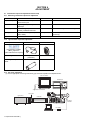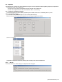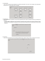
1
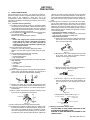
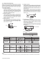
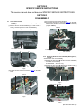
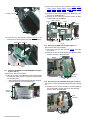
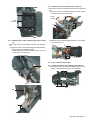
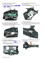
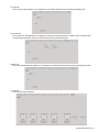
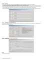
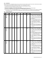
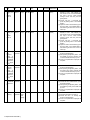
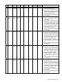
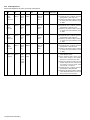
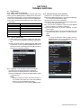
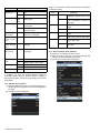
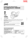
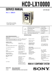
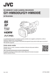
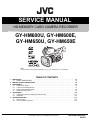
SERVICE MANUAL
HD MEMORY CARD CAMERA RECORDER
SERVICE MANUAL
2
2013
HC047<Rev.001>
GY-HM600U, GY-HM600E,
GY-HM650U, GY-HM650E
TIME
CODE
COPYRIGHT © 2013Note
JVC: KENWOOD Corporation
Lead free solder used in the board (material : Sn, Ag, In, Bi, melting point : 227 Centigrade)
TABLE OF CONTENTS
1
2
3
4
5
PRECAUTION. . . . . . . . . . . . . . . . . . . . . . . . . . . . . . . . . . . . . . . . . . . . . . . . . . . . . . . . . . . . . . . . . . . . . . . . . 1-3
1.1
SAFETY PRECAUTIONS . . . . . . . . . . . . . . . . . . . . . . . . . . . . . . . . . . . . . . . . . . . . . . . . . . . . . . . . . . 1-3
SPECIFIC SERVICE INSTRUCTIONS . . . . . . . . . . . . . . . . . . . . . . . . . . . . . . . . . . . . . . . . . . . . . . . . . . . . . . 1-5
DISASSEMBLY . . . . . . . . . . . . . . . . . . . . . . . . . . . . . . . . . . . . . . . . . . . . . . . . . . . . . . . . . . . . . . . . . . . . . . . 1-5
3.1
Center frame section . . . . . . . . . . . . . . . . . . . . . . . . . . . . . . . . . . . . . . . . . . . . . . . . . . . . . . . . . . . . . . 1-5
3.2
L Side cover assembly section. . . . . . . . . . . . . . . . . . . . . . . . . . . . . . . . . . . . . . . . . . . . . . . . . . . . . . . 1-7
3.3
R Side cover assembly section . . . . . . . . . . . . . . . . . . . . . . . . . . . . . . . . . . . . . . . . . . . . . . . . . . . . . . 1-8
3.4
Handle assembly section . . . . . . . . . . . . . . . . . . . . . . . . . . . . . . . . . . . . . . . . . . . . . . . . . . . . . . . . . . . 1-8
ADJUSTMENT . . . . . . . . . . . . . . . . . . . . . . . . . . . . . . . . . . . . . . . . . . . . . . . . . . . . . . . . . . . . . . . . . . . . . . . 1-12
4.1
Instruments required for adjustment and the setup . . . . . . . . . . . . . . . . . . . . . . . . . . . . . . . . . . . . . . 1-12
4.2
Adjustment . . . . . . . . . . . . . . . . . . . . . . . . . . . . . . . . . . . . . . . . . . . . . . . . . . . . . . . . . . . . . . . . . . . . . 1-13
TROUBLE SHOOTING . . . . . . . . . . . . . . . . . . . . . . . . . . . . . . . . . . . . . . . . . . . . . . . . . . . . . . . . . . . . . . . . . 1-21
5.1
Service menus . . . . . . . . . . . . . . . . . . . . . . . . . . . . . . . . . . . . . . . . . . . . . . . . . . . . . . . . . . . . . . . . . . 1-21
5.2
How to update the firmware . . . . . . . . . . . . . . . . . . . . . . . . . . . . . . . . . . . . . . . . . . . . . . . . . . . . . . . . 1-24
COPYRIGHT © 2013 JVC KENWOOD Corporation
No.HC047<Rev.001>
2013/2
SPECIFICATION
GY-HM600U, GY-HM600E
General
Power
GY-HM650U, GY-HM650E
DC 12 V
Power consumption
Approx. 10.2 W
Approx. 13.0 W
(during recording with backlight set to [STANDARD] while the view- (during recording with backlight set to [STANDARD] while the viewfinder is in
finder is in use)
use)
Mass
Approx. 2.4 kg (with battery)
Allowable operating temperature
Allowable operating humidity
0 °C to 40 °C (32 °F to 104 °F)
30 %RH to 80 %RH
Allowable storage temperature
-20 °C to 50 °C (-4 °F to 122 °F)
Approx. 2.5 kg (with battery)
Terminal Section
[HD/SD SDI] output terminal (480i or 576i:Downconverted 720p/1080i: embedded audio), BNC (unbalanced)
HD-SDI
SD-SDI
[INPUT1/INPUT2] terminal
Compliant with SMPTE 292 M
Compliant with SMPTE 259 M
[MIC]
-50 dBu, 3 kΩ, XLR (balanced), +48 V output (phantom power supply)
[LINE]
+4 dBu, 10 kΩ, XLR (balanced)
-22dBu, 10 kΩ, 3.5 mm stereo mini jack (unbalanced)
[AUX] terminal
[AV] terminal
4-pin 3.5 mm mini jack
Video signal
Audio signal
1.0 V (p-p)
-8 dBu (during reference level input), 1 kΩ (unbalanced)
[HEADPHONE] terminal
3.5 mm mini jack (stereo) x 1
[REMOTE] terminal
[USB] terminal
2.5 mm wired remote control
Ø2.5 mm mini jack (stereo)
Mini USB-B type, USB 2.0, miniB, slave function (mass storage class) only
[DEVICE]
[HOST]
-
[IN]
[OUT]
1.0 V(p-p) to 4.0 V(p-p) high impedance
2.0 ± 1.0 V(p-p) low impedance
Mini USB-B type, USB 2.0, miniB, slave function (mass storage class) only
USB-A type, USB2.0, network connection function only
[TC] terminal
Lens Section
Lens
Filter diameter
Fujinon F1.6, 23x, f=4.1 mm to 94.3 mm (35 mm conversion: 29 mm to 667 mm)
Ø72 mm
Camera Section
Image pickup device
Color separation prism
1/3-inch Progressive CMOS
F1.6, 3-color separation prism
Sync system
Internal sync (built-in SSG)
Optical filter
Gain
OFF, 1/4, 1/16, 1/64
-6dB, -3dB, 0dB, 3dB, 6dB, 9dB, 12dB, 15dB, 18dB, 21dB, 24dB, Lolux (30dB, 36dB), ALC
Electronic shutter
1/6 to 1/10000, EEI
Variable frame Rate
LCD monitor
2/30-60/30fps, 2/25-50/25fps, 2/24-60/24fps
3.5-inch LCD, 16:9 920K pixels
Viewfinder
0.45-inch LCOS, 1.22 Mpixels (852 x 480 x 3)
Storage Section
Supported media
Slots
SDHC/SDXC
x2
Video/Audio
Recording time
HD mode (MOV / MP4 / MXF: MPEG2)
Approx. 25 minutes (8 GB SD card, 35 Mbps, VBR mode)
Video recording file for- QuickTime File Format (For Final Cut Pro)/MP4 File Format
QuickTime File Format (For Final Cut Pro)/MP4 File Format/ MXF File Format
mat
Video: HQ mode
MPEG-2 Long GOP VBR, 35 Mbps (Max) MP@HL, 1920x1080/59.94i, 29.97p, 23.98p, 50i, 25p 1440x1080/59.94i, 50i 1280x720/59.94p, 29.97p,
23.98p, 50p, 25p
Video: SP mode
HD mode (AVCHD)
MPEG-2 Long GOP CBR, 18.3 Mbps MP@HL (720p)/25 Mbps MP@H14 (1080i) 1440x1080/59.94i, 50i 1280x720/59.94p, 50p
Video recording file for- AVCHD File Format
mat
Video: HQ mode
MPEG-4 AVC/H.264, 24 Mbps (Max) 1920x1080/59.94i, 50i
Video: SP mode
Audio
HD mode (MOV: H.264)
MPEG-4 AVC/H.264, 17 Mbps 1920x1080/59.94i, 50i
Dolby Digital 2ch, 48 kHz/16 Bit, 256 kbps
Video recording file for- mat
Video
-
MPEG-4 AVC/H.264, 35 Mbps (Max) 1920x1080/59.94i, 23.98p, 50i
Audio
LPCM 2ch, 48 kHz/16 Bit
-
QuickTime File Format
SD mode (MOV: H.264)
Video recording file for- QuickTime File Format
mat
Video
Audio
MPEG-4 AVC/H.264, 8 Mbps 720x480/59.94i (U model only), 720x576/50i (E model only)
LPCM 2ch, 48 kHz/16 Bit
Web mode (MOV: H.264)
Video recording file for- mat
QuickTime File Format
Video
-
MPEG-4 AVC/H.264, 1.2 Mbps 480x270/29.97p, 23.98p, 25p
Audio
-
µ-law 2ch, 16 kHz
Accessories
Warranty Card (U model only), Instructions, CDROM, AC Adapter, Power Cord (U model: 1, E model: 2), Battery, AV Cable, Clamp Filter, Wire Clamp,
Large Eyecup
1-2 (No.HC047<Rev.001>)
SECTION 1
PRECAUTION
1.1 SAFETY PRECAUTIONS
Prior to shipment from the factory, JVC products are strictly inspected to conform with the recognized product safety and electrical codes of the countries in which they are to be
sold.However,in order to maintain such compliance, it is equally
important to implement the following precautions when a set is
being serviced.
1.1.1 Precautions during Servicing
(1) Locations requiring special caution are denoted by labels
and inscriptions on the cabinet, chassis and certain parts of
the product.When performing service, be sure to read and
comply with these and other cautionary notices appearing
in the operation and service manuals.
(2) Parts identified by the symbol and shaded (
) parts
are critical for safety.
Replace only with specified part numbers.
NOTE :
Parts in this category also include those specified to
comply with X-ray emission standards for products
using cathode ray tubes and those specified for
compliance with various regulations regarding spurious radiation emission.
(3) Fuse replacement caution notice.
Caution for continued protection against fire hazard.
Replace only with same type and rated fuse(s) as specified.
(4) Use specified internal wiring. Note especially:
• Wires covered with PVC tubing
• Double insulated wires
• High voltage leads
(5) Use specified insulating materials for hazardous live parts.
Note especially:
• Insulation Tape
• PVC tubing
• Spacers
• Insulation sheets for transistors
• Barrier
(6) When replacing AC primary side components (transformers,
power cords, noise blocking capacitors, etc.) wrap ends of
wires securely about the terminals before soldering.
cathode ray tubes and other parts with only the specified
parts. Under no circumstances attempt to modify these circuits.Unauthorized modification can increase the high voltage value and cause X-ray emission from the cathode ray
tube.
(12) Crimp type wire connector In such cases as when replacing the power transformer in sets where the connections
between the power cord and power trans former primary
lead wires are performed using crimp type connectors, if
replacing the connectors is unavoidable, in order to prevent
safety hazards, perform carefully and precisely according
to the following steps.
• Connector part number :E03830-001
• Required tool : Connector crimping tool of the proper
type which will not damage insulated parts.
• Replacement procedure
a) Remove the old connector by cutting the wires at a
point close to the connector.Important : Do not reuse a connector (discard it).
cut close to connector
Fig.1-1-3
b) Strip about 15 mm of the insulation from the ends
of the wires. If the wires are stranded, twist the
strands to avoid frayed conductors.
15 mm
Fig.1-1-4
c) Align the lengths of the wires to be connected. Insert the wires fully into the connector.
Metal sleeve
Connector
Fig.1-1-1
(7) Observe that wires do not contact heat producing parts
(heatsinks, oxide metal film resistors, fusible resistors, etc.)
(8) Check that replaced wires do not contact sharp edged or
pointed parts.
(9) When a power cord has been replaced, check that 10-15
kg of force in any direction will not loosen it.
Power cord
Fig.1-1-5
d) As shown in Fig.1-1-6, use the crimping tool to
crimp the metal sleeve at the center position. Be
sure to crimp fully to the complete closure of the
tool.
1.2
5
2.0
5.5
Crimping tool
Fig.1-1-6
e) Check the four points noted in Fig.1-1-7.
Not easily pulled free
Crimped at approx. center
of metal sleeve
Conductors extended
Fig.1-1-2
(10) Also check areas surrounding repaired locations.
(11) Products using cathode ray tubes (CRTs) In regard to such
products, the cathode ray tubes themselves, the high voltage circuits, and related circuits are specified for compliance with recognized codes pertaining to X-ray emission.
Consequently, when servicing these products, replace the
Wire insulation recessed
more than 4 mm
Fig.1-1-7
(13) Battery replacement caution notice.
CAUTION RISK OF EXPLOSION IF BATTERY IS REPLACED BY AN INCORRECT TYPE.
DISPOSE OF USED BATTERIES ACCORDING TO THE
INSTRUCTIONS.
(No.HC047<Rev.001>)1-3
1.1.2 Safety Check after Servicing
Examine the area surrounding the repaired location for damage
or deterioration. Observe that screws, parts and wires have been
returned to original positions, Afterwards, perform the following
tests and confirm the specified values in order to verify compliance with safety standards.
(1) Insulation resistance test
Confirm the specified insulation resistance or greater between power cord plug prongs and externally exposed
parts of the set (RF terminals, antenna terminals, video and
audio input and output terminals, microphone jacks, earphone jacks, etc.).See table 1 below.
(2) Dielectric strength test
Confirm specified dielectric strength or greater between
power cord plug prongs and exposed accessible parts of
the set (RF terminals, antenna terminals, video and audio
input and output terminals, microphone jacks, earphone
jacks, etc.). See Fig.1-1-11 below.
(3) Clearance distance
When replacing primary circuit components, confirm specified clearance distance (d), (d') between soldered terminals, and between terminals and surrounding metallic
parts. See Fig.1-1-11 below.
(4) Leakage current test
Confirm specified or lower leakage current between earth
ground/power cord plug prongs and externally exposed accessible parts (RF terminals, antenna terminals, video and
audio input and output terminals, microphone jacks, earphone jacks, etc.).
Measuring Method : (Power ON) Insert load Z between
earth ground/power cord plug prongs and externally exposed accessible parts. Use an AC voltmeter to measure
across both terminals of load Z. See Fig.1-1-9 and following Fig.1-1-12.
a
Externally
exposed
accessible part
Z
A
b
c
V
Fig.1-1-9
(5) Grounding (Class 1 model only)
Confirm specified or lower grounding impedance between
earth pin in AC inlet and externally exposed accessible
parts (Video in, Video out, Audio in, Audio out or Fixing
screw etc.).Measuring Method:
Connect milli ohm meter between earth pin in AC inlet and
exposed accessible parts. See Fig.1-1-10 and grounding
specifications.
d
d'
Chassis
Power cord
primary wire
Exposed accessible part
AC inlet
Fig.1-1-8
Earth pin
Milli ohm meter
Grounding Specifications
Region
Grounding Impedance ( Z )
USA & Canada
Z
0.1 ohm
Europe & Australia
Z
0.5 ohm
Fig.1-1-10
AC Line Voltage
100 V
100 to 240 V
Region
Insulation Resistance (R)
Japan
110 to 130 V
USA & Canada
110 to 130 V
200 to 240 V
Europe & Australia
R
1M
1 M /500 V DC
R
R
12 M /500 V DC
10 M /500 V DC
Dielectric Strength
AC 1 kV 1 minute
AC 1.5 kV 1 minute
Clearance Distance (d), (d')
d, d '
3 mm
d, d '
4 mm
AC 1 kV 1 minute
AC 3 kV 1 minute
(Class )
AC 1.5 kV 1 minute
(Class )
d, d'
3.2 mm
d
4 mm
d'
8 m m (Power cord)
d'
6 m m (Primary wire)
Leakage Current (i)
a, b, c
Fig.1-1-11
AC Line Voltage
100 V
Japan
110 to 130 V
USA & Canada
110 to 130 V
220 to 240 V
Load Z
Region
Europe & Australia
i
1 mA rms
Exposed accessible parts
i
0.5 mA rms
Exposed accessible parts
2
i
i
0.7 mA peak
2 mA dc
Antenna earth terminals
50
i
i
0.7 mA peak
2 mA dc
Other terminals
1
0.15
1.5
Fig.1-1-12
NOTE :
These tables are unofficial and for reference only. Be sure to confirm the precise values for your particular country and locality.
1-4 (No.HC047<Rev.001>)
SECTION 2
SPECIFIC SERVICE INSTRUCTIONS
This service manual does not describe SPECIFIC SERVICE INSTRUCTIONS.
SECTION 3
DISASSEMBLY
3.1
Center frame section
3.1.1 Removing the L side cover assembly (See Figure 1, 2,
3 and 4)
(1) Remove the four screws A attaching the L side cover assembly, and then open the L side cover assembly.
A
(3) Pull out the wire from the SDI terminal.
(4) Pull out the wire from the connector CN3112 on the NETWORK board, and then remove the L side cover assembly
(only GY-HM650).
CN3112
A
L Side cover assembly
Fig.1
A
A
L Side cover assembly
SDI Terminal
Fig.4
L Side cover assembly
3.1.2 Removing the R side cover assembly (See Figure 5, 6,
7 and 8)
• Remove the L side cover assembly.
(1) Remove the four screws B and the one screw C attaching
the R side cover assembly.
Screw B: Short Screw C: Long
(2) Remove the two screws D attaching the handle cover (R)
and then remove the handle cover (R).
Fig.2
(2) Pull out the wire from the connector CN210 on the MAIN
board.
CN210
MAIN Board
B
R Side cover assembly B
Fig.5
R Side cover assembly
B
B
L Side cover assembly
Fig.3
Fig.6
(No.HC047<Rev.001>)1-5
(2) Pull out the wires from the connectors CN203, CN201,
CN207, CN214, CN208, CN213, CN209, CN212, CN202,
CN204, CN205, CN206, CN215 and CN216 on the MAIN
board.
(3) Remove the one screw F attaching the MAIN board, and
then remove the MAIN board.
(4) Remove the two screws G, and then remove the NETWORK board (only GY-HM650).
D
Handle cover (R)
D
CN214
CN208 CN207
CN215
CN201
C
CN203
H G
CN216
MAIN Board
Fig.7
(3) Pull out the FFC wire from the connector CN1412 on the
GAIN board, and then remove the R side cover assembly.
CN213
GAIN Board CN1412
CN209
CN202
CN212
CN204 G
CN206
CN205
Fig.10
3.1.4 Removing the SDSLOT board (See Figure 11)
• Remove the R side cover assembly.
(1) Pull out the wire from the connector CN809 on the SDSLOT board.
(2) Remove the two screws H attaching the SDSLOT board,
and then remove the SDSLOT board.
H
CN809
R Side cover assembly
Fig.8
3.1.3 Removing the MAIN board and NETWORK board (See
Figure 9 and 10)
• Remove the L side cover assembly.
(1) Remove the three screws E attaching the bracket (DCIN)
and heat sink plate, and then remove the bracket (DCIN)
and heat sink plate.
• When attaching the bracket (DCIN) and heat sink plate,
a bracket (DCIN) is under a heat sink plate.
E
Bracket
(DCIN)
H
Fig.11
3.1.5 Removing the rear assembly (See Figure 12 and 13)
• Remove the L side cover assembly and R side cover assembly
etc, .
(1) Remove the one screw J and the five screws K attaching
the rear assembly, and then remove the rear assembly.
Screw J: Silver Screw K: Black
Heat sink plate
E
Rear
assembly
E
Fig.9
J
Fig.12
1-6 (No.HC047<Rev.001>)
SDSLOT
Board
3.1.7 Removing the lens unit (See Figure 16 and 17)
• Remove the L side cover assembly and R side cover assembly
etc, .
(1) Remove the five screws M attaching the board bracket,
and then remove the board bracket.
K
Board
bracket
M
Rear
assembly
M
K
M
M
Fig.13
Fig.16
3.1.6 Removing the handle assembly (See Figure 14 and
15)
• Remove the L side cover assembly and R side cover assembly
etc, .
(1) Remove the four screws L attaching the handle assembly,
and then remove the handle assembly.
• When attaching the handle assembly, let two wires from
VF pass to the slit of a frame.
(2) Remove the five screws N attaching the lens unit, and then
remove the lens unit.
N
Handle assembly
N
Lens unit
Fig.17
3.2
L
L Side cover assembly section
3.2.1 Removing the Grip cover assembly (See Figure 1)
(1) Remove the seven screws A attaching the grip cover assembly, and then remove the grip cover assembly.
A
L
Fig.14
A
Fig.1
Slit
L
Fig.15
(No.HC047<Rev.001>)1-7
3.2.2 Removing the TC board (See Figure 2)
• Remove teh grip cover assembly.
(1) Pull out the wires from the connectors CN1212, CN1211,
CN1213 and CN1214 on the TC board.
(2) Remove the two screws B attaching the TC board, and
then remove the TC board.
CN1213
CN1214
3.3.2 Removing the R OPE unit (See Figure 2)
• Remove the GAIN board.
(1) Remove the eight screws B attaching the R OPE unit, and
then remove the R OPE unit.
B
CN1211
R OPE Unit
B
B
B
CN1212
B
Fig.2
TC Board
Fig.2
3.4
3.2.3 Removing the seesaw assembly (See Figure 3)
• Remove the grip cover assembly and TC board.
(1) Remove the two screws C attaching the seesaw assembly,
and then remove the seesaw assembly.
Handle assembly section
3.4.1 Removing the handle cover T (See Figure 1, 2 and 3)
(1) Remove the one screw A attaching the shoe spring, and
then remove the shoe spring.
Seesaw assembly
A
C
C
Fig.3
3.3
Shoe spring
Fig.1
R Side cover assembly section
3.3.1 Removing the GAIN board (See Figure 1)
(1) Pull out the wire from the connector CN1413 on the GAIN
board.
(2) Remove the three screws A attaching the GAIN board, and
then remove the GAIN board.
(2) Remove the two screws B attaching the shoe, and then remove the shoe.
(3) Remove the two screws C attaching the handle cover T.
Shoe
Handle cover T
GAIN Board CN1413
C
B
Fig.2
A
Fig.1
1-8 (No.HC047<Rev.001>)
C
(4) Pull out the FFC wire from the connector CN405 on the
HANDLE board, and then remove the handle cover T.
3.4.3 Removing the VF unit (See Figure 7, 8 and 9)
• Remove the handle cover T.
(1) Remove the four screws F attaching the ACC base, and
then remove the ACC base.
F
ACC Bace
F
Fig.7
(2) Remove the four screws G attaching the VF unit, and then
remove the VF unit.
CN405
VF Unit
G
HANDLE Board
Fig.3
3.4.2 Removing the GPS and HANDLE board (See Figure 4,
5 and 6)
• Remove the handle cover T.
(1) Remove the one screw D attaching the GPS. (only GYHM650)
Fig.8
D
VF Unit
GPS
Fig.4
(2) Remove the three screws E attaching the bracket and
HANDLE board.
G
G
E
Fig.9
HANDLE Board
Fig.5
(3) Pull out the wire from the connector CN407 on the HANDLE board, and then remove the GPS and HANDLE board.
3.4.4 Removing the XLR board (See Figure 10, 11, 12 and
13)
• Remove the handle cover T.
(1) Remove the six screws H attaching the XLR cover.
HANDLE Board
XLR Cover
H
H
CN407
Fig.10
Fig.6
(No.HC047<Rev.001>)1-9
(2) Remove the one screw L attaching the FFC, and then pull
out the wire from the connector CN1806.
(3) Remove the two screws M attaching the hinge, and then
remove the monitor assembly.
H
M
CN1806
M
L
Monitor
assembly
H
Fig.11
(2) Pull out the wires from the connectors CN506 and CN503
on the XLR board.
CN506
Fig.15
(4) Remove the one screw N, and then remove the front guard.
(5) Remove the six screws P and the one screw Q attaching
the OPE cover, and then remove the OPE cover.
Front guard
P
P
N
P
Q
CN503
Fig.12
(3) Remove the four screws J attaching the terminal, and then
remove the XLR board.
AVR Board
P
P
Fig.16
(6) Remove the two screws R attaching the volume knob, and
then remove the volume knob.
• When attaching the volume knob, turn in the direction of
an arrow, and attach so that “0” becomes a position of a
figure.
R
J
Fig.13
3.4.5 Removing the monitor assembly and AVR board (See
Figure 14, 15, 16, 17 and 18)
(1) Remove the two screws K attaching the joint cover, and
then remove the joint cover and hinge cover.
K Joint cover
Hinge
cover
K
Fig.14
1-10 (No.HC047<Rev.001>)
P
"0"
Fig.17
(7) Pull out the wires from the connectors CN301, CN305 and
CN302 on the AVR board.
(8) Remove the six screws S attaching the AVR board, and
then remove the AVR board.
S
S CN305
CN302
CN301
S
S
AVR Board
S
S
Fig.18
(No.HC047<Rev.001>)1-11
SECTION 4
ADJUSTMENT
4.1
Instruments required for adjustment and the setup
4.1.1 Measuring instruments required for adjustment
Instrument
Condition
Instrument
Condition
PC (Windows)
With an RS-232C compliant serial Audio tester
communication port.
Calibrated instrument.
Color TV monitor
Supporting HD(1080/60i), with an Speaker
HDMI input.
----------
Oscilloscope
100 MHz or higher (300 MHz is recom- DC power source
mended), calibrated instrument.
12V/1.7A or more, power source for light box.
Signal generator
Output level change is possible. AC adapter
(1kHz, 300Hz)
Used as a power source for the unit.
(Accessory)
Digital volt meter
Calibrated instrument.
Thermometer, Color thermometer, Illuminometer
4.1.2 Jigs and tools required for adjustment
Adjustment software
PC cable
Focus chart
QAM0099-002
YTU92001-018
Download from JS-NET
HM6xx_Adjust.exe
(.NET framework 4.0 required)
Light source
INF adjustment lens
(Collimator)
The halogen lamp of 3000K, YTU92001E
2600lx
White chart
88.9% of reflectance
4.1.3 Set up for adjustment
(1) Connect appropriate measuring instruments, jigs, and tools required for the adjustment item.
Color TV monitor
Oscilloscope
75
resistor for termination
Video signal
Focus chart
Light source
Collimator
To AUX
terminal
PC Cable
1-12 (No.HC047<Rev.001>)
4.2
Adjustment
The adjustment for this model is a special adjustment using a PC. Use the adjustment software (HM6xx_Adjust.exe) for adjustment.
(1) Preparation of SD card for adjustment
This camera can be changed to adjustment mode by using SD card for adjustment.
The SD card for adjustment has a file named PROJECT.ADJ in a root directory.
4.2.1 Installation of adjustment software
(1) Download adjustment software (HM6xx_Adjust.exe) from JS-NET, and store it in the arbitrary place in your PC.
4.2.2 The operation method
(1) Connect PC cable (QAM0099-002) to PC and a camera (AUX terminal).
(2) The screen as shown below will be displayed when launching the adjustment software.
(3) Set up a serial port.
(4) Operate the adjustment software by switching tabs according to the contents of adjustment.
4.2.2.1 ADJ Tab
If ADJ tab is chosen, the tab according to the adjustment item will appear.
(No.HC047<Rev.001>)1-13
(1) Composite tab
This is used for Composite signal adjustment. By operating each slide bar, each value can be changed, and by pressing the
[READ] button, the current preset value is acquirable.
(2) ZOOM MR Tab
This is used for Zoom ring adjustment. After pressing the [START] button, adjust by operating the Zoom ring, according to the
instruction.
• For FOCUS MR tab, ZOOM VR tab, and Z Tracking tab, adjust each article according to the instruction respectively. FOCUS
MR tab for Focus ring adjustment, ZOOM VR tab for Zoom potentiometer adjustment, and Z Tracking tab for Zoom tracking
adjustment.
(3) OIS Drv tab
This is used for OIS adjustment. After pressing the [START] button, adjust by rocking a camera, according to the instruction.
1-14 (No.HC047<Rev.001>)
(4) Ingain tab
This is used for Ingain adjustment. The adjustment is automatically performed when pressing the [START] button.
(5) AF Filter tab
This is used for AF Filter adjustment. The adjustment needs to be performed under the condition of ND 1/16 and ND 1/64.
It is automatically performed under each condition when pressing each [START] button.
(6) BPD Tab
This is used for White Blemish adjustment. The adjustment is automatically performed when pressing the [START] button.
(7) Audio tab
This is used for audio adjustment.
(No.HC047<Rev.001>)1-15
4.2.2.2 EEP Tab
It is used when reading and writing the data of EEPROM which each microcomputer (CC, BE, IF) has managed.
• For example, when reading the data of EEPROM which BE microcomputer has managed, input an address to read into the Adrs
colummn on the left side of the [READ] button of BE Write, and press the [READ] button.
• When writing data to EEPROM which BE microcomputer has managed, input an address to write into the Adrs column on the left
side of the [Write] button of BE Write, and the data to write into the Data column, and then press the [Write] button.
• Also for the EEPROM which CC microcomputer and IF microcomputer have managed, it is the same as that of BE microcomputer.
4.2.2.3 SETTING1 Tab and SETTING2 Tab
This is used for setting parameters to the camera. Input a parameter to set to the camera into a relevant column, respectively, and
then press the relevant [Write] button.
4.2.2.4 OTHERS Tab
Each reset is assigned here and it is frequently-used.
NOTE:
Other tabs are not used.
1-16 (No.HC047<Rev.001>)
4.2.3 Preparation
When the camera is in the adjustment mode, the red “P” letter can be seen at the top of the LCD screen, and this mode is retained
until ALL Reset is performed with the adjustment software, even if shutting off the camera.
(1)
(2)
(3)
(4)
(5)
Insert the SD card for adjustment into slot B, and remove it after flashing slot B indicator.
Connect a JLIP cable to an AUX terminal of the camera.
When the clock setting screen of the camera is displayed, press the [SET] button of the camera to skip it.
Choose an OTHERS tab, press the [0x01] button of the MENU Reset to reset the menu.
In the case of the "U" model, Master Black is set to "-3". You need to set this to "0" for adjustment. the procedure is as follows;
Choose EEP tab, input 7 into Adrs column of the BE Write, input 32 into Data column and then press the [Write] button.
4.2.4 Camera adjustment
No. Adjustment Adjustment Jig
item
type
Signal
Adjustment standard Adjustment Adjustment Procedure
point
value range default value
1
Composite Manual ad- Oscillo- Built-in
Composite
analog out- justment
scope color bar output
put
CGAIN
60Hz U
0.286V
0-255
112
(0x70)
(1) Set Record Format to 1920 x 1080,
60i(HQ) or 1440 x 1080, 60i(HQ), if it
has not been set so. Choose SETTING1
tab, input 0 into the "Video Format
Change" column and then press the
[Write] button.
(2) Set SETUP to ON, if it has not been set
so. Choose SETTING1 tab, input 1 into
the "Composite Setup On/Off" column
and then press the [Write] button.
(3) Choose ADJ tab -> Composite tab,
press the [Read] button of the CGAIN
60HZ U.
(4) Adjust the value to the standard by operating the slider of the CGAIN 60HZ U,
with observing the wave form on the oscilloscope.
2
Composite Manual ad- Oscillo- Built-in
Composite
analog out- justment
scope color bar output
put
YGAIN
60Hz U
1.0V
0-255
162
(0xA2)
(1) Set Record Format to 1920 x 1080,
60i(HQ) or 1440 x 1080, 60i(HQ), if it
has not been set so. Choose SETTING1
tab, input 0 into the "Video Format
Change" column and then press the
[Write] button.
(2) Set SETUP to ON, if it has not been set
so. Choose SETTING1 tab, input 1 into
the "Composite Setup On/Off" column
and then press the [Write] button.
(3) Choose ADJ tab -> Composite tab,
press the [Read] button of the YGAIN
60HZ U.
(4) Adjust the value to the standard by operating the slider of the YGAIN 60HZ U,
with observing the wave form on the oscilloscope.
3
Composite Manual ad- Oscillo- Built-in
Composite
analog out- justment
scope color bar output
put
YGAIN
60Hz I
1.0V
0-255
175
(0xAF)
(1) Set Record Format to 1920 x 1080,
60i(HQ) or 1440 x 1080, 60i(HQ), if it
has not been set so. Choose SETTING1
tab, input 0 into the "Video Format
Change" column and then press the
[Write] button.
(2) Set SETUP to OFF, if it has not been set
so. Choose SETTING1 tab, input 0 into
the "Composite Setup On/Off" column
and then press the [Write] button.
(3) Choose ADJ tab -> Composite tab,
press the [Read] button of the YGAIN
60HZ I.
(4) Adjust the value to the standard by operating the slider of the YGAIN 60HZ I,
with observing the wave form on the oscilloscope.
(No.HC047<Rev.001>)1-17
No. Adjustment Adjustment Jig
item
type
Signal
Adjustment standard Adjustment Adjustment Procedure
point
value range default value
4
Composite Manual ad- Oscillo- Built-in
Composite
analog out- justment
scope color bar output
put
CGAIN
50Hz E
0.30V
0-255
113
(0x71)
(1) Set Record Format to 1920 x 1080,
50i(HQ) or 1440 x 1080, 50i(HQ), if it
has not been set so. Choose SETTING1
tab, input 1 into the "Video Format
Change" column and then press the
[Write] button.
(2) Choose ADJ tab -> Composite tab,
press the [Read] button of the CGAIN
50HZ E.
(3) Adjust the value to the standard by operating the slider of the CGAIN 50HZ E,
with observing the wave form on the oscilloscope.
5
Composite Manual ad- Oscillo- Built-in
Composite
analog out- justment
scope color bar output
put
YGAIN
50Hz E
1.0V
0-255
171
(0xAB)
(1) Set Record Format to 1920 x 1080,
50i(HQ) or 1440 x 1080, 50i(HQ), if it
has not been set so. Choose SETTING1
tab, input 1 into the "Video Format
Change" column and then press the
[Write] button.
(2) Choose ADJ tab -> Composite tab,
press the [Read] button of the YGAIN
50HZ E.
(3) Adjust the value to the standard by operating the slider of the YGAIN 50HZ E,
with observing the wave form on the oscilloscope.
6
ZOOM Ring Semiauto
MR
adjustment
(Perform
before "8.
ZOOM Ring
TELE/WIDE
potentiometer" adjustment)
-
(1) Choose ADJ tab -> ZOOM MR tab,
press the [START] button.
(2) After pressing the [START] button, turn
the ZOOM ring quickly clockwise and
counterclockwise alternately by hand.
(3) It will be completed when displayed as
Complete.
7
FOCUS
Semiauto
Ring MR
adjustment
(Perform
before "8.
ZOOM Ring
TELE/WIDE
potentiometer" adjustment)
-
(1) Choose ADJ tab -> FOCUS MR tab,
press the [START] button.
(2) After pressing the [START] button, turn
the FOCUS ring quickly clockwise and
counterclockwise alternately by hand.
(3) It will be completed when displayed as
Complete.
8
ZOOM ring Semiauto
TELE/WIDE adjustment
potentiometer
-
(1) Set the ZOOM ring to the TELE end.
(2) Choose ADJ tab -> ZOOM VR tab, press
the [START] button.
(3) After pressing the [START] button, turn
the ZOOM ring slowly to the WIDE end
by hand.
(4) It will be completed when displayed as
Complete.
9
ZOOM
Tracking
Automatic Colliadjustment mator
LED
lighting
(1) Attach the Collimeter to the Lens.
(2) Check the illumination is 19±3Lux.
(3) Choose ADJ tab -> Z Tracking tab,
press the [START] button.
(4) It will be completed when displayed as
Complete.
1-18 (No.HC047<Rev.001>)
No. Adjustment Adjustment Jig
item
type
10 OIS Drive
Automatic adjustment
11 INGAIN and Automatic
ANALOGGAIN
Mini
adjustment studio
12 AF Filter ND Semiauto
1/16
Mini
adjustment studio
13 AF Filter ND Semiauto
1/64
Mini
adjustment studio
14 White blem- Automatic
ish
adjustment
-
Signal
Adjustment standard Adjustment Adjustment Procedure
point
value range default value
-
(1) Choose ADJ tab -> OIS Drv tab,
press the [START] button.
(2) After pressing the [START] button,
adjust so that the shake of a monitor
screen comes to minimum, while vibrating a camera by hand.
(3) It will be completed when displayed
as Complete.
White
chart
(1) Prepare an adjustment environment of 3000K (Mini studio or
something).
(2) Set Record Format to 1920 x 1080,
24p(HQ), if it has not been set so.
Choose SETTING1 tab, input 4 into
the "Video Format Change" column
and then press the [Write] button.
(3) Choose ADJ tab -> Ingain tab,
press the [START] button.
(4) It will be completed when displayed
as Complete.
White
chart
(1) Set ND filter to the 1/16 position.
(2) Set Record Format to 1920 x 1080,
60i(HQ) or 1440 x 1080, 60i(HQ), if
it has not been set so. Choose
SETTING1 tab, input 0 into the "Video Format Change" column and
then press the [Write] button.
(3) Choose ADJ tab -> AF Filter tab,
press the [START] button of ND 1/
16.
(4) It will be completed when displayed
as Complete.
White
chart
(1) Set ND filter to the 1/64 position.
(2) Set Record Format to 1920 x 1080,
60i(HQ) or 1440 x 1080, 60i(HQ), if
it has not been set so. Choose
SETTING1 tab, input 0 into the "Video Format Change" column and
then press the [Write] button.
(3) Choose ADJ tab -> AF Filter tab,
press the [START] button of ND 1/
64.
(4) It will be completed when displayed
as Complete.
- (IRIS
CLOSE)
(1) Wait about 30 minutes for pre-heating the camera.
(2) Set Record Format to 1920 x 1080,
60i(HQ) or 1440 x 1080, 60i(HQ), if
it has not been set so. Choose
SETTING1 tab, input 0 into the "Video Format Change" column and
then press the [Write] button.
(3) Choose ADJ tab -> BPD tab, press
the [START].
(4) It will be completed when displayed
as Complete.
(No.HC047<Rev.001>)1-19
4.2.5 Audio adjustment
Perform this adjustment only when you change a microphone.
No. Adjustment Adjustment Jig
item
type
Signal
1
AUDIO XLR Manual adLevel
justment
INPUT1
LINE Level
Audio
signal
generator
1kHz
ADC DATA -20dBFS ±8
(+4dBu)
(3277 as
decimal
value)
(1) Switch XLR1 input to LINE.
(2) Choose ADJ tab -> Audio tab, press the
[Read] button of XLR LINE1 LEV.
(3) Adjust by operating the slider so that the
on-screen level meter indication comes
to -20dB.
2
AUDIO XLR Manual adLevel
justment
INPUT1
MIC Level
Audio
signal
generator
1kHz
ADC DATA -20dBFS ±8
(-50dBu)
(3277 as
decimal
value)
(1) Switch XLR1 input to MIC.
(2) Choose ADJ tab -> Audio tab, press the
[Read] button of XLR MIC1 LEV.
(3) Adjust by operating the slider so that the
on-screen level meter indication comes
to -20dB.
3
AUDIO XLR Manual adLevel
justment
INPUT2
LINE Level
Audio
signal
generator
1kHz
ADC DATA -20dBFS ±8
(+4dBu)
(3277 as
decimal
value)
(1) Switch XLR2 input to LINE.
(2) Choose ADJ tab -> Audio tab, press the
[Read] button of XLR LINE2 LEV.
(3) Adjust by operating the slider so that the
on-screen level meter indication comes
to -20dB.
4
AUDIO XLR Manual adLevel
justment
INPUT2
MIC Level
Audio
signal
generator
1kHz
ADC DATA -20dBFS ±8
(-50dBu)
(3277 as
decimal
value)
(1) Switch XLR2 input to MIC.
(2) Choose ADJ tab -> Audio tab, press the
[Read] button of XLR MIC2 LEV.
(3) Adjust by operating the slider so that the
on-screen level meter indication comes
to -20dB.
5
300Hz
LINE OUT
AUDIO
Manual ad- 2CH
Built-in mi- justment
Audio (400 to
crophone
Analyz- 700mV)
er,
Sound
source,
Speaker
1-20 (No.HC047<Rev.001>)
Adjustment standard Adjustment Adjustment Procedure
point
value range default value
Rch=Lch ±8
(1) Set both CH1 INPUT SELECT and CH2
INPUT SELECT to INT.
(2) Put a camera so that a built-in microphone faces straight to the speaker,
apart 20 cm or more from each other.
(3) Output the 300Hz sine wave from the
speaker. Adjust the audio output level of
the speaker so that the audio output
comes to 400 ~ 700 mVrms.
(4) Choose ADJ tab -> Audio tab, press the
[Read] button of MIC BALANCE.
(5) Adjust by operating the slider so that the
value differences between Lch Eva Val
and Rch Eva Val are minimized.
SECTION 5
TROUBLE SHOOTING
5.1 Service menus
5.1.1 Modes required in servicing
While holding down the specified button (FOCUS ONE PUSH
AUTO), press the [MENU] button to display the first layer menu
of the service menu hierarchy. The items in the first layer vary according to the specified button being held when the [MENU] button is pressed. (Characters are displayed on LCD monitor screen
or View finder.)
MENU Item
Contents
Advanced Function
Camera settings, Blemish detect etc.
Service Function
Test signal, Battery voltage settings etc.
DIP SW
DIP SW Menu
Hour Meter
Hour meter indication
Others
All reset
5.1.2 Service menu Display
(1) While holding down the [FOCUS ONE PUSH AUTO] button, and then press the [USER1] + [USER2] + [MENU] buttons.
(2) And in the state which has pressed [FOCUS ONE PUSH
AUTO] button, a press on [USER3]+[MENU] button will display Service menu. (Pressing a [FOCUS ONE PUSH AUTO] button is continued to the last.)
5.1.4 Advanced Function menu operation
(1) Refer to 5.1.2 to display the Service menu.
(2) Select the [Advanced Function...], then press the [Set] button or the [Cross-Shaped] button (right).
(3) Advanced Function menu is displayed.
(4) Select the item to be changed, then press the [Set] button
or the [Cross-Shaped] button (right).
(5) A choice screen is displayed. Press the [Cross-Shaped]
buttons (up/down) to change the parameter.
(6) Press the [Set] button to set the parameter. A choice
screen closes.
(7) If the [CANCEL] button or the [Cross-Shaped] button (left)
is pressed, it will return to the layer on one and will end a
setup.
NOTE:
• To cancel the parameter setting change, press the
[CANCEL] button or the [Cross-Shaped] button (left)
while the choice screen is displaying.
5.1.3 Operation in the first layer of the service menu
(1) The first layer of each service menu is displayed.
(2) Press the [Cross-Shaped] buttons to select the item.
(3) Press the [Set] button or the [Cross-Shaped] button (right)
to select the item.
NOTE:
• During recording, the service menu does not start up.
• To go back to the upper layer, press the [CANCEL]
button or the [Cross-Shaped] button (left).
• To cancel the service menu, press the [MENU] button.
(No.HC047<Rev.001>)1-21
Item
Pixel Compen
Det (FA) *1
Parameter
Cancel
Does not execute blemish detection.
Execute
Executes blemish detection.
FAW Sensitivity Slow
Midle
Fast
Sets the response speed of the
FAW control.
Silent Zoom
Off
ZOOM speed is not late.
It is not quiet.
On
ZOOM speed is slow.
It becomes quiet.
AF Mode (Does 0-255
not function.)
The operational mode (evaluation
area) of AF is changed.
AF
Sensitivity 0
(Does not func- 1
tion.)
2
The sensitivity of AF is changed.
AF Frequency 0
(Does not func- 1
tion.)
2
The frequency of AF filter is
changed.
AF M.O.D (Does 0
not function.)
1
5
10
20
The shortest object distance of AF
is changed.
C.Rec Audio
Fade
Off
No AUDIO FADE in STBY↔REC.
On
AUDIO FADE in STBY↔REC.
Loop Rec
Off
No LOOP REC.
On
Endless LOOP REC.
SDI Out..
Item
OutType
LTC
VITC
Audio
Refer to the 5.1.5
(Bold is the factory setting.)
*1 Available only when the Camera Resolution setting is
1920x1080, and the Frame & Bit Rate setting is 60i(HQ) or
50i(HQ). Except them, it becomes a gray display and execution
is impossible.
5.1.5 SDI Out menu operation
(1) Open the Advanced Function menu, select the [SDI Out...],
and then press the [Set] button or the [Cross-Shaped] button (right).
(2) The SDI Out menu is displayed.
1-22 (No.HC047<Rev.001>)
Refer to 5.1.4 Advanced Function Menu because the operations
are almost the same.
Parameter
Consumer
The bit in the CONSUMER mode of
AES/EBU is added to a SDI output.
Pro
The bit in the PROFESSIONAL
mode of AES/EBU is added to a
SDI output.
Off
Does not add the LTC data on SDI
output.
On
Adds the LTC data on SDI output.
Off
Does not add the VITC data on SDI
output.
On
Adds the VITC data on SDI output.
Off
Does not add the audio data and TC
data on SDI output.
On
Adds the audio data and TC data on
SDI output.
(Bold is the factory setting.)
5.1.6 Service Function menu operation
(1) Refer to 5.1.2 to display the Service menu.
(2) Select the [Service Function...], and then press the [Set]
button or the [Cross-Shaped] button (right).
(3) The Service Function menu is displayed.
Refer to 5.1.4 Advanced Function Menu because the operations
are almost the same.
Item
Parameter
Pixel Com- Off
pen
*1
On
Check
Test Signal Off
FPGA1
Does not correct the detected white
blemish.
Corrects the detected white blemish.
Light up the pixels which are the detected white blemish.
No output test signal.
Outputs FPGA1 signal.
1 to 32
FB1
Outputs FB1 signal.
1 to 5
FPGA2
Outputs FPGA2 signal.
LCD/VF Bars, Check Field A, Check
Field B
FB2
Outputs FB2 signal.
1 to 5
DC
Shut- 10.4V
down
Shutdown voltage is set up at 0.1V
step at the time of DC power supply
use. (10.0V to 12.0V)
BATT Shut- 6.3V
down
Shutdown voltage is set up at 0.1V
step at the time of battery use. (6.3V
to 7.2V)
BATT Alarm 6.6V
Display voltage of battery alarm is set
up at 0.1V step at the time of battery
use. (6.3V to 7.2V)
(Bold is the factory setting.)
*1 This mode is automatically set to ON when the power is turned
ON. The OFF mode is enabled only after it is set to OFF on this
screen until the power is turned OFF.
5.1.7 DIP SW Menu Operation
(1) Refer to 5.1.2 to display the Service menu.
(2) Select the [DIP SW...], and then press the [Set] button or
the [Cross-Shaped] button (right).
(3) The DIP SW is displayed.
NOTE:
ALL DIP switches are factory use only. These DIP switches
are not used for repair or maintenance. Therefore all DIP
Switch settings which are shown below should not be
changed. And do not forget to return to the initial position, if
setting was changed.
Refer to 5.1.4 Advanced Function Menu because the operations
are almost the same.
Item
DIP SW ALL
RESET
DIP SW 0-15
Parameter
CANCEL
Cancel to reset all DIPSW
settings.
EXECUTE
Execute to reset all DIPSW
settings.
DIP SW 0 to 15
OFF Change prohibited.
DIP SW 16-23 DIP SW 16 to 23 OFF Change prohibited.
DIP SW 24-31 DIP SW 24 to 31 OFF Change prohibited.
DIP SW 32-47 DIP SW 32 to 47 OFF Change prohibited.
DIP SW 48-63 DIP SW 48 to 63 OFF Change prohibited.
(Bold is the factory setting.)
(No.HC047<Rev.001>)1-23
5.1.8 Hour Meter menu operation
(1) Refer to 5.1.2 to display the Service menu.
(2) Select the [Hour Meter...], and then press the [Set] button
or the [Cross-Shaped] button (right).
(3) The Hour Meter menu is displayed.
Refer to 5.1.4 Advanced Function Menu because the operations
are almost the same.
Item
Parameter
ALL Cancel Standard setting.
Reset Reset Resets all EEP-ROM data to default settings
except adjustment data and hour meter data.
(Bold is the factory setting.)
5.2
Refer to 5.1.4 Advanced Function Menu because the operations
are almost the same.
Item
Parameter
Power
000000
Displays the power hour meter.
Reset
Resets the power hour meter.
Fan
000000
Displays the fan hour meter.
Reset
Resets the fan hour meter.
Slot Eject 000000
Reset
Displays the slot A and B eject count.
Resets the slot A and B eject count.
5.1.9 Others menu operation
(1) Refer to 5.1.2 to display the Service menu.
(2) Select the [Others...], and then press the [Set] button or the
[Cross-Shaped] button (right).
(3) The Others menu is displayed.
How to update the firmware
NOTE:
• The update should connect both of battery with an AC adaptor.
• Remove the USB cable, HDMI cable, component cable and
A/V OUT cable.
• Do not turn OFF the power during the update.
• Update time is about 3 minutes.
5.2.1 Preparation (Copy the firmware to SD/SDHC memory
card)
NOTE:
• Please do not use the SDHC memory card for record.
• Format the SD memory card on the GY-HM600/650 if formatting is required.
(1) Download the update file from download site and unzip it to
a PC. (It unzip, when a file is double-clicked.)
(2) Insert the SD/SDHC memory card to the PC and confirm
that no file is in the SD/SDHC memory card. If there are
some files, delete them.
(3) Copy the unzipped update file to the SD/SDHC memory
card. Check that the directory in SD card is as follows.
\\PRIVATE\JVC\GY-HM600 (In case of GY-HM650, \\PRIVATE\JVC\GY-HM650)
5.2.2 Update procedure
(1) Check that the power switch is come by OFF. While pressing the [FOCUS PUSH AUTO] and [MENU/THUMB (side)]
buttons, turn ON the power.
The version of the present firmware is displayed on VF.
NOTE:
Nothing is displayed on LCD.
VF screen
Firmware Update
Current Version: Vxxxx
Please Plug AC and Battery.
(2) Insert the SD/SDHC memory card into the card slot B. (Can
not be updated with slot A.)
1-24 (No.HC047<Rev.001>)
(3) The updating is started automatically, after the SD/SDHC
memory card was inserted.
• A progress bar is displayed on VF during update.
• SLOT A LED goes out and SLOT B LED carries out red
blink irregularly.
5.2.4 Update error
When update cannot be performed by a certain cause, it is displayed to VF as "Update Error !".
SLOT A LED and SLOT B LED blink by turns.
VF screen
VF screen
Updating ...
Update Error !
Don't Turn Power Off
In this case, there is possibility of failure of apparatus.
(4) After update is completed, it is displayed on VF as "Complete". (Update time is about 3 minutes.)
SLOT A LED and SLOT B LED carry out green blink simultaneously slowly.
VF screen
Firmware Update
Complete
(5) Remove the SD/SDHC memory card.
(6) Update is ended. Remove an AC adaptor and a battery.
Turn OFF the power and turn it ON again.
5.2.3 When update cannot be performed
When update cannot be performed by a certain cause, it is displayed to VF as "Update can't be Executed !".
SLOT A LED and SLOT B LED blink by turns.
VF screen
Update can't be Executed !
In this case, check whether an update file is a thing of an applicable model.
(No.HC047<Rev.001>)1-25
JVC KENWOOD Corporation
Professional Systems Business Group, Business Solution Div.
(No.HC047<Rev.001>)
Printed in Japan
VSE