1
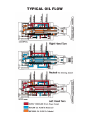
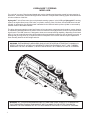
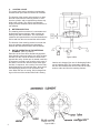
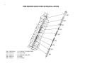
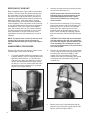
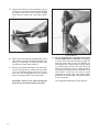
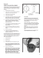
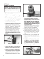
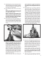
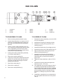
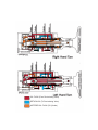
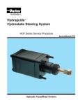
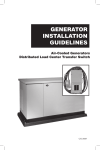
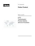
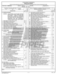
Hydraulics
Hydraguide™
Hydrostatic Steering System
HGB Service Manual
Service Manual 2752
Hydraulic Pump/Motor Division
TYPICAL OIL FLOW
Table of Contents
Section I
System Operation .................................................................................................................page 2
Design and Function.............................................................................................................page 2
Control Valve ........................................................................................................................page 3
Metering Section...................................................................................................................page 3
Rotor Operation ....................................................................................................................page 3
Power Steering Operation ....................................................................................................page 4
Manual Steering Operation...................................................................................................page 4
Exploded View ......................................................................................................................page 5
Service Parts List..................................................................................................................page 6
Pressure Dam Check Installation .........................................................................................page 7
Section II
Service Procedure ................................................................................................................page 8
Work Conditions ...................................................................................................................page 8
Seal Replacement Instructions .............................................................................................page 8
Servicing of HGB Unit...........................................................................................................page 8
Disassembly Procedure........................................................................................................page 8
Section III
Inspection and Replacement ..............................................................................................page 11
Section IV
Assembly Procedure...........................................................................................................page 12
Filling and Air Bleeding System ..........................................................................................page 15
Hydraulic Fluid ....................................................................................................................page 15
Column Assembly and Disassembly Procedures ...............................................................page 16
Tips for Maintaining the System .........................................................................................page 17
Exploded View ....................................................................................................................page 19
!
WARNING
FAILURE OR IMPROPER SELECTION OF
IMPROPER USE OF THE PRODUCTS
AND/OR SYSTEMS DESCRIBED HEREIN
OR RELATED ITEMS CAN CAUSE DEATH,
PERSONAL INJURY AND PROPERTY DAMAGE.
This document and other information from Ross
Operation, its subsidiaries and authorized distributors provide product and/or system options for further investigation by users having technical exper-
tise. It is important that you analyze all aspects of
your application and review the information concerning the product or system in the current product catalog. Due to the variety of operating conditions and applications for these products or systems, the user, through its own analysis is and
testing, is solely responsible for making the final
selection of the products and systems and assuring that all performance, safety and warning
requirements of the application are met.
The products described herein, including without
limitation, product features, specifications, designs,
availability and pricing, are subject to change by
Ross Operation and its subsidiaries at any time
without notice.
HYDRAGUIDE™ STEERING
MODEL HGB
For over half a century, Ross has anticipated and met the changing and increasing needs for better steering of
automotive, construction, industrial and agricultural machines. This hydrostatic steering system described herein
is further evidence of this fact.
Hydraguide™ is the Ross name given to hydrostatic steering systems. In the HGB type Hydraguide™ steering
system, an engine-driven pump, relief valve, or cylinder, reservoir, filter, fluid lines, and an HGB control unit are
needed. An automotive type steering wheel is attached to the HGB unit and the power cylinder is connected by
suitable means to the steered wheels.
The driver has power steering control at all times, so long as system components work together, system integrity
is maintained, and adequate fluid is present. If there is a failure in the high-pressure circuit, a loss of power steering will result. The HGB, however, is designed to have some manual steering capability, depending on the installation. If you can’t manually steer the vehicle without using extraordinary measures, such as leaving your seat, or
pushing with your legs, don’t try it. Repair the failure in the power circuit. Some vehicles may be impossible to
steer manually because of their weight and size.
WARNING: EXTRAORDINARY MEASURES SHOULD NOT BE USED IN ATTEMPTING TO MANUALLY
STEER THE VEHICLE, AS THEY MAY GENERATE FORCES IN EXCESS OF 125 FT. LBS., THEREBY
DAMAGING THE UNIT INTERNALLY, WHICH COULD RESULT IN A COMPLETE LOSS OF STEERING.
WARNING: ALL STEERING MECHANISMS ARE LIFE AND LIMB ITEMS. AS SUCH, IT IS IMPERATIVE
THAT THE INSTRUCTIONS IN THIS BOOKLET ARE FOLLOWED TO THE LETTER. FAILURE TO
OBSERVE THE PROCEDURES SET OUT IN THIS PAMPHLET MAY RESULT IN LOSS OF STEERING.
1
SECTION I
A. SYSTEM OPERATION
This literature with the illustrations shown covers a
standard basic design of the HGB unit. Variations
may be engineered to suit special requirements.
Satisfactory performance of this system requires a
well engineered installation designed for the particular type of vehicle and the type and kind of
service for which it will be used. Ross Engineering
advice and assistance is available and we welcome
requests.
The description of the operation of the HGB unit and
the illustrations explain the functioning of the system
for the utilization of the hydraulic power generated by
the engine-driven pump for power steering.
Information on the required engine-driven pump
capacity and the power cylinder size and connecting
lines are provided through engineering contacts. A
balanced cylinder design is preferred.
Figure HGB-1
B. DESIGN & FUNCTION
The HGB unit consists of a fluid control valve section
and a fluid metering section which are hydraulically
and mechanically inter-connected.
2
C. CONTROL VALVE
The control valve section contains a mechanically
actuated linear spool which is torsion bar centered.
The function of the control valve section is to direct
the fluid to and from the metering section, to and
from the cylinder, and to regulate the pressure supplied to the cylinder. The valve is provided with
unique pressure chambers which insure effective circuit isolation.
D. METERING SECTION
The metering section consists of a commutator and
bi-directional gerotor element, which contains an
orbiting rotor and a fixed stator. The commutator
rotates at orbit speed with the rotor and channels the
fluid to and from the rotor set and the valve section.
The function of the metering section is to meter the
oil to the cylinder, maintaining the relationship
between the hand wheel and the steered wheels.
E.
ROTOR OPERATION IN THE METERING
ELEMENT (See Fig. HGB-3)
Each lobe of the rotor has a diametrically opposite
lobe, therefore, when one lobe is in a cavity its opposite lobe is at the crest of the stator’s convex form
opposite the cavity. As the rotor is rotated, each lobe
in sequence is moved out of its cavity to the crest of
the stator’s convex form and this forces each opposite lobe, in sequence, into a cavity. Due to the interaction between the rotor and the stator, there are 42
fluid discharging actions in one revolution of the
rotor. When the rotor is moving, fluid is always flowing out of three of the cavities while fluid is flowing
3
Figure HGB-2
into three other cavities, and one of the cavities is
inactive as it changes from one of discharging fluid to
one of admitting fluid. The commutator rotates with
the rotor and channels the fluid from and to the valve
section, and to and from the metering element.
Figure HGB-3
F.
POWER STEERING OPERATION
When the spool is in center or neutral position, the
hydraulic oil from the engine-driven pump circulates
through the valve section, directly back to the reservoir with sufficient pressure only to overcome friction
of valve channels and lines. There is no circulation of
engine-driven pump oil to or from the cylinder. Note
the center diagram showing neutral position
(Reference the typical oil flow diagram on the back of
the front cover) on which no directional arrows
appear in the metering channels. The oil pressure at
the two cylinder ports is equal and produces ineffective forces in the cylinder.
commutator. The exhaust side of the rotor set is connected, through the commutator, to one side of the
cylinder while the other side of the cylinder is connected to the reservoir. (See Figures HGB-1 and 2).
In order to accomplish a power steering maneuver,
the operator must rotate the steering wheel in the
direction of the steering maneuver. The initial rotation
of the steering wheel rotates the input shaft which
tends to rotate the drive link and rotor set through the
torsion bar centering spring. Rotation of the rotor set
and spool which are coupled by the drive link, is
resisted by the cylinder pressure required to overcome the steering forces. As the input shaft is rotated relative to the spool, the centering spring is torsionally deflected. Axial shift of the spool is inducted
by the ball which is captive in the spool and engaged
in the helical groove provided in the input shaft.
G. MANUAL STEERING OPERATION
In the absence of system pressure, the driver's manual effort displaces the spool axially. When the spool
is displaced within the body, fluid channels are
selected connecting the rotor set, which is now acting as a pump, via the commutator to one side of the
cylinder. The return flow from the other side of the
cylinder is channeled through a recirculation valve so
that the oil will flow to the intake side of the rotor set
via the commutator instead of back to the reservoir.
(See. Figure HGB-5) The recirculation valve is a ball
check valve in a channel connecting the return flow
chamber to the engine-driven pump pressure inlet
chamber. The recirculation valve is closed during
power operation.
When the spool is axially displaced within the body,
fluid channels are selected connecting the enginedriven pump to the intake side of the rotor set via the
Further axial displacement of the spool results in
increased system pressure to provide the level of
pressure required. A portion or all of the hydraulic
fluid at the required pressure from the engine-driven
pump, depending upon the speed of steering, is
directed to the cylinder via the metering section,
using cylinder movement to accomplish the steering
maneuver.
WARNING: EXTRAORDINARY MEASURES
SHOULD NOT BE USED IN ATTEMPTING TO
MANUALLY STEER THE VEHICLE, AS THEY MAY
GENERATE FORCES IN EXCESS OF 125 FT.
LBS., THEREBY DAMAGING THE UNIT INTERNALLY, WHICH COULD RESULT IN A COMPLETE
LOSS OF STEERING.
4
5
USE WITH HGB SERVICE MANUAL EXPLODED VIEW
1
Wheel
Nut
2, 4, 5, & 6
Seal
Kit
3
Snap
Ring
7
Screw
(4 ea.)
8
Upper
Cover
9
Seal
10
Shim
Kit
11
Snap
Ring
12
Thrust
Washer
026045
HG500007
401233
020206
HGA016005X1
032840X1
033157-X2
401367
400100
13
Thrust
Bearing
14
Thrust
Washer
15
Wave
Washer
16
Spacer
17
Pin Whole
Shaft
063979
400075
401366
477277
089181
25
Springs
27
Ball
13/16 dia.
28
Seal
(2 ea.)
29
Wear
Plate
32
Manifold
33 & 34
Commutator
& Ring
36 & 37
End Cover
Assy.
401412
400107
032519
477251
HGB015000
HGB014000-A1
402392-X1
Or
17
Wheel Moun
Shaft
Or
089180
17
Full Bolt
Groove Shaft
18
Needle
Roller
19
Drive
Ring
24
Ball
5/16” dia.
089193
040114
HGB013006
400013
STANDARD PARTS THAT CHANGE WITH DISPLACEMENT
Series
20
Spacer
21 & 22
Torsion Bar*
30
Drive Link
31
Rotor Set
35
Sleeve
38
Bolts (7 ea.)
HGB 16
HGB 24
HGB 32
HGB 40
HGB 48
HGB 64
477252-177
477252-227
477252-227
477252-327
477252-177
477252-277
BASE-A1-500
BASE-A1-550
BASE-A1-600
BASE-A1-650
BASE-A1-500
BASE-A1-600
HGB013001
HGB013001
HGB013001
HGB013001
HGB013002
HGB013007
HGB167001
HGB247001
HGB327001
HGB407001
HGB487000
HGB647001
099044
099045
099046
099043
099054
099062
021400
021401
021402
021403
021404
021320
23 & 26 Spool and housing are non-serviceable due to select fit. If either needs replaced entire hydraguide must be replaced.
*
Torsion bars are unit specific. To select the correct replacement, measure the diameter of the center section of the bar and the length between holes, then select
the correct base number from the following chart:
Base Number
401360
401363
401368
401413
401432
401435
401627
Bar Center Diameter - in.
0.147
0.160
0.160
0.154
0.147
0.139
0.139
Length Between Holes - in.
5.00 - 5.62
6.00 - 6.50
5.00 - 5.62
5.00 - 5.62
6.00 - 6.50
5.00 - 5.62
6.00
6
7
PRESSURE DAM CHECK INSTALLATION
39A
39B
39C
39D
39E
39E
39D
39C
39A - 036183-A1
39B - 040138
39C - 040113
39D - 040139
39E - 401411
(1)
(2)
(2)
(2)
(2)
PLUG & “O” RING ASSY.
HEX ROD
NEEDLE ROLLER
ROD
SPRING
39B
SECTION II
SERVICE PROCEDURE
CLEAN WORK CONDITIONS
For service information on the steering pump
(engine-driven) and cylinder, see information provided by the manufacturer of these units.
For servicing the HGB unit and the system, see information and instructions in the following sections.
Servicing of HGB Unit
Page 8
Filling and Air Bleeding the
System When Drained of Oil
Page 16
Hydraulic Fluid
Page 16
It is a must that the system be kept free of dirt or foreign matter in the oil circuit. Cleanliness in serving
this power steering system is absolutely necessary.
If it is necessary to disassemble any of the units,
make sure that a clean work bench or table is used.
(A piece of clean wrapping paper makes an excellent
disposable top).
Outside dirt should be cleaned off before disconnecting lines and port holes should be plugged immediately after disconnecting lines.
Finish cleaning off outside dirt before placing on work
bench.
When disassembled, parts should be cleaned only in
clear-clean petroleum base solvent and blown dry
with clean, dry air. Other solvents may cause deterioration of rubber seals. Avoid wiping parts with cloth
and never steam clean hydraulic steering assemblies.
WARNING: SINCE SOLVENTS ARE FLAMMABLE,
BE EXTREMELY CAREFUL WHEN USING THEM.
EVEN A SMALL EXPLOSION OR FIRE COULD
CAUSE DEATH OR INJURY.
SEAL REPLACEMENT INSTRUCTIONS
For numerous installation you may want to purchase the
J26910 tool kit available from KENT MOORE TOOL DIVISION, 29784 Little Mack, Roseville, Michigan 48066 Phone 800-345-2233.
Caution: Follow the Instruction and do not disassemble
The Hydraguide unit upper cover (8) to replace the shaft
seal (5).
1.
Remove the steering wheel nut (1), steering wheel
and steering wheel column, if applicable. Refer to
page 17 for instruction on removal of the steering column.
2.
Remove the dirt seal (2) over the end of the
Hydraguide unit upper cover, if applicable. Discard
this part.
3.
Remove the retaining ring (3), do not discard, this part
must be reinstalled during assembly procedure.
4.
Remove the seal package parts (4) (5) + (6) from the
Hydraguide unit by one of the following methods:
a)
b)
If the Hydraguide unit has not been
removed from the vehicle, rotate the
Hydraguide unit input shaft either clockwise
or counter clockwise to pressurize the system and force the seal package out. Discard
these parts.
If the Hydraguide unit has been removed
from the vehicle plug three of the four ports
in the Hydraguide unit and pressurize the
other port with air pressure to force the seal
package out. Discard these parts.
WARNING: EYE PROTECTION SHOULD BE
WORN.
WARNING: OSHA MAXIMUM AIR PRESSURE
REQUIREMENTS SHOULD BE COMPLIED WITH
TO PREVENT INJURY.
5.
Note: Clean the Hydraguide unit input shaft (17) and
upper cover (8) seal bore to remove particles of dirt,
felt, lint, etc. with a clean, lint-free rag. Caution:
excessive particles of felt or lint can cause the new
seal package to leak.
6.
Cover the end of the Hydraguide unit input shaft with
cellophane tape to protect the new seal (5) when it is
assembled over the sharp edges of the input shaft.
7.
Lubricate the new seal using hydraulic oil and install
the new seal (5) with lip side first, onto the Hydraguide
unit input shaft.
8.
Remove the cellophane tape from the Hydraguide unit
input shaft.
9.
Assemble the new washer (4), with small end first,
onto the Hydraguide unit input shaft and push the new
washer and the new seal (5), previously installed,
down into the Hydraguide unit upper cover. (A short
piece of metal tubing 15/16 minimum I.D. x 1-3/16
maximum O.D. or a 7/8 deep well socket may be used
to push these parts into place.)
10. Assemble the previously used retaining ring (3) onto
the Hydraguide unit input shaft and down into the
Hydraguide unit upper cover groove. Be sure the
rounded edge of the retaining ring (3) is faced inward.
11. Assemble the new seal (2) onto the Hydraguide unit
input shaft and down into the Hydraguide unit upper
cover (8) counter bore.
12. Assemble the steering column, if applicable.
13. Assemble the steering wheel and wheel nut, torque
the wheel nut to 35 ft. lbs.
8
SERVICING OF HGB UNIT
Refer to exploded view, Figure HGB-6 for parts identification. The valve spool (23) and the housing (26),
the commutator (34), and commutator ring (33), as
well as the rotor (31B) and the stator (31A) are not
separately replaceable because they are selectively
fitted at the factory. If the valve spool or housing
need replacement, the complete housing assembly
must be replaced. If the commutator or the commutator ring need replacement, both must be replaced as
a matched set. If the rotor or stator need replacement, the complete rotor set (31) must be replaced.
The pin in the end cover assembly (37) is not separately replaceable. If the pin or end cover need
replacement, the end cover assembly (37) must be
replaced.
2.
NOTE: Special care should be used in the
following steps to insure protection of the
ground and lapped faces of the components. Avoid scratching or nicking of finished surfaces.
3.
DISSASSEMBLY PROCEDURE
1.
Remove end cover assembly (37) by inserting
screw driver between end cover assembly (37)
and sleeve (35). Pry up end cover assembly
and lift from unit. Inspect seven end cover
assembly holes for damage around edge of
holes. If there is evidence of damage, replace
end cover assembly. Remove and discard seal
(28).
CAUTION: The washer (36) and commutator
(34) may adhere to the end cover assembly
by oil film and may be removed with the end
cover assembly. Do not attempt to remove
pin in end cover because pin is press fit and
is non-serviceable.
NOTE: The upper cover screws (7) and end cover
screws (38) are special screws and must be
replaced with the same type if they need replacement.
Plug the four port holes and clean the exterior of the
unit thoroughly. Then remove the plugs.
Remove the seven end cover screws (38) from
the end cover assembly (37).
4.
To prevent possible distortion or damage to unit
if placed directly in vise, the following procedure
should be used. Insert an “o” ring tube fitting,
with tube nut or fitting cap attached, into one of
the four threaded ports in the housing. Clamp
the fitting in a vise in a manner which will locate
the seven end cover screws (38) in an upright
position. (See Figure HGB-6).
Remove the commutator ring (33) and manifold
(32) by using two of the end cover screws (38)
as a lifting tool. (See Figure HGB-7). If the
washer (36) and commutator (34) did not
adhere to the end cover assembly, they should
be lifted out with commutator ring (33) and
manifold (32).
Figure HGB-7
5.
9
Figure HGB-6
Remove rotor set (31) and wear plate (29) by
using two of the end cover screws (38) as a lifting tool. (Similar to Figure HGB-7).
6.
Remove sleeve (35) by inserting screw driver
between sleeve (35) and housing (26) and pry
up.
7.
Remove drive link (30).
8.
Remove seal (28) and discard.
9.
Remove 13/16” dia. steel ball (27). (See Figure
HGB-8). Remove pressure dam components;
items 39B, 39C, 39D and 39E. Refer to page 7
for details.
Figure HGB-9
16. Remove seal (2), retaining ring (3), spacer (4),
seal (5) and seal ring (6) from upper cover (8).
Discard seal (2), spacer (4), Seal (5) and Seal
ring (6).
NOTE: Retaining ring pliers should be used
to remove retaining ring (3).
Figure HGB-8
10. Reverse the HGB unit in the vise to place the
input shaft (17) in a vertical position. Using a
center punch, mark the upper cover flange (8) in
relation to a similar mark placed on the port face
of the housing (26) to facilitate reassembly.
(See Figure HGB-9).
11. Remove the four upper cover screws (7) by
using a 5/16-12 point socket.
12. Grasp the input shaft (17) and with a smooth
upward motion, remove the input shaft (17),
upper cover (8) and valve spool (23) from the
housing (26).
NOTE: Seal (5) and seal ring (6) may be
bonded together as a single unit.
17. Remove the retaining ring (11), thrust washer
(12), thrust bearing (13), thrust washer (14) and
wave washer (15) from input shaft (17).
18. Remove the needle roller (18) by using a pin
punch of .120 max. diameter for a minimum of
.625 length. The input shaft (17) should be
placed on a block of wood (to avoid shaft damage) and the needle roller removed by impact
using light hammer blows. (See Figure HGB10).
NOTE: Avoid applying side forces to the
valve spool which would cause binding of
the closely fitted assembly. Never use
excessive force to remove the valve spool
from the housing.
13. Remove and discard seal (9).
14. Remove the upper cover (8) with shaft seal
package (items 2 thru 6) intact. Remove spacer
item (16).
15. Remove shims (10) from either upper cover (8)
cavity or from face of thrust washer (12). Count
and record the number of shims to aid in
reassembly of the unit.
Figure HGB-10
10
19. Remove the torsion bar (21) and spacer (20) by
inverting the valve spool assembly and allowing
the parts to fall free. Do not remove needle
roller (22) from torsion bar. (See Figure HGB11).
Figure HGB-11
20. Remove the drive ring (19) by placing the end of
valve spool (23) on the surface and rotate input
shaft (17) to extremes of travel until drive ring
(19) falls free. (See Figure HGB-12).
21. With the valve spool assembly in the same position as the step above, rotate the input shaft
(17) in a clockwise direction until the 5/16” dia.
steel ball (24) disengages from the helical
groove in the input shaft. Lift out input shaft.
CAUTION: The 5/16” dia. steel ball may fall
free and care should be used to not lose it.
11
Figure HGB-12
22. Do not remove ball retaining spring (25)
unless replacement is required. If necessary
to remove this ball retaining spring, grasp the
end with pliers and lift over the shoulder on
valve spool (23). Continue with a pulling motion
to progressively remove the ball retaining
spring. A screw driver may be used to assist in
the prying of the spring over the shoulder of the
valve spool. Care must be used to avoid
scratching or nicking of the valve spool outside
diameter and control edges. Discard the retainer (25) if removed.
This completes disassembly of the HGB unit.
Section III
INSPECTION AND REPLACEMENT
Visually inspect all parts and replace those parts not
in good condition. The following finished surfaces
should be inspected for abnormal wear, scoring or
damage.
1.
Housing (26) bore and ends.
2.
Valve spool (23) outside diameter. Some burnishing due to use may be observed.
3.
Valve spool (23) control edges.
4.
Valve spool (23) splines.
5.
Input shaft (17) seal area. Check for rust, pitting
and excessive wear. Light circumferential polishing due to seal contact may be observed.
6.
Input shaft (17) helical groove. Note the contact
pattern created by the actuator ball (24).
Surface should be free from pits, chipping or
surface break down.
7.
Thrust bearing (13) and thrust washers (12 and
14). Inspect for pitting of rolls and faces of
thrust washers.
8.
Drive link (30) pin slot. Width of slot must not
exceed .001 inch difference at any point in its
length.
9.
Drive link (30) teeth.
10. Torsion bar (21) and needle roller (22).
Difference in diameter of needle roller (22)
should not exceed .001.
Pilot Ring Tool
Figure HGB-13
and check for freedom of rotor rotation within the stator.
Carefully lift rotor set (31) from the end cover
assembly (37) and measure the thickness of
the rotor (31B) and stator (31A). Thickness difference between rotor and stator shall not
exceed .007 inch.
Using a feeler gage, check the rotor (31B) to
stator (31A) clearance as shown in figure HGB14. If there is more than a .007 inch clearance,
rotor set (31) must be replaced. (See Figure
HGB-14).
NOTE: If the rotor set is four inches thick,
the maximum allowable clearance is .011
inch.
The internal splines in the rotor (31B) should
not show abnormal wear or damage.
The following parts may show a polish pattern due to
the rotor action and the circular motion of the commutator. The mating surfaces of these components
are ground and lapped and should be free from
nicks, burrs and scoring.
1.
Wear Plate (29).
2.
Manifold (32).
3.
Rotor Set (31).
4.
Commutator (34) and commutator ring (33).
Note: Thickness difference between commutator and commutator ring (33) shall not
exceed .0025 inch.
5.
End cover assembly (37).
NOTE: Rotor set (31) requires special attention in handling to avoid nicks and scratching and it is recommended that the rotor
(31B), stator (31A) be checked in the assembled condition. To inspect the rotor set,
place the assembly, face down, on the
lapped face of the end cover assembly (37)
Figure HGB-14
12
SECTION IV
ASSEMBLY PROCEDURE
IMPORTANT: Before starting assembly, clean
all parts with clean petroleum base solvent and
air dry. Do not wipe dry with rags. Be sure all
dried paint chips have been removed from
edges of lapped surfaces. Unless otherwise
indicated, do not oil parts before assembly.
1.
Reclamp housing (26) in the vise as shown in
Figure HGB-9.
2.
Assemble thrust washer (14), thrust bearing
(13), thrust washer (12) and retaining ring (11)
(in that order) on input shaft (17).
3.
If the ball retaining spring (25) has been
removed, install a new ball retaining spring (25)
on valve spool (23). The spring must fit tightly.
of the input shaft will allow the drive ring to
become fully engaged. Remove the torsion bar
(21) gage. (See Figure HGB-15A).
4.
Insert 5/16” dia. steel ball (24) into ball seat
located inside valve spool. (23).
5.
Assemble wave washer (15) over thrust washer
(14) and thrust bearing (13). Insert the input
shaft (17) into the valve spool engaging the
helix and 5/16” dia. steel ball with counterclockwise motion. This operation is best done while
holding the spool in a horizontal position.
NOTE: Rotate the input shaft (17) out of the
valve spool (23) until input shaft will no
longer rotate. There will be a gap of approximately .350 between end of valve spool (23)
and thrust washer (14) if the drive ring (19)
is assembled properly.
6.
Using the midsection of the torsion bar (21) as
a gage, insert the gage between the valve
spool end and the thrust washer (14). (See
Figure HGB-15). This will position the spool in
the necessary radial relationship with the input
shaft spline teeth for the assembly of the drive
ring (19).
Figure HGB-15A
CAUTION: The HGB will not operate properly if the correct orientation of spool, drive
ring, and input shaft is not obtained.
9.
Install spacer (20) over torsion bar (21) and
insert the torsion bar into the valve spool (23).
10. Align the cross-hole in the torsion bar (21) with
the cross-hole in the input shaft (17) and insert
a .120 diameter pin punch to maintain alignment.
11. Insert needle roller (18) into cross-hole in input
shaft (17) and while retracting the pin punch,
engage the needle roller in the torsion bar (21)
cross-hole.
Figure HGB-15
13
7.
Place the input shaft (17) and valve spool (23)
assembly in a vertical position with the input
shaft end on the table surface.
8.
Insert the drive ring (19) into the valve spool
(23) end by visually aligning an internal space
on the drive ring with a tooth on the input shaft
(17) spline and allow drive ring to drop to the
limit of its travel. If the drive ring does not
engage the input shaft spline, a slight rotation
12. Initiate press of needle roller (18) into torsion
bar (21) with a few light impacts. Press needle
roller flush with outside diameter of input shaft
(17) using a 1/2” drive socket of 11/16” size for
supporting the input shaft. (See Figure HGB16). With a few light impacts on .120 diameter
pin punch, drive needle roller (18) approximately 1/32 below the input shaft (17) outside diameter. (See HGB-10).
Figure HGB-16
13a. Assemble spacer (16) over valve spool end of
input shaft and valve spool assembly. If spacer
(16) has an inside lip on one end, the inside lip
end must be against the wave washer (15)
when spacer (16) is assembled.
13b. Place assembly, spool end first, into housing
(26).
NOTE: Avoid applying side forces to the
valve spool which could cause binding of
the closely fitted assembly.
NOTE: If neither the input shaft (17) or
upper cover (8) are replaced the original
shims (10) may be reused. However, if in
the inspection of parts, damage is found to
the shims, discard these shims and replace
with new parts of equal thickness.
14a. Place shims on top of the thrust washer (12).
Coat seal (9) with clean grease and place in
upper cover (8) counter-bore. Assemble upper
cover onto input shaft (17) and rotate to align
punch marks previously made during disassembly.
spool, torsion bar or upper cover (8) have
been replaced, the following procedure for
checking and shim adjustment must be
used.
14b. Re-assemble as in “14a” above using the
required new parts. After torquing the four
upper cover screws (7), revolve unit in vise so
that the input shaft is pointing downward. In
order to determine that the unit is shimmed
correctly, the drive link (30) must be in its proper position. To do this, grasp the input shaft
(17), pull downward, to prevent rotation.
Engage drive link splines in valve spool (23)
and rotate to position valve spool essentially
flush with end of housing (26). Remove drive
link (30) and orient drive link slot to engage
needle roller (22) and insert drive link (30).
Observe relationship of valve spool (23) end to
housing (26) step. If this is within .0025 of
being flush, no additional shimming is required.
(See Figure HGB-19). If not within .0025, add
or remove shims (10) until this requirement is
satisfied repeating assembly steps as outlined
in “14a” above. (See Figure HGB-19).
Figure HGB-18
Figure HGB-17
NOTE: If a new upper cover (8) is used, no
angular orientation is required. However, it
is necessary to align the upper cover (8)
and housing (26) if both parts are reused.
Replace upper cover screws (7) finger tight.
Assemble pilot ring tool (See Figure HGB-13,
page 12) over upper cover (8) (See Figures
HGB-17 and HGB-18). Assemble worm drive
type hose clamp over pilot ring tool and pilot on
housing (26) (See Figures HGB-17 and HGB18). Tighten hose clamp to align upper cover
with housing. Now torque the four upper cover
screws (7) to 18-22 ft. lbs.
NOTE: If the input shaft (17), housing and
14c. The correct shimming must be checked on the
vehicle or on a suitable hydraulic test stand.
The amount of steering effort required to steer
the vehicle when the vehicle is at rest on dry
pavement must be equal within two inch
pounds. For example: if fifteen inch pounds is
required to steer to the right, not less than thirteen or more than seventeen inch pounds
should be required to steer to the left.
If a test stand is available to place a load
between cylinder ports in the same manner as
on the vehicle, a test stand may be used. Add
shims to increase steering efforts in a left
turn, subtract shims to increase steering
effort in a right turn.
15.
With drive link (30) installed as described
above, install new seal (28). Install 13/16” dia.
14
must be assembled with the countersink
side against the washer (36).
22.
Position the end cover assembly (37) with commutator (34), washer (36) and seal (28) in place
as shown in Figure HGB-21.
NOTE: The relationship of the small elongated hole in the commutator (34) to one of the
seven holes in the end cover assembly (37)
and one of the assembly posts is very
important. They must be “in line” as shown
in Figure HGB-21.
23.
Turn the input shaft (17) to locate the tip of the
drive link (30) in a position so that it will accept
the elongated hole in the commutator (34).
Figure HGB-19
steel ball (27) into housing. (See Figure HGB8).
16.
Screw the two assembly posts into the housing
as shown in Figure HGB-20. These assembly
posts can be made by simply cutting the heads
off of two screws similar to the end cover
screws (38).
17.
Install wear plate (29), rotor set (31), manifold
(32) and commutator ring (33) over the assembly posts. (See Figure HGB-20). NOTE: The
rotor spines are positioned toward the commutator end.
18.
Apply a small amount of clean grease to the
inside of each end of sleeve (35) and to the
exposed area of seal (28) previously assembled on housing (26).
Figure HGB-20
Assemble the sleeve (35) over the HGB unit
and place it on top of seal (28) and housing (26)
in a non-cocked position. Assemble end cover
assembly (37) onto sleeve (35). Assemble five
of the end cover screws (38) into the HGB unit
finger tight. Alternately and progressively, snug
up the end cover screws to draw the sleeve
down into its proper position over seal (28).
Remove five end cover screws (38). Remove
end cover assembly (37).
15
19.
Assemble new seal (28) on small diameter of
end cover assembly (37).
20.
Apply a small amount of clean grease to the
washer (36) and install it over the pin in the end
cover assembly (37). The grease should
adhere the washer to the end cover assembly.
21.
Apply a small amount of clean grease to commutator (34) and install it over the pin in the end
cover assembly (37) and on top of washer (36).
The grease should adhere the commutator to
the end cover assembly. The commutator (34)
Figure HGB-21
24.
25.
26.
27.
28.
29.
30.
31.
Apply a generous amount of clean grease to
seal (28) assembled previously on end cover
assembly (37). Carefully turn the end cover
assembly (37) over and onto the assembly
posts. Place the end cover assembly on top of
the sleeve in a non-cocked position. Do Not
Attempt to press end cover assembly down
into place.
Install five end cover screws (38) finger tight.
Remove the two assembly posts and install
other two end cover screws (38) finger tight.
Alternately and progressively, snug up end
cover assembly down into place. Finish tightening end cover screws to 45-55 ft. lbs. torque.
NOTE: Rotate the input shaft during final
torque procedure to prevent binding.
Relocate HGB Unit in vise with input shaft (17)
up and install new seal ring (6) onto input shaft.
Note: Cover the end of the Hydraguide unit
input shaft with cellophane tape to protect the
new seal (5) when it is assembled over the
sharp edges of the input shaft.
Lubricate the new seal using hydraulic oil and
install the new seal (5) with lip side first, on to
the Hydraguide unit input shaft (17).
NOTE: Seal (5) and seal ring (6) may be
bonded together as a single unit. Lubricate
and install new seal with lip side first onto
input shaft.
Assemble new spacer (4) with small end first,
onto input shaft (17) and push new spacer (4),
new seal ring (6) and new seal (5), previously
installed, down into upper cover (8) seal bore.
(A short piece of metal tubing, 15/16 minimum
I.D. x 1-3/16 maximum O.D. or a 7/8 deep well
socket may be used to push these parts into
place.
Assemble retaining ring (3) onto input shaft (17)
and down into upper cover (8) groove. Be sure
the rounded edge of the retaining ring (3) is
faced inward.
Assemble new seal (2) onto input shaft (17) and
down into upper cover (8) counterbore.
NOTE: if the unit is to be stored, plug the
cylinder ports and fill the inlet port with
clean oil. Rotate input shaft until oil appears
at port.
Replug the port holes to prevent entrance of
dirt. This completes assembly of the HGB unit.
FILLING AIR BLEEDING THE SYSTEM
WHEN DRAINED OF OIL
1.
2.
Fill reservoir nearly full. Be ready to add oil
when the engine is started. Do not let oil level
drop below the inlet to the power pump so that
the power pump will not suck air into the system.
Start engine and let it idle. Immediately add oil
to the reservoir as needed.
NOTE: This oil will now be circulating only
from the power pump to and through part of
the HGB control valve and to the reservoir
and back to the power pump.
When no more oil can be added and oil is clear,
proceed as follows.
3. With one finger on a spoke of the steering
wheel, spin wheel as rapidly as possible to
bleed the air in the steering cylinder(s) and
lines.
4. Immediately upon HGB valve spool actuation oil
must be added to the reservoir — to replenish
the oil moving into the circuit.
5. Keep rotating the steering wheel to keep the
HGB valve spool actuated. Do this until the road
wheels have reached the stop in that direction,
then quickly reverse the steering wheel rotation
to actuate the HGB valve spool in the opposite
direction.
6. Keep rotating the steering wheel left and right
from stop to stop of the road wheels to bleed
out air. Replenish oil as necessary.
7. The air will bleed out only at the reservoir,
therefore, the oil must be circulated in both
directions repeatedly until the air has bled out.
NOTE: The oil in the lines to the power
cylinder reaches a “dead end” at the piston.
The oil in the cylinder does not flow in a circuit. As the piston moves back and forth the
oil moves back and forth in the lines.
Therefore, air in these lines and the cylinder
may be slow moving into the HGB control
valve and to the reservoir.
CAUTION: Do not operate vehicle until air is
bled out.
8.
When the oil in the reservoir is clear (not cloudy
or creamy), the system is free of air. (Slight
creep or drift of the steering wheel is normal.)
9.
Adjust the oil to recommended level in reservoir
and assemble reservoir cover.
10. Always fill reservoir to recommended level.
HYDRAULIC FLUID
Keep the steering system filled with one of the
following:
Automatic Transmission Fluid Type “F”
Automatic Transmission Fluid Dexron II
Hydraulic fluid as recommended by the vehicle
manufacturer.
WARNING: DO NOT MIX OIL TYPES, ANY MIXTURE, OR AN UNAPPROVED OIL, COULD
DETERIORATE THE SEALS. ENOUGH FLUID
COULD THEN LEAK TO CREATE A LOSS OF
POWER STEERING ASSIST. DO NOT ALLOW
FLUID LEVEL TO GO BELOW FILL LINE ON
DIPSTICK. BEFORE ADDING NEW FLUID,
COMPLETELY DRAIN OLD OIL FROM THE
SYSTEM. IT MAY BE NECESSARY ALSO THAT
YOU FLUSH THE SYSTEM WITH CLEAN OIL.
16
HGB COLUMN
1.
2.
3.
4.
5.
6.
040050
089142
096245
7.
8.
6. & 7.
063980
026045
096245-A1
TO DISASSEMBLE COLUMN
TO ASSEMBLE COLUMN
1.
Remove steering wheel and wheel nut (8).
1.
2.
Loosen clamp assembly (1) on upper cover of
HGB unit. If the application has a column support clamp, this clamp should be loosened at
this time.
Assemble the clamp assembly (1) onto the HGB
unit. (Do not tighten.)
2.
Assemble the coupling (2) and align pin hole.
3.
Assemble one of the pins (4) and one of the
retaining rings (3).
4.
Assemble the wheel tube (5) and align pin hole.
5.
Assemble the other pin (4) and retaining ring (3).
6.
Apply a small amount of clean grease to the
inside of bearing assembly (7).
7.
Assemble the jacket tube (6) and bearing
assembly (7) over the wheel tube, through the
clamp assembly (1) and onto the HGB unit
upper cover.
8.
Tighten the clamp assembly (1) bolt to 15-20 ft.
lbs.
9.
Assemble the steering wheel and tighten the
wheel nut to 32.5 - 37.5 ft. lbs.
10.
If the application has a column support clamp, it
is extremely important that the jacket tube (6)
align with this clamp in the free state. If misalignment is evident, the HGB unit must be shimmed
at the mounting surface to eliminate the misalignment, or damage may result to the HGB
unit.
11.
If applicable, assemble the horn contact assembly, cover gasket and metal cover on the jacket
tube (6).
3.
4.
17
475109-A1
403813
401362
If there is a horn contact assembly on the column, remove the 4 small screws from the metal
cover (if applicable), and remove the metal
cover and gasket. Remove the 2 small screws
from the horn contact assembly.
Pull the jacket tube (6) and bearing assembly
(7) off of the wheel tube (5).
5.
Remove the retaining springs (3).
6.
Lightly tap out the pins (4) with brass rods and
hammer. Do not hit the pins with heavy hammer blows, as this may damage the needle
bearing in the HGB unit.
7.
Remove the wheel tube (5).
8.
Remove the coupling (2).
9.
Remove the clamp assembly (1).
TIPS FPR MAINTAINING THE HYDROSTATIC STEERING SYSTEM
—
Top up fluid level in reservoir as necessary.
—
Maintain correctly inflated tires.
—
Always use a puller to remove the steering
wheel. Do not use a hammer, torch, or crow bar.
—
Investigate and correct immediately any play,
rattle, shimmy, or other unusual occurrence in
the steering system.
—
Remove cause of steering column misalignment.
—
Encourage all drivers or operators to report any
malfunction or accident that may have damaged
a steering system part.
—
Do not attempt to weld any broken steering
WARNING:DO NOT WELD, BRAZE, OR SOLDER ANY STEERING SYSTEM COMPONENT.
WARNING: MAXIMUM OPERATING PRESSURE
MUST NOT EXCEED VEHICLE MANUFACTURER’S RECOMMENDED PUMP PRESSURE
CAPACITY.
component. Replace the component with original equipment only.
—
Do not cold straighten, hot straighten, or bend
any steering part.
—
Prevent dirt or other foreign matter from entering the hydraulic system. Clean off around filler
caps before checking oil level.
—
Investigate and correct any external leak in the
steering system, no matter how minor the leak.
—
Comply with manufacturer’s specifications for
cleaning or replacing the filter.
WARNINGS for Proper Steering
System Operation
WARNING: ALWAYS CAREFULLY INSPECT
ANY STEERING SYSTEM COMPONENT THAT
MAY HAVE BEEN STRUCK OR DAMAGED DURING OPERATION OR IN AN ACCIDENT.
REPLACE ANY COMPONENT THAT IS DAMAGED OR THAT IS QUESTIONABLE.
Ross extends close technical cooperation and assistance. If steering problems occur which you cannot
solve, please contact our Ross Field Service Department. Our phone number and address are on the
back cover of this manual.
18
19
OIL FLOW (From Recirculating Valve)
RETURN OIL (To Recirculating Valve)
METERED OIL FLOW (To Cylinder)
HGB Service Manual
Ross Operation
2745 Snapps Ferry Road
Greeneville, TN 37745 USA
Tel: (423) 639-8151
Fax: (423) 787-2418 (Sales)
2500/1-96 BB