1
Bulletin 2751-001-M1/USA
Hydraulics
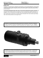
Hydraguide™
Service Procedure
Effective:
July 1, 2000
HGA Series Hydrostatic
Steering System
Service Manual
HGA Hydraguide™
Bulletin 2751-001-M1/USA
WARNING
FAILURE OR IMPROPER SELECTION OR IMPROPER USE OF THE PRODUCTS AND/OR SYSTEMS DESCRIBED HEREIN OR
RELATED ITEMS CAN CAUSE DEATH, PERSONAL INJURY AND PROPERTY DAMAGE.
This document and other information from Parker Hannifin Corporation, its subsidiaries and authorized distributors provide product and/or
system options for further investigation by users having technical expertise. It is important that you analyze all aspects of your application
and review the information concerning the product or system in the current product catalog. Due to the variety of operating conditions and
applications for these products or systems, the user, through its own analysis and testing, is solely responsible for making the final selection
of the products and systems and assuring that all performance, safety and warning requirements of the application are met.
The products described herein, including without limitation, product features, specifications, designs, availability and pricing, are subject to
change by Parker Hannifin Corporation and its subsidiaries at any time without notice.
Offer of Sale
The items described in this document are hereby offered for sale by Parker Hannifin Corporation, its subsidiaries or its authorized distributors.
This offer and its acceptance are governed by the provisions stated in the "Offer of Sale".
ã Copyright 2000, Parker Hannifin Corporation, All Rights Reserved
2
Hydraulics
Parker Hannifin Corporation
Hydraulic Pump/Motor Division
Greeneville, Tennessee
Bulletin 2751-001-M1/USA
Table of Contents
Service Manual
HGA Hydraguide™
Typical Oil Flow .................................................................................................................................................... 4
Hydraguide™ Steering
Model HGA ....................................................................................................................................................... 6
System Operation ............................................................................................................................................. 7
Design and Function ......................................................................................................................................... 7
Control Valve ..................................................................................................................................................... 8
Metering Section ............................................................................................................................................... 8
Rotor Operation ................................................................................................................................................ 8
Power Steering Operation ................................................................................................................................. 9
Manual Steering Operation ............................................................................................................................... 9
Exploded View .................................................................................................................................................... 10
Service Parts List ............................................................................................................................................... 11
Service Procedure .............................................................................................................................................. 13
Work Conditions .............................................................................................................................................. 13
Seal Replacement Instructions ....................................................................................................................... 14
Servicing of HGA Unit ..................................................................................................................................... 14
Disassembly Procedure ..................................................................................................................................... 15
Inspection and Replacement .............................................................................................................................. 18
Assembly Procedure .......................................................................................................................................... 19
HGA Column ...................................................................................................................................................... 23
Oil & Hydraulic Fluid
Filling and Air Bleeding System ...................................................................................................................... 24
Hydraulic Fluid ................................................................................................................................................ 24
Tips for Maintaining the System ......................................................................................................................... 25
Offer of Sale ....................................................................................................................................................... 26
3
Hydraulics
Parker Hannifin Corporation
Hydraulic Pump/Motor Division
Greeneville, Tennessee
Bulletin 2751-001-M1/USA
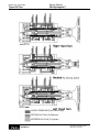
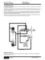
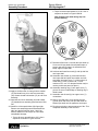
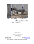
Typical Oil Flow
Service Manual
HGA Hydraguide™
SUPPLY PRESSURE (From Power Pump)
RETURN OIL FLOW (To Reservoir)
METERED OIL FLOW (To Cylinder)
4
Hydraulics
Parker Hannifin Corporation
Hydraulic Pump/Motor Division
Greeneville, Tennessee
Bulletin 2751-001-M1/USA
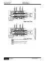
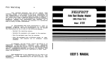
Typical Oil Flow
Service Manual
HGA Hydraguide™
OIL FLOW (From Recirculating Valve)
RETURN OIL (To Recirculating Valve)
METERED OIL FLOW (To Cylinder)
5
Hydraulics
Parker Hannifin Corporation
Hydraulic Pump/Motor Division
Greeneville, Tennessee
Bulletin 2751-001-M1/USA
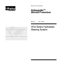
Hydraguide™ Steering
Service Manual
HGA Hydraguide™
MODEL HGA
Hydraguide™ is the name given to hydrostatic steering systems. In the HGA type Hydraguide™ steering system,
an engine-driven pump, relief valve, cylinder, reservoir, filter, fluid lines, and an HGA control unit are needed. An
automotive type steering wheel is attached to the HGA unit and the cylinder is connected by suitable means to
the steered wheels.
The driver has power steering control at all times, so long as system components work together, system integrity
is maintained, and adequate fluid is present. If there is a failure in the high-pressure circuit, a loss of power
steering will result. The HGA, however, is designed to have some manual steering capability, depending on the
installation. If you can’t manually steer the vehicle without using extraordinary measures, such as leaving your
seat, or pushing with your legs, don’t try it. Repair the failure in the power circuit. Some vehicles may be impossible to steer manually because of their weight and size.
WARNING: EXTRAORDINARY MEASURES SHOULD NOT BE USED IN ATTEMPTING TO MANUALLY
STEER THE VEHICLE, AS THEY MAY GENERATE FORCES IN EXCESS OF 125 FT. LBS., THEREBY
DAMAGING THE UNIT INTERNALLY, WHICH COULD RESULT IN A COMPLETE LOSS OF STEERING.
WARNING: ALL STEERING MECHANISMS ARE LIFE AND LIMB ITEMS. AS SUCH, IT IS IMPERATIVE
THAT THE INSTRUCTIONS IN THIS BOOKLET ARE FOLLOWED TO THE LETTER. FAILURE TO OBSERVE THE PROCEDURES SET OUT IN THIS PAMPHLET MAY RESULT IN LOSS OF STEERING.
6
Hydraulics
Parker Hannifin Corporation
Hydraulic Pump/Motor Division
Greeneville, Tennessee
Bulletin 2751-001-M1/USA
Hydraguide™ Steering
Service Manual
HGA Hydraguide™
SYSTEM OPERATION
This literature with the illustrations shown covers the basic design of the HGA unit. Variations may be engineered
to suit special requirements.
The description of the operation of the HGA unit and the illustrations explain the functioning of the system for the
utilization of the hydraulic power generated by the engine-driven pump for power steering. Emergency manual
operation is also described.
Satisfactory performance of this system requires a well engineered installation designed for the particular
type of vehicle and the type and kind of service for which it will be used. Parker Engineering advice and
assistance is available and we welcome requests.
Information on the required engine-driven pump capacity and the power cylinder size and connecting lines are
provided through engineering contacts. A balanced cylinder design is preferred.
Figure HGA-1
DESIGN & FUNCTION
The HGA unit consists of a fluid control valve section and a fluid metering section which are hydraulically and
mechanically inter-connected.
7
Hydraulics
Parker Hannifin Corporation
Hydraulic Pump/Motor Division
Greeneville, Tennessee
Service Manual
HGA Hydraguide™
Bulletin 2751-001-M1/USA
Hydraguide™ Steering
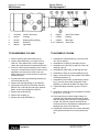
CONTROL VALVE
The control valve section contains a mechanically
actuated linear spool which is torsion bar centered.
The function of the control valve section is to direct fluid
to and from the metering section, and the cylinder, and
to regulate the pressure supplied to the cylinder. The
valve is provided with unique pressure chambers which
insure effective circuit isolation.
METERING SECTION
The metering section consists of a commutator and bidirectional gerotor element, which contains an orbiting
rotor and a fixed stator. The commutator rotates at orbit
speed with the rotor and channels the fluid to and from
the rotor set and the valve section.
The rotor incorporates unique sealing vanes which are
spring and hydraulically forced into sealing contact
between the rotor and stator to reduce leakage across
the metering section.
The function of the metering section is to meter the oil to
the power cylinder, maintaining the relationship between
the hand wheel and the steered wheels. An additional
function of the metering section is to act as a manually
operated pump providing manual steering in the event of
an inoperative engine-driven pump.
Figure HGA-2
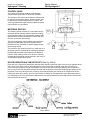
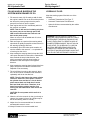
ROTOR OPERATION IN THE ROTOR SET (See Fig. HGA-3)
Each lobe of the rotor has a diametrically opposite lobe, therefore, when one lobe is in a cavity its opposite lobe is
at the crest of the stator’s convex form opposite the cavity. As the rotor is rotated, each lobe in sequence is
moved out of its cavity to the crest of the stator’s convex form and this forces each opposite lobe, in sequence,
into a cavity. Due to the interaction between the rotor and the stator, there are 42 fluid discharging actions in one
revolution of the rotor. When the rotor is moving, fluid is always flowing out of three of the cavities while fluid is
flowing into three other cavities, and one of the cavities is inactive as it changes from one of discharging fluid to
one of admitting fluid. The commutator rotates with the rotor and channels the fluid to and from the valve section,
and to and from the rotor set.
Figure HGA-3
8
Hydraulics
Parker Hannifin Corporation
Hydraulic Pump/Motor Division
Greeneville, Tennessee
Bulletin 2751-001-M1/USA
Hydraguide™ Steering
Service Manual
HGA Hydraguide™
commutator. The exhaust side of the rotor set is
connected, through the commutator, to one side of the
cylinder while the other side of the cylinder is connected to the reservoir. (See Figures HGA-1 and 2).
POWER STEERING OPERATION
When the spool is in center or neutral position, the
hydraulic oil from the engine-driven pump circulates
through the valve section, directly back to the reservoir
with sufficient pressure only to overcome friction of
valve channels and lines. There is no circulation of
engine-driven pump oil to or from the cylinder. Note
the center diagram showing neutral position (See
diagram on inside front cover) on which no directional
arrows appear in the metering channels. The oil
pressure at the two cylinder ports is equal and produces ineffective forces in the cylinder.
Further axial displacement of the spool results in
increased system pressure to provide the level of
pressure required. A portion or all of the hydraulic fluid
at the required pressure from the engine-driven pump,
depending upon the speed of steering, is directed to
the cylinder via the metering section, using cylinder
movement to accomplish the steering maneuver.
In order to accomplish a power steering maneuver, the
operator must rotate the steering wheel in the direction of the steering maneuver. The initial rotation of the
steering wheel rotates the input shaft which tends to
rotate the drive link and rotor set through the torsion
bar centering spring. Rotation of the rotor set and
spool which are coupled by the drive link, is resisted
by the cylinder pressure required to overcome the
steering forces. As the input shaft is rotated relative to
the spool, the centering spring is torsionally deflected.
Axial shift of the spool is induced by the ball which is
captive in the spool and engaged in the helical groove
provided in the input shaft.
MANUAL STEERING OPERATION
In the absence of system pressure, the driver's
manual effort displaces the spool axially. When the
spool is displaced within the body, fluid channels are
selected connecting the rotor set, which is now acting
as a pump, via the commutator to one side of the
cylinder. The return flow from the other side of the
cylinder is channeled through a recirculation valve so
that the oil will flow to the intake side of the rotor set
via the commutator instead of back to the reservoir.
(See. Figure HGA-5) The recirculation valve is a ball
check valve in a channel connecting the return flow
chamber to the engine-driven pump pressure inlet
chamber. The recirculation valve is closed during
power operation.
When the spool is axially displaced within the body,
fluid channels are selected connecting the enginedriven pump to the intake side of the rotor set via the
WARNING: ALL STEERING MECHANISMS ARE LIFE AND LIMB ITEMS. AS SUCH, IT IS IMPERATIVE
THAT THE INSTRUCTIONS IN THIS BOOKLET ARE FOLLOWED TO THE LETTER. FAILURE TO OBSERVE THE PROCEDURES SET OUT IN THIS PAMPHLET MAY RESULT IN LOSS OF STEERING.
9
Hydraulics
Parker Hannifin Corporation
Hydraulic Pump/Motor Division
Greeneville, Tennessee
32.
33.
34.
35.
36.
37.
38.
39.
Manifold
Commutator Ring
Commutator
Seal Retainer
Seal
Washer
End Cover
Special Bolt
Bulletin 2751-001-M1/USA
Hydraulics
Ball
“O” Ring
Plug
Spacer
Drive Link
Rotor Set
31 a. Stator
31 b. Rotor
31 c. Spring
31 d. Vane
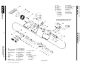
Exploded View
26.
27.
28.
29.
30.
31.
Vanes are specified on “HGA” units
with rotor widths smaller than 1.00.
Service Manual
HGA Hydraguide™
10
*
*
*
Parker Hannifin Corporation
Hydraulic Pump/Motor Division
Greeneville, Tennessee
1.
2.
3.
4.
5.
6.
7.
8.
9.
10.
Nut
Dirt & Water Seal
Retaining Ring
Backup Washer
Seal
Screw
Upper Cover
Seal
Shim
Retaining Ring
11.
12.
13.
14.
15.
16.
17.
18.
19.
20.
Thrust Washer
Thrust Bearing
Thrust Washer
Spring Washer
Spacer
Input Shaft
Needle Roller
Drive Ring
Spacer
Torsion Bar
(*Items 2, 4, 5 included in HG500007 Kit)
(**Items sold in matched sets only)
21.
22.
23.
24.
25.
Needle Roller
Spool
Ball
Spring
Housing Assembly
25 a. Plug
25 b. “O” Ring
25 c. Ball
Figure HGA-6
2, 4, & 5
3
6
7
8
9
10
11
Wheel
Nut
Seal
Kit*
Snap
Ring
Screw
(4 ea.)
Upper
Cover
Seal
Shim
Kit
Snap
Ring
Thrust
Washer
026045
HG500007
401233
021434 (Fine)
HGA016005X1
032840X1
033157X2
401367
400100
12
13
14
15
16A
16D
17
18
23
Thrust
Bearing
Thrust
Washer
Spring
Bearing
Spacer
Washer
Pinhole
Shaft
Straight
Spline
Needle
Roller
Drive
Ring
Ball
5/16” dia.
063979
400075
401366
477277
089181
089178
040114
HGA013003
400013
16C
16B
Wheel Mount Full Bolt
Shaft
Groove
089180
089193
24
25-A&B
25C & 26
27 & 28
29
32
33 & 34
37
38
Spring
Plug &
“O” Ring
Ball
1/4 dia.
Plug
Assy.
Spacer
Manifold
Commutator
Assy.
Washer
End Cover
401412
036147A1
G453570
415395A2
477235
HGA015001
HGA014000A1
028395
402803A1
Bulletin 2751-001-M1/USA
Hydraulics
1
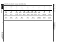
Service Parts List
USE WITH HGA SERVICE MANUAL EXPLODED VIEW
22 & 25 Housing & spool are non-serviceable due to select fit. If either needs to be replaced the housing assembly must be replaced.
Service Manual
HGA Hydraguide™
11
Parker Hannifin Corporation
Hydraulic Pump/Motor Division
Greeneville, Tennessee
Hydraulics
HGA
HGA
HGA
HGA
HGA
HGA
HGA
HGA
HGA
08
10
12
14
16
20
24
28
32
31
Length of
35
Length of
Vane Kit
Rotor Set
Rotor
Set
Seal
Retainer
Seal
Retainer
506607
506606
506611
506610
506609
———
———
———
———
HGA087010
HGA107010
HGA127007
HGA147005
HGA167005
HGA207005
HGA247005
HGA287005
HGA327004
.501
.626
.751
.876
1.001
1.252
1.502
1.752
2.002
099070
099071
099072
099073
099074
099075
099076
099077
099095
1.522
1.647
1.772
1.897
2.022
2.272
2.522
2.772
3.022
36
Length of
Rubber
Rubber
Boot Seal Boot Seal
032626
032618
032619
032627
032628
032620
032629
032621
032759
39
20 & 21
5/16-24 Thread
Torsion Bar**
Bolts (7 ea.)
Before Date
After Date
Code195-94 Code195-94
1.648
1.786
1.923
2.066
2.203
2.511
2.753
3.026
3.313
021269
021280
021283
021290
021292
021294
021295
021296
021349
021428
021356
021311
021306
021382
021357
021444
021358
021435
BASE-A10506
BASE-A10525
BASE-A10538
BASE-A10550
BASE-A10562
BASE-A10525
BASE-A10550
BASE-A10538
BASE-A10562
30
19
Drive Link
Spacer
HGA013008
HGA013008
HGA013008
HGA013008
HGA013008
HGA013005
HGA013005
HGA013006
HGA013006
4772480184
4772480196
4772480209
4772480221
4772480234
4772480196
4772480221
4772480209
4772480234
Bulletin 2751-001-M1/USA
Series
31C/D
Service Parts List
STANDARD PARTS THAT CHANGE WITH DISPLACEMENT
*Use part number 020206 on assemblies manufactured prior to date code 195-94
**Torsion bars are unit specific. To select the correct replacement, measure the diameter of the center section of the bar and the length between holes, then select
the correct base number from the following chart:
Bar Center Diameter - in.
0.147
0.160
0.160
0.154
0.147
0.139
0.139
Length Between Holes - in.
5.00 - 5.62
6.00 - 6.50
5.00 - 5.62
5.00 - 5.62
6.00 - 6.50
5.00 - 5.62
6.00
Service Manual
HGA Hydraguide™
12
Base Number
401360
401363
401368
401413
401432
401435
401627
Parker Hannifin Corporation
Hydraulic Pump/Motor Division
Greeneville, Tennessee
Service Manual
HGA Hydraguide™
Bulletin 2751-001-M1/USA
Service Procedure
SERVICE PROCEDURE
CLEAN WORK CONDITIONS
For service information on the steering pump (enginedriven) and power cylinder, see information provided
by the manufacturer of these units.
It is a must that the system be kept free of dirt or
foreign matter in the oil circuit. Cleanliness in servicing
this power steering system is absolutely necessary.
For servicing the HGA unit and the system, see
instructions in the following sections.
If it is necessary to disassemble any of the units, make
sure that a clean work bench or table is used. (A piece
of clean wrapping paper makes an excellent disposable top).
Servicing of HGA Unit
Page 14
Filling and Air Bleeding the System
When Drained of Oil
Page 24
Hydraulic Fluid
Page 24
Outside dirt should be cleaned off before disconnecting lines and port holes should be plugged immediately after disconnecting lines.
Finish cleaning off outside dirt before placing on work
bench.
When disassembled, parts should be cleaned only in
clear-clean petroleum base solvent and blown dry with
clean, dry air. Other solvents may cause deterioration
of rubber seals. Avoid wiping parts with cloth and
never steam clean hydraulic steering assemblies.
WARNING: SINCE SOLVENTS ARE FLAMMABLE, BE EXTREMELY CAREFUL WHEN USING THEM.
EVEN A SMALL EXPLOSION OR FIRE COULD CAUSE DEATH OR INJURY.
WARNING: EYE PROTECTION SHOULD BE WORN.
WARNING: OSHA MAXIMUM AIR PRESSURE REQUIREMENTS SHOULD BE COMPLIED WITH TO
PREVENT INJURY.
13
Hydraulics
Parker Hannifin Corporation
Hydraulic Pump/Motor Division
Greeneville, Tennessee
Bulletin 2751-001-M1/USA
Service Procedure
Service Manual
HGA Hydraguide™
SEAL REPLACEMENT INSTRUCTIONS
For numerous installation you may want to purchase the J26910 tool kit available from KENT MOORE TOOL
DIVISION, 29784 Little Mack, Roseville, Michigan 48066 - Phone (800) 345-2233.
Caution: Follow the instructions and do not disassemble the Hydraguide unit upper cover (7) to replace the shaft
seal (5).
1. Remove the steering wheel nut (1), steering wheel
and steering wheel column, if applicable. Refer to
page 18 for instructions on removal of steering
wheel column.
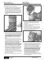
6. Cover the end of the Hydraguide unit input shaft
with cellophane tape to protect the new seal (5)
when it is assembled over the sharp edges of the
input shaft.
2. Remove the dirt seal (2) over the end of the
Hydraguide unit upper cover, if applicable. Discard
this part.
7. Lubricate the new seal using hydraulic oil and
install the new seal (5) with lip side first, onto the
Hydraguide unit input shaft.
3. Remove the retaining ring (3), do not discard, this
part must be reinstalled during assembly procedure.
8. Remove the cellophane tape from the Hydraguide
unit input shaft.
4. Remove the seal package parts (4) (5) from the
Hydraguide unit by one of the following methods:
9. Assemble the new washer (4), with small end first,
onto the Hydraguide unit input shaft and push the
new washer and the new seal (5), previously
installed, down into the Hydraguide unit upper
cover. (A short piece of metal tubing 15/16 minimum I.D. x 1-3/16 maximum O.D. or a 7/8 deep
well socket may be used to push these parts into
place.)
a) If the Hydraguide unit has not been removed
from the vehicle, rotate the Hydraguide unit
input shaft either clockwise or counter clockwise
to pressurize the system and force the seal
package out. Discard these parts.
b) If the Hydraguide unit has been removed from
the vehicle plug three of the four ports in the
Hydraguide unit and pressurize the other port
with air pressure to force the seal package out.
Discard these parts.
10. Assemble the previously used retaining ring (3)
onto the Hydraguide unit input shaft and down into
the Hydraguide unit upper cover groove. Be sure
the rounded edge of the retaining ring (3) is faced
inward.
5. Note: Clean the Hydraguide unit input shaft (16)
and upper cover (7) seal bore to remove particles
of dirt, felt, lint, etc. with a clean, lint-free rag.
Caution: excessive particles of felt or lint can cause
the new seal package to leak.
11. Assemble the new seal (2) onto the Hydraguide
unit input shaft and down into the Hydraguide unit
upper cover (7) counter bore.
12. Assemble the steering column, if applicable.
13. Assemble the steering wheel and wheel nut,
torque the wheel nut to 35 ft. lbs.
SERVICING OF HGA UNIT
Refer to exploded view, Figure HGA-6 for parts identification.
The spool (22) and the housing (25), the commutator (34), and commutator ring (33), as well as the rotor (31B)
and the stator (31A) are not separately replaceable because they are selectively fitted at the factory. If the spool
or housing need replacement, the complete housing assembly must be replaced. If the commutator or the
commutator ring need replacement, both must be replaced as a matched set. If the rotor or stator need replacement, the complete rotor set (31) must be replaced. The pin in the end cover is not separately replaceable. If the
pin or end cover need replacement, the end cover and pin assembly (38) must be replaced.
14
Hydraulics
Parker Hannifin Corporation
Hydraulic Pump/Motor Division
Greeneville, Tennessee
Bulletin 2751-001-M1/USA
Disassembly Procedure
Service Manual
HGA Hydraguide™
Plug the four port holes and clean the exterior of the
unit thoroughly. Then remove the plugs.
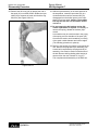
1. To prevent possible distortion or damage to unit if
placed directly in vise, the following procedure
should be used. Insert “o” ring tube fitting, with
tube nut or fitting cap attached, into one of the four
threaded ports in the housing. Clamp the fitting in
a vise in a manner which will locate the seven end
cover bolts in an upright position. (See Figure
HGA-7).
Figure HGA-8
fold (32), by a sliding and lifting motion. Care
should be used in the handling of this fragile
component.
7. Remove the manifold (32) from the rotor set (31)
by sliding and lifting motion.
8. Remove the rotor set (31), spacer (29) and drive
link (30) as an assembly by grasping the spacer
and removing the assembly with a sliding and
lifting motion. (See Figure HGA-9).
Figure HGA-7
2. Unscrew the seven special bolts (39) from the end
cover (38). Note: Special care should be used in
the following steps to insure protection of the
ground and lapped faces of the components.
Avoid scratching or nicking of finished surfaces.
3. Remove end cover (38) by bumping it sideways
with a soft hammer to loosen it from the rotor seal
(36) and seal retainer (35), and lift from unit.
Caution: The washer (37) and commutator (34)
may adhere to the end cover, and may be
removed with the end cover. Do not attempt to
remove pin because pin is press fit in the plate
and is non-serviceable. (See Figure HGA-8).
Figure HGA-9
9. Separate drive link (30) by sliding the rotor set (31)
on the spacer (29), allowing the drive link teeth to
clear the spacer hole. Remove drive link and
separate rotor set from spacer. Use extreme
caution to keep vanes (31D) and springs (31C)
from falling out. When handling the rotor set,
pressure should be applied to the rotor (31B)
by gripping the rotor set between the fingers
and urging the rotor into contact with the
stator (31A). (See Figure HGA-10)
4. Remove the rotor seal (36) and seal retainer (35)
by bumping the can sideways with a soft hammer
to loosen it from the housing and lift off the rotor
seal and seal retainer. Discard the rotor seal.
5. If the wear washer (37) and commutator (34) were
not removed with the end cover (38), remove these
parts from the HGA unit.
Carefully protect against damage to side faces.
Note: The rotor (31B) and the stator (31A) must be
kept in a matched set.
6. Remove the commutator ring (33) from the mani-
15
Hydraulics
Parker Hannifin Corporation
Hydraulic Pump/Motor Division
Greeneville, Tennessee
Bulletin 2751-001-M1/USA
Disassembly Procedure
Service Manual
HGA Hydraguide™
16. Remove seal (2), retaining ring (3), using proper
snap ring pliers. Discard seal (2). Remove and
discard backup washer (4). Remove and discard
seal (5).
17. Remove the retaining ring (10), thrust washer (11),
thrust bearing (12), thrust washer (13) and spring
washer (14) from input shaft (16). Note: Retaining
ring is twisted design. Do not straighten ring.
18. Remove the needle roller (17) by using a pin
punch of .125-inch max. diameter for a minimum of
.625 length. The input shaft (16) should be placed
on a block of wood (to avoid shaft damage) and
the needle roller (21) removed by impact, using
light hammer blows. (See Figure HGA-12).
Figure HGA-10
10. Reverse the HGA unit in the vise to place the input
shaft (16) in a vertical position. Using a center
punch, mark the upper cover flange (7) in relation
to a similar mark placed on the port face of the
housing (25) to facilitate reassembly. (See figure
HGA-11).
19. Remove the torsion bar (20) and spacer (19) by
inverting the spool assembly and allowing the
parts to fall free. Do not remove needle roller (21)
from torsion bar. (See Figure HGA-13).
MARKS
Figure HGA-11
11. Remove the four special cap screws (6) by using a
5/16-12 point socket.
Figure HGA-12
12. Grasp the input shaft (16) and with a smooth
upward motion, remove the input shaft (16), upper
cover (7) and spool (22) assembly from the
housing (25). Note: Avoid applying side forces
to the spool which would cause binding of the
closely fitted assembly. Never use excessive
force to remove the spool from the housing.
13. Remove and discard seal (8).
14. Remove the upper cover (7) with shaft seal package (Items 2 thru 5) intact. Remove spacer item
(15).
15. Remove shims (9) from either upper cover (7)
cavity or from face of thrust washer (11). Count
and record the number of shims to aid in reassembly of unit.
Figure HGA-13
16
Hydraulics
Parker Hannifin Corporation
Hydraulic Pump/Motor Division
Greeneville, Tennessee
Bulletin 2751-001-M1/USA
Disassembly Procedure
Service Manual
HGA Hydraguide™
20. Remove the drive ring (18) by placing the end of
the spool (22) on a table surface. Rotate the input
shaft (16) to extremes of travel until the drive ring
falls free. (See Figure HGA-14).
21. With the spool assembly in the same position as
the step above, rotate the input shaft (16) in a
clockwise direction until the actuator ball (23)
disengages from the helical groove in the input
shaft. Lift out input shaft. Caution: The actuator
ball may fall free and care should be used to
not lose it.
22. Do not remove the ball retainer spring (24)
unless replacement is required. If necessary to
remove this spring, discard the retainer (24) if
moved.
A screwdriver may be used to assist in the prying
of the spring over the shoulder of the spool (22).
Care must be used to avoid scratching or nicking
of the spool outside diameter and control edges.
(The following procedure is optional).
23. Return to the housing (25) which is mounted in the
vise. Remove the plug and roll pin assembly (28).
A steel ball is captivated by the plug and roll pin
assembly. Care must be used to avoid the loss of
the ball. Remove ball by shaking after housing is
removed from the vise. Discard “O” ring (27).
This completes the disassembly of the HGA unit.
Figure HGA-14
17
Hydraulics
Parker Hannifin Corporation
Hydraulic Pump/Motor Division
Greeneville, Tennessee
Bulletin 2751-001-M1/USA
Inspection and Replacement
Service Manual
HGA Hydraguide™
Visually inspect all parts and replace those parts
which are not in good condition. The following finished
surfaces should be inspected for abnormal wear,
scoring or damage.
Note: The rotor set (31) requires special attention
in handling to avoid nicks and scratching. It is
recommended that the rotor (31B), stator (31A),
vanes (31D) and springs (31C) be checked in the
assembled condition. To inspect the rotor set,
place the assembly face down on the lapped face
of the end cover (38) and check for freedom of
rotor rotation within the stator. The action of the
spring loaded vanes may be observed during
rotation. The vanes should move freely in their
slots, without bind, due to the forces of the
springs. (See Figure HGA-15).
1. Housing (25) bore and ends.
2. Valve spool (22) outside diameter. Some burnishing due to use may be observed.
3. Valve spool (22) control edges.
4. Valve spool (22) splines.
5. Input shaft (16) seal area. Check for rust, pitting
and excessive wear. Light circumferential polishing
due to seal contact may be observed.
6. Input shaft (16) helical groove. Note the contact
pattern created by the actuator ball (23). Surface
should be free from pits chipping or surface break
down.
7. Thrust bearing (12) and thrust washers (11) and
(13). Inspect for pitting of rolls and faces of thrust
washers.
8. Drive link (30) pin slot. Width of slot must not
exceed .001 inch difference at any point in its
length.
Figure HGA-15
9. Drive link (30) teeth.
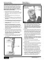
Using a feeler gage, check the rotor (31B) to the stator
(31A) clearance as shown in figure HGA-16. If there is
more than a .007 inch clearance, the rotor set (31)
must be replaced. Note: This applies to rotor sets
with and without vanes.
10. Torsion bar and needle roller assembly (20).
Difference in diameter of needle roller (21) should
not exceed .001.
The following parts may show a polish pattern due to
the rotor action and the circular motion of the commutator. The sides of these components are ground and
lapped and should be free from nicks, burrs and
scoring.
1. Spacer (29).
2. Manifold (32).
3. Rotor (31).
4. Commutator (34) and Commutator Ring (33).
Note: Thickness difference between commutator and commutator ring (33) shall not exceed
.002 inch.
5. End cover and pin assembly (38).
Figure HGA-16
Carefully lift the rotor set assembly (31) from the end
cover (38) and measure the thickness of the rotor
(31B) and stator (31A). Thickness difference between
the rotor and stator shall not exceed .003 inch.
The internal splines in the rotor should not allow
abnormal wear or damage.
18
Hydraulics
Parker Hannifin Corporation
Hydraulic Pump/Motor Division
Greeneville, Tennessee
Bulletin 2751-001-M1/USA
Assembly Procedure
Service Manual
HGA Hydraguide™
IMPORTANT; Before starting assembly, clean all
parts with clean petroleum base solvent and air
dry. Do not wipe dry with rags. Be sure all dried
paint chips have been removed from edges of
lapped surfaces. Unless otherwise indicated, DO
NOT oil parts before assembly.
1. Insert ball (26) into its cavity in the housing.
2. Install new “o” ring (27) on plug and roll-pin assembly (28) and install in the housing (25) to 10-14 ft.
lbs. torque.
3. Reclamp housing (25) in the vise as shown in
Figure HGA-11.
4. Assemble thrust washer (13), thrust bearing (12),
thrust washer (11) and retaining ring (10) on input
shaft (16).
5. If the retaining spring (24) has been removed, install
a new retaining spring. The spring must fit tightly.
6. Insert actuator ball (23) into ball seat located
inside spool (22).
Figure HGA-18
NOTE: Rotate the input shaft (16) out of the
valve spool (22) until input shaft will no longer
rotate. There will be a gap of approximately
.350 between end of valve spool (22) and thrust
washer (13) if the drive ring (18) is assembled
properly.
10. Insert the drive ring (18) into the spool (22) end by
visually aligning an internal space on the drive ring
with a tooth on the input shaft (16) split, and allow
the drive ring to drop to the limit of its travel. If the
drive ring does not engage the input shaft spline, a
slight rotation of the input shaft will allow the drive
ring to become fully engaged. Remove torsion bar
(20) gage. (See Figure HGA-18).
CAUTION: The HGA will not function properly if
the correct relationship of spool, drive ring and
input shaft is not achieved.
7. Assemble wave spring washer (14) over thrust
washer (13) and thrust bearing (12). Insert the
input shaft (16) into the spool, engaging the helix
and ball with a counter-clockwise motion. This
operation is best done while holding the spool in a
horizontal position.
8. Using the mid-section of the torsion bar (20) as a
gage, insert the gage between the spool end and
the thrust washer (13). (See Figure HGA-17). This
will position the spool in the necessary radial
relationship with the input shaft spline teeth for
assembly of drive ring (18).
9. Place the input shaft (16) and spool (22) assembly
in a vertical position, with the shaft end on the
table surface.
11. Install spacer (19) over torsion bar and pin
assembly (20) and insert the assembly into the
spool (22) end.
12. Align the cross-hole in the torsion bar (20) with the
cross-hole in the input shaft (16) and insert a .120
diameter pin punch to maintain alignment.
13. Insert the needle roller (17) into cross-hole in input
shaft (16); and while retracting the pin punch,
engage the pin in the torsion bar (20) cross-hole.
14. Initiate press of needle roller (17) into torsion bar
(20) with a few light impacts. Press needle roller
flush with outside diameter of input shaft (16) using
a 1/2” drive socket of 11/16 size for supporting the
input shaft. (See Figure HGA-19). With a few light
impacts on a .120 diameter pin punch, drive
needle roller (17) approximately 1/32 below the
input shaft (16) O.D. (See Figure HGA-12).
Figure HGA-17
19
Hydraulics
Parker Hannifin Corporation
Hydraulic Pump/Motor Division
Greeneville, Tennessee
Bulletin 2751-001-M1/USA
Assembly Procedure
Service Manual
HGA Hydraguide™
NOTE: If any of the input shaft (16), housing and
spool, torsion bar or upper cover (7) have been
replaced, the following procedure for checking and
shim adjustment must be used.
16b. Re-assemble as in “a” above using the required new
parts. After torquing the four screws (6) revolve unit in
vise so that the input shaft is pointing downward. In
order to determine that the unit is shimmed correctly,
the drive link (30) must be in its proper position. To do
this, grasp the input shaft (16), pull downward, and
prevent rotation. Engage drive link splines in spool (22)
and rotate to position spool essentially flush with end of
housing (25). Remove drive link and orient drive link
slot to engage torsion bar needle roller (21) and insert
drive link. Observe relationship of spool end to body.
The valve spool must protrude .020 ± .0025 from the
adjacent counterbore surface. If within spec. no
additional shimming required. If not within .0025, add or
remove shims (9) until this requirement is satisfied
repeating assembling steps as outlined in “a” above.
(See Figure HGA-21).
Figure HGA-19
15. Assemble spacer (15) over valve spool (22), against
spring washer (14). If so constructed, the inside lip end
of spacer must be toward the spring washer. Place
assembly, spool end first, into housing (25). Caution:
Avoid applying side forces to the spool which would
cause binding of the closely fitted assembly.
Note: If neither the input shaft (16) or upper cover (7)
are replaced, the original shims (9) may be reused.
However, if in the inspection of parts, damage is
found to the shims, discard these shims and replace
with new parts of equal thickness.
16a. Place shims on top of the thrust washer (11). Coat seal
(8) with clean grease and place in upper cover (7)
counterbore. Assemble upper cover onto input shaft (16)
and rotate to align punch marks previously made during
disassembly. Note: If a new upper cover is used no
angular orientation is required. However, it is
necessary to align the upper cover (7) and housing
(25). Replace with screws, finger tight, and then use a
pilot ring or a worm drive type hose clamp tightened
around the upper cover flange and the body pilot
diameter to achieve the required alignment. Now tighten
screws to 18-22 ft. lbs. torque. (See Figure HGA-20).
Figure HGA-21
16c. The correct shimming must be checked on the vehicle
or on a suitable hydraulic test stand. The amount of
steering effort required to steer the vehicle when the
vehicle is at rest on dry pavement must be equal within
three inch pounds. For example: if twenty-one inch
pounds is required to steer to the right, not less than
eighteen or more than twenty-four inch pounds should
be required to steer to the left.
If a test stand is available to place a load between
cylinder ports in the same manner as on the vehicle, a
test stand should be used. Add shims to increase
steering efforts in a left turn, subtract shims to
increase steering effort in a right turn.
17. With the drive link (30) installed as described above,
assemble two assembly posts into the housing (25) as
shown in Figure HGA-22. These assembly posts can be
made by simply cutting the heads off of two bolts similar
to the special bolts (39).
Figure HGA-20
20
Hydraulics
Parker Hannifin Corporation
Hydraulic Pump/Motor Division
Greeneville, Tennessee
Bulletin 2751-001-M1/USA
Assembly Procedure
Service Manual
HGA Hydraguide™
Figure HGA-22
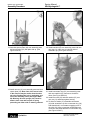
18. Assemble spacer plate (29) over assembly posts
and onto housing (25) with plain side up. (See
Figure HGA-23).
Figure HGA-24
20. Install manifold (32) over assembly posts and onto
rotor set (31), make sure circular slot side of
manifold is up. (See Figure HGA-25).
Figure HGA-23
Figure HGA-25
19. Install rotor set (31) over assembly posts and onto
spacer plate (29). Note: One of the seven holes
in the rotor set may be smaller than the other
six holes. Position this hole, if applicable, over
one of the assembly posts. (See Figure HGA24). Warning: All vane springs (31C) must be
down in their slots with no part of spring
protruding out either side of metering element.
21. Install commutator ring (33) over assembly posts
and onto manifold (32), make sure slot side is
down. (See Figure HGA-26).
22. Install rotor seal (36) and seal retainer (35) over
rotor set (31) and down against housing.
23. To allow for washer (37) assemble commutator
(34) with counterbore up into commutator ring (33)
with slotted hole in commutator engaging nose of
drive link (30). Align commutator outside diameter
concentric with inside diameter of commutator ring.
(See Figure HGA-27).
21
Hydraulics
Parker Hannifin Corporation
Hydraulic Pump/Motor Division
Greeneville, Tennessee
Bulletin 2751-001-M1/USA
Assembly Procedure
Service Manual
HGA Hydraguide™
2. Torque all seven special bolts to 15-19 ft. lbs. in
sequence as shown in Figure HGA-28.
Note: Rotate input shaft during step 2 to
prevent binding.
Figure HGA-26
Figure HGA-28
27. Relocate HGA unit in a vise with the input shaft up.
Cover end of input shaft with cellophane tape, to
protect new seal (5) when it is assembled over
sharp edges of input shaft.
28. Lubricate and install new seal (5) with lip side first
onto input shaft.
29. Assemble new washer (4), with small end first,
onto input shaft and push new washer and new
seal down into upper cover (7). (A short piece of
metal tubing, 15/16” minimum I.D. x 1-3/16”
maximum O.D. or a 7/8” deep well socket may be
used to push these parts into place.)
30. Assemble retaining ring (3) into upper cover (7)
groove. Be sure rounded edge of retaining ring is
faced inward.
Figure HGA-27
24. Apply a small amount of clean grease to washer
(37) and install over pin in end cover assembly
(38). Grease should hold washer (37) to end cover
assembly.
31. Assemble new dirt seal (2) into upper cover (7)
counterbore.
25. Assemble end cover assembly (38) with washer
(37) attached over assembly posts and onto HGA
unit.
32. Note: If the HGA unit is to be stored, plug the
cylinder ports and fill the inlet port with clean oil.
Rotate input shaft until oil appears at outlet port.
26. Install five of the special bolts (39) finger tight.
Remove two assembly posts and assemble the
other two special bolts per steps 1 and 2 as
follows, and do not over torque as it will cause
unrepairable damage:
33. Plug the port holes to prevent entrance of dirt. This
completes assembly of the HGA unit.
1. Torque all seven special bolts to 2-3 ft. lbs in
sequence as shown in Figure HGA-28.
22
Hydraulics
Parker Hannifin Corporation
Hydraulic Pump/Motor Division
Greeneville, Tennessee
Bulletin 2751-001-M1/USA
HGA Column
Service Manual
HGA Hydraguide™
1.
475109A1
Jacket Tube Clamp
6.
096245
Jacket Tube (Chart)
2.
403813
Coupling
7.
063980
Bushing
3.
401362
Retaining Ring (Spring)
8.
026045
Wheel Nut
4.
040050
Dowel Pin
6. & 7. 096245A1
5.
089142
Input Shaft
Jacket Tube
TO DISASSEMBLE COLUMN
TO ASSEMBLE COLUMN
1. Remove steering wheel and wheel nut (8).
1. Assemble the clamp assembly (1) onto the HGA
unit. (Do not tighten.)
2. Loosen clamp assembly (1) on upper cover of
HGA unit. If the system has a column support
clamp, this clamp should be loosened at this time.
2. Assemble the coupling (2) and align pin hole.
3. Assemble one of the pins (4) and one of the new
retaining rings (3).
3. If there is a horn contact assembly on the column,
remove the 4 small screws from the metal cover (if
applicable), and remove the metal cover and
gasket. Remove the 2 small screws from the horn
contact assembly.
4. Assemble the wheel tube (5) and align pin hole.
5. Assemble the other pin (4) and retaining ring (3).
6. Apply a small amount of clean grease to the inside
of bearing assembly (7).
4. Pull the jacket tube (6) and bearing assembly (7)
off of the wheel tube (5).
7. Assemble the jacket tube (6) and bearing assembly (7) over the wheel tube, through the clamp
assembly (1) and onto the HGA unit upper cover.
5. Remove the retaining springs (3) and discard.
6. Lightly tap out the pins (4) with brass rods and
hammer. Do not hit the pins with heavy hammer
blows, as this may damage the HGA unit.
8. Tighten the clamp assembly (1) bolt to 15-20 ft.
lbs.
9. Assemble the steering wheel and tighten the wheel
nut to 32.5 - 37.5 ft. lbs.
7. Remove the wheel tube (5).
8. Remove the coupling (2).
10. If the system has a column support clamp, it is
extremely important that the jacket tube (6) align
with this clamp in the free state. If misalignment is
evident, the HGA unit must be shimmed at the
mounting surface to eliminate the misalignment, or
damage may result to the HGA unit.
9. Remove the clamp assembly (1).
11. If applicable, assemble the horn contact assembly,
cover gasket and metal cover on the jacket tube
(6).
23
Hydraulics
Parker Hannifin Corporation
Hydraulic Pump/Motor Division
Greeneville, Tennessee
Bulletin 2751-001-M1/USA
Oil & Hydraulic Fluid
Service Manual
HGA Hydraguide™
FILLING AND AIR BLEEDING THE
SYSTEM WHEN DRAINED OF OIL
HYDRAULIC FLUID
Keep the steering system filled with one of the
following:
1. Fill reservoir nearly full. Be ready to add oil when
the engine is started. Do not let oil level drop below
the inlet to the power pump so that the power
pump will not suck air into the system.
2. Start engine and let it idle. Immediately add oil to
the reservoir as needed.
NOTE: This oil will now be circulating only from
the power pump to and through part of the
HGA control valve and to the reservoir and
back to the power pump.
•
Automatic Transmission Fluid Type “F”
•
Automatic Transmission Fluid Dexron II
•
Hydraulic fluid as recommended by the vehicle
manufacturer.
WARNING: DO NOT MIX OIL TYPES, ANY
MIXTURE, OR AN UNAPPROVED OIL, COULD
DETERIORATE THE SEALS. ENOUGH FLUID
COULD THEN LEAK TO CREATE A LOSS OF
POWER STEERING ASSIST. DO NOT ALLOW
FLUID LEVEL TO GO BELOW FILL LINE ON
DIPSTICK. BEFORE ADDING NEW FLUID,
COMPLETELY DRAIN OLD OIL FROM THE
SYSTEM. IT MAY BE NECESSARY ALSO THAT
YOU FLUSH THE SYSTEM WITH CLEAN OIL.
When no more oil can be added and oil is clear,
proceed as follows.
3. With one finger on a spoke of the steering wheel,
spin wheel as rapidly as possible to bleed the air in
the steering cylinder(s) and lines.
4. Immediately upon HGA valve spool actuation oil
must be added to the reservoir — to replenish the
oil moving into the circuit.
5. Keep rotating the steering wheel to keep the HGA
valve spool actuated. Do this until the road wheels
have reached the stop in that direction, then
quickly reverse the steering wheel rotation to
actuate the HGA valve spool in the opposite
direction.
6. Keep rotating the steering wheel left and right from
stop to stop of the road wheels to bleed out air.
Replenish oil as necessary.
7. The air will bleed out only at the reservoir, therefore, the oil must be circulated in both directions
repeatedly until the air has bled out.
NOTE: The oil in the lines to the power cylinder
reaches a “dead end” at the piston. The oil in
the cylinder does not flow in a circuit. As the
piston moves back and forth the oil moves
back and forth in the lines. Therefore, air in
these lines and the cylinder may be slow
moving into the HGA control valve and to the
reservoir.
CAUTION: Do not operate vehicle until air is
bled out.
8. When the oil in the reservoir is clear (not cloudy or
creamy), the system is free of air. (Slight creep or
drift of the steering wheel is normal.)
9. Adjust the oil to recommended level in reservoir
and assemble reservoir cover.
10. Always fill reservoir to recommended level.
24
Hydraulics
Parker Hannifin Corporation
Hydraulic Pump/Motor Division
Greeneville, Tennessee
Bulletin 2751-001-M1/USA
Tips
Service Manual
HGA Hydraguide™
TIPS FOR MAINTAINING THE HYDROSTATIC STEERING SYSTEM
•
Top off fluid level in reservoir as necessary.
•
Always use a puller to remove the steering wheel.
Do not use a hammer, torch, or crow bar.
Do not attempt to weld any broken steering
component. Replace the component with original
equipment only.
•
Maintain correctly inflated tires.
•
•
•
Investigate and correct immediately any play, rattle,
shimmy, or other unusual occurrence in the
steering system.
Do not cold straighten, hot straighten, or bend any
steering part.
•
•
Remove cause of steering column misalignment.
Prevent dirt or other foreign matter from entering
the hydraulic system. Clean off around filler caps
before checking oil level.
•
Encourage all drivers or operators to report any
malfunction or accident that may have damaged a
steering system part.
•
Investigate and correct any external leak in the
steering system, no matter how minor the leak.
•
Comply with manufacturer’s specifications for
cleaning or replacing the filter.
WARNINGS for Proper Steering System Operation
WARNING: DO NOT WELD, BRAZE, OR SOLDER ANY STEERING SYSTEM COMPONENT.
WARNING: MAXIMUM OPERATING PRESSURE MUST NOT EXCEED VEHICLE MANUFACTURER’S
RECOMMENDED PUMP PRESSURE CAPACITY.
WARNING: ALWAYS CAREFULLY INSPECT ANY STEERING SYSTEM COMPONENT THAT MAY HAVE
BEEN STRUCK OR DAMAGED DURING OPERATION OR IN AN ACCIDENT. REPLACE ANY COMPONENT THAT IS DAMAGED OR THAT IS QUESTIONABLE.
Parker extends close technical cooperation and assistance. If steering problems occur which you cannot
solve, please contact our Parker Field Service Department. Our phone number and address are on the
back cover of this manual.
25
Hydraulics
Parker Hannifin Corporation
Hydraulic Pump/Motor Division
Greeneville, Tennessee
Bulletin 2751-001-M1/USA
Service Manual
HGA Hydraguide™
Notes:
26
Hydraulics
Parker Hannifin Corporation
Hydraulic Pump/Motor Division
Greeneville, Tennessee
Bulletin 2751-001-M1/USA
Service Manual
HGA Hydraguide™
Notes:
27
Hydraulics
Parker Hannifin Corporation
Hydraulic Pump/Motor Division
Greeneville, Tennessee
Bulletin 2751-001-M1/USA
Service Manual
HGA Hydraguide™
Notes:
28
Hydraulics
Parker Hannifin Corporation
Hydraulic Pump/Motor Division
Greeneville, Tennessee
Bulletin 2751-001-M1/USA
Offer of Sale
Service Manual
HGA Hydraguide™
The items described in this document and other documents or descriptions provided by Parker Hannifin Corporation, its subsidiaries and its authorized
distributors are hereby offered for sale at prices to be established by Parker Hannifin Corporation, its subsidiaries and its authorized distributors. This
offer and its acceptance by any customer ("Buyer") shall be governed by all of the following Terms and Conditions. Buyer’s order for any such items,
when communicated to Parker Hannifin Corporation, its subsidiary or an authorized distributor ("Seller") verbally or in writing, shall constitute
acceptance of this offer.
1. Terms and Conditions of Sale: All descriptions, quotations, proposing any charges paid by Buyer. Unless otherwise agreed, Seller shall
als, offers, acknowledgments, acceptances and sales of Seller’s prodhave the right to alter, discard or otherwise dispose of any special tooling
ucts are subject to and shall be governed exclusively by the terms and
or other property in its sole discretion at any time.
conditions stated herein. Buyer’s acceptance of any offer to sell is
8. Buyer’s Property: Any designs, tools, patterns, materials, drawings,
limited to these terms and conditions. Any terms or conditions in addition
confidential information or equipment furnished by Buyer or any other
to, or inconsistent with those stated herein, proposed by Buyer in any
items which become Buyer’s property, may be considered obsolete and
acceptance of an offer by Seller, are hereby objected to. No such
may be destroyed by Seller after two (2) consecutive years have elapsed
additional, different or inconsistent terms and conditions shall become
without Buyer placing an order for the items which are manufactured
part of the contract between Buyer and Seller unless expressly acusing such property, Seller shall not be responsible for any loss or
cepted in writing by Seller. Seller’s acceptance of any offer to purchase
damage to such property while it is in Seller’s possession or control.
by Buyer is expressly conditional upon Buyer’s assent to all the terms
9. Taxes: Unless otherwise indicated on the face hereof, all prices and
and conditions stated herein, including any terms in addition to, or
charges are exclusive of excise, sales, use, property, occupational or like
inconsistent with those contained in Buyer’s offer, Acceptance of
taxes which may be imposed by any taxing authority upon the manufacSeller’s products shall in all events constitute such assent.
ture, sale or delivery of the items sold hereunder. If any such taxes must
2. Payment: Payment shall be made by Buyer net 30 days from the date
be paid by Seller or if Seller is liable for the collection of such tax, the
of delivery of the items purchased hereunder. Amounts not timely paid
amount thereof shall be in addition to the amounts for the items sold. Buyer
shall bear interest at the maximum rate permitted by law for each month
agrees to pay all such taxes or to reimburse Seller therefore upon receipt
or portion thereof that the Buyer is late in making payment. Any claims
of its invoice. If Buyer claims exemption from any sales, use or other tax
by Buyer for omissions or shortages in a shipment shall be waived
imposed by any taxing authority, Buyer shall save Seller harmless from
unless Seller receives notice thereof within 30 days after Buyer’s receipt
and against any such tax, together with any interest or penalties thereon
of the shipment.
which may be assessed if the items are held to be taxable.
3. Delivery: Unless otherwise provided on the face hereof, delivery
10. Indemnity For Infringement of Intellectual Property Rights:
shall be made F.O.B. Seller’s plant. Regardless of the method of
Seller shall have no liability for infringement of any patents, trademarks,
delivery, however, risk of loss shall pass to Buyer upon Seller’s delivery
copyrights, trade dress, trade secrets or similar rights except as provided
to a carrier. Any delivery dates shown are approximate only and Seller
in this Part 10. Seller will defend and indemnify Buyer against allegations
shall have no liability for any delays in delivery.
of infringement of U.S. Patents, U.S. Trademarks, copyrights, trade
4. Warranty: Seller warrants that the items sold hereunder shall be free
dress and trade secrets (hereinafter ‘Intellectual Property Rights’).
from defects in material or workmanship for a period of 18 months from
Seller will defend at its expense and will pay the cost of any settlement
date of shipment from Parker Hannifin Corporation. THIS WARRANTY
or damages awarded in an action brought against Buyer based on an
COMPRISES THE SOLE AND ENTIRE WARRANTY PERTAINING TO
allegation that an item sold pursuant to this contract infringes the
ITEMS PROVIDED HEREUNDER. SELLER MAKES NO OTHER WARIntellectual Property Rights of a third party. Seller’s obligation to defend
RANTY, GUARANTEE, OR REPRESENTATION OF ANY KIND WHATand indemnify Buyer is contingent on Buyer notifying Seller within ten
SOEVER. ALL OTHER WARRANTIES, INCLUDING BUT NOT LIM(10) days after Buyer becomes aware of such allegations of infringeITED TO, MERCHANTABILITY AND FITNESS FOR PURPOSE,
ment, and Seller having sole control over the defense of any allegations
WHETHER EXPRESS, IMPLIED, OR ARISING BY OPERATION OF
or actions including all negotiations for settlement or compromise. If an
LAW, TRADE USAGE, OR COURSE OF DEALING ARE HEREBY
item sold hereunder is subject to a claim that it infringes the Intellectual
DISCLAIMED. NOTWITHSTANDING THE FOREGOING, THERE ARE
Property Rights of a third party, Seller may, at its sole expense and
NO WARRANTIES WHATSOEVER ON ITEMS BUILT OR ACQUIRED
option, procure for Buyer the right to continue using said item, replace
WHOLLY OR PARTIALLY, TO BUYER’S DESIGNS OR SPECIFICAor modify said item so as to make it noninfringing, or offer to accept return
TIONS.
of said item and return the purchase price less a reasonable allowance
5. Limitation Of Remedy: SELLER’S LIABILITY ARISING FROM OR
for depreciation. Notwithstanding the foregoing, Seller shall have no
IN ANY WAY CONNECTED WITH THE ITEMS SOLD OR THIS CONliability for claims of infringement based on information provided by
TRACT SHALL BE LIMITED EXCLUSIVELY TO REPAIR OR REBuyer, or directed to items delivered hereunder for which the designs are
PLACEMENT OF THE ITEMS SOLD OR REFUND OF THE PURspecified in whole or part by Buyer, or infringements resulting from the
CHASE PRICE PAID BY BUYER, AT SELLER’S SOLE OPTION. IN NO
modification, combination or use in a system of any item sold hereunder.
EVENT SHALL SELLER BE LIABLE FOR ANY INCIDENTAL, CONThe foregoing provisions of this Part 10 shall constitute Seller’s sole and
SEQUENTIAL OR SPECIAL DAMAGES OF ANY KIND OR NATURE
exclusive liability and Buyer’s sole and exclusive remedy for infringeWHATSOEVER, INCLUDING BUT NOT LIMITED TO LOST PROFITS
ment of Intellectual Property Rights.
ARISING FROM OR IN ANY WAY CONNECTED WITH THIS AGREEIf a claim is based on information provided by Buyer or if the design for
MENT OR ITEMS SOLD HEREUNDER, WHETHER ALLEGED TO
an item delivered hereunder is specified in whole or in part by Buyer,
ARISE FROM BREACH OF CONTRACT, EXPRESS OR IMPLIED
Buyer shall defend and indemnify Seller for all costs, expenses or
WARRANTY, OR IN TORT, INCLUDING WITHOUT LIMITATION,
judgments resulting from any claim that such item infringes any patent,
NEGLIGENCE, FAILURE TO WARN OR STRICT LIABILITY.
trademark, copyright, trade dress, trade secret or any similar right.
6. Changes, Reschedules and Cancellations: Buyer may request to
11. Force Majeure: Seller does not assume the risk of and shall not be
modify the designs or specifications for the items sold hereunder as well
liable for delay or failure to perform any of Seller’s obligations by reason
as the quantities and delivery dates thereof, or may request to cancel all
of circumstances beyond the reasonable control of Seller (hereinafter
or part of this order, however, no such requested modification or
‘Events of Force Majeure’). Events of Force Majeure shall include
cancellation shall become part of the contract between Buyer and Seller
without limitation, accidents, acts of God, strikes or labor disputes, acts,
unless accepted by Seller in a written amendment to this Agreement.
laws, rules or regulations of any government or government agency,
Acceptance of any such requested modification or cancellation shall be
fires, floods, delays or failures in delivery of carriers or suppliers,
at Seller’s discretion, and shall be upon such terms and conditions as
shortages of materials and any other cause beyond Seller’s control.
Seller may require.
12. Entire Agreement/Governing Law: The terms and conditions set
7. Special Tooling: A tooling charge may be imposed for any special
forth herein, together with any amendments, modifications and any
tooling, including without limitation, dies, fixtures, molds and patterns,
different terms or conditions expressly accepted by Seller in writing,
acquired to manufacture items sold pursuant to this contract. Such
shall constitute the entire Agreement concerning the items sold, and
special tooling shall be and remain Seller’s property notwithstanding
there are no oral or other representations or agreements which
payment of any charges by Buyer. In no event will Buyer acquire any
pertain thereto. This Agreement shall be governed in all respects by
interest in apparatus belonging to Seller which is utilized in the manuthe law of the State of Ohio. No actions arising out of the sale of the
facture of the items sold hereunder, even if such apparatus has been
items sold hereunder or this Agreement may be brought by either
specially converted or adapted for such manufacture and notwithstandparty more than two (2) years after the cause of action accrues.
9/91-P
29
Hydraulics
Parker Hannifin Corporation
Hydraulic Pump/Motor Division
Greeneville, Tennessee
Hydraulics
Parker Hannifin Corporation
2745 Snapps Ferry Road
Greeneville, TN 37745 USA
Tel:
(423) 639-8151
FAX:
(423) 787-2418
Web site: http://www.parker.com
HGA 8/2000