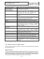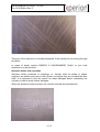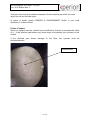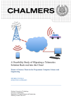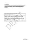
1
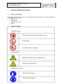
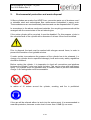
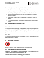
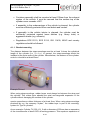
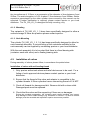
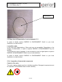
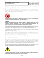
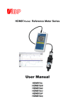
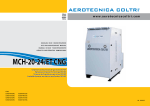
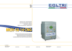
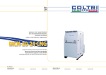
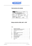
Service Manual
Pressure Cylinder
Type: TH_500
Variant: TH_500_HY_1
Variant: TH_500_HY_2
Variant: TH_500_HY_3
Variant: TH_500_HY_4
Variant: TH_500_HY_5
Manufactured by:
xperion Energy & Environment GmbH
Planckstraße 15
32052 Herford
Germany
1 / 21
Service Manual X-STORE “TH_500”
Oct. 2012 Edition Rev 2
TABLE OF CONTENTS
1.
General safety instructions ...........................................................................3
1.1 Relevant Standards --------------------------------------------------------------------- 3
In addition to this service manual, for the operation of CNG Systems, the following
standards must be taken into account:------------------------------------------------------ 3
• ECE R 110 ------------------------------------------------------------------------------------ 3
• ECE R 115 ------------------------------------------------------------------------------------ 3
• DIN EN ISO 11439-------------------------------------------------------------------------- 3
• NGV2 ------------------------------------------------------------------------------------------- 3
1.1. Sign description -------------------------------------------------------------------------- 3
2. Environmental protection and waste disposal ............................................4
3. Operating conditions .....................................................................................5
3.1. General-------------------------------------------------------------------------------------- 5
3.2. Gas composition -------------------------------------------------------------------------- 5
3.3. Temperature ranges --------------------------------------------------------------------- 6
3.4. Cylinder handling ------------------------------------------------------------------------- 6
3.5. Behaviour after an accident or fire --------------------------------------------------- 7
3.5.1.
3.5.2.
4.
Accident----------------------------------------------------------------------------------------- 7
Fire ----------------------------------------------------------------------------------------------- 7
Installation instructions .................................................................................7
4.1. Assembly of a cylinder into a vehicle------------------------------------------------ 7
4.1.1.
4.1.2.
4.1.3.
Bracket mounting ----------------------------------------------------------------------------- 8
Mounting---------------------------------------------------------------------------------------- 9
Neck Mounting -------------------------------------------------------------------------------- 9
4.2. Installation of valves --------------------------------------------------------------------- 9
4.3. Removal of valves and safety adapters ------------------------------------------ 12
5. Periodic Cylinder Inspection (“Gasanlagenprüfung” = GAP) according to
ECE R 110, ISO 11439, NGV2...................................................................13
5.1. Requirements for the auditor -------------------------------------------------------- 13
5.2. Procedure of the cylinder inspection ---------------------------------------------- 14
5.2.1.
5.2.2.
5.2.3.
5.2.4.
5.2.5.
Examination of documents ---------------------------------------------------------------- 14
Data of the label (example) --------------------------------------------------------------- 14
Optical control of the cylinder’s surface------------------------------------------------ 15
Inspection of connected components---------------------------------------------------- 18
Procedure of the leak test ------------------------------------------------------------------ 19
5.3. Checklist for the periodical inspection with X-Store cylinders -------------- 20
6. Approach at failure of a cylinder.................................................................21
7. Contact address ...........................................................................................21
2 / 21
Service Manual X-STORE “TH_500”
Oct. 2012 Edition Rev 2
1.
General safety instructions
1.1
Relevant Standards
In addition to this service manual, for the operation of CNG Systems, the following standards
must be taken into account:
• ECE R 110
• ECE R 115
• DIN EN ISO 11439
• NGV2
1.1.
Sign description
Prohibition signs
Work is allowed by authorized persons only
No smoking
Prohibition of fire and flames
Warning Signs
Warning of a danger point or safety note.
Warning of cold surfaces.
Commandment signs
Use protective gloves.
.
Use hearing protection
3 / 21
Service Manual X-STORE “TH_500”
Oct. 2012 Edition Rev 2
2.
Environmental protection and waste disposal
X-Store cylinders are made of an HDPE liner, connection parts out of aluminum and /
or stainless steel and carbon/glass fiber reinforcement embedded in epoxy resin.
These substances are environmentally harmless and can be disposed after 20 years.
In accordance to the above mentioned materials, the recycling processes should be
arranged with the current state of the art technologies.
If the entire cylinder will be recycled, it must be disabled. For this purpose, a hole in
the cylindrical wall of the cylinder with a diameter of at least 10mm must be drilled.
Prior to disposal, the tank must be washed with nitrogen several times, in order to
prevent the formation of an ignitable mixture.
If under certain circumstances the pressure of the cylinder has to be released, (i.e.
change of a cylinder due to superficial damage), local and country safety regulations
should be followed.
Before venting the cylinder, it is imperative to check all connections and pipelines
between the cylinder / valve and torch for leaks. This can be done with leak-detectspray. The cylinder must be grounded with a suitable cable to prevent electrostatic
charge. A fire extinguisher must be accessible.
In radius of 10 meters around the cylinder, smoking and fire is prohibited.
If the gas will be relieved without a torch into the environment, it is recommended to
wear ear-protection, because a noise level of more than 110dB (A) can occur.
4 / 21
Service Manual X-STORE “TH_500”
Oct. 2012 Edition Rev 2
In both cases it is important to note that the valve may cool down dramatically
through the effusion of the gas. Therefore gloves must be worn.
3.
Operating conditions
3.1. General
X-Store cylinders are designed for an operating pressure of 251MPa (250bar) at a
surrounding temperature of 15°C.
The cylinder may be filled only up to this pressure, with a working pressure of not
more than 25MPa (250bar) at a surrounding temperature of 15°C during the
adjustments of the resulting temperatures within the cylinder.
This corresponds under normal operating conditions to a maximum of 32.5MPa
(325bar). The maximum filling pressure should never exceed more than 32.5MPa
(325bar) at any temperature.
If the pressure is discharged for any reason and the cylinder should never be stored at
elevated temperature without pressure for longer than 3 month. If the cylinder is stored
for a longer period (more than 3 month), the cylinder must be pressurized up to p >
2,5bar. Pressurisation from ambient pressure (if the cylinder is completely empty) must
be carried out according to special procedure. Procedure can be provided by xperion.
The maximum useful life of the cylinder is 20 years in accordance with ECE R 110,
ISO 11439, NGV2 This lifetime of a cylinder is shown on every cylinder label (see
ECE R110 chapter 5.2.2), as well as in the documents of the cylinder.
During service, a periodical inspection according to chapter 5 must be carried out.
After the expiry of the useful life, the cylinder must be destroyed and disposed in
accordance with the instructions from chapter 2.
3.2. Gas composition
It must be ensured that the natural gas (CNG) corresponds with i.e. the ECE R 110
chapter 4.5 regulations, when filling the cylinders.
The operator of the filling stations is responsible for this.
Arid Gas:
1
Cylinder TH_500_HY_4 is designed for a operating pressure of 20MPa (200bar)
5 / 21
Service Manual X-STORE “TH_500”
Oct. 2012 Edition Rev 2
•
•
•
•
Water vapour content < 32mg/m3
Pressure dew point at 20MPa minimum -9°C
Hydrosulphide and other soluble sulphides < 23mg/m3
Oxygen < 1Vol.%
Humid Gas:
• Water vapour content > 32mg/m3
• Pressure dew point at 20MPa > -9°C
• Hydrosulphide and other soluble sulphides < 23mg/m3
• Oxygen < 1Vol.%
• Carbon dioxide < 4Vol.%
• Hydrogen < 0,1Vol.%
3.3. Temperature ranges
X-Store Cylinders are tested and homologated for a stabilized gas temperatures of
-40°C to +65°C.
Exceeding this temperature range is not permitted at any time. Even short time
exposure to temperatures > +65°C during any hot wor k (e.g. welding, thermal cutting,
etc.) close to the cylinder is forbidden. Furthermore the operator has to assure that
the cylinder does not come in contact with any sparks caused by hot works.
3.4. Cylinder handling
To avoid injuries to the hands through loose fibre ends, gloves must be worn at all
times.
Cylinders may never be lifted at the valves / adapters, because this might cause
damages not seen during visual inspection. Even minor forces can cause a
deformation of the electromagnetic device of the valve, which may cause a
malfunction of the automatic sealing device.
When dealing with composite pressure cylinders, it is particularly important to ensure
that no impact load (i.e. through falling cylinders) may occur.
To avoid abrasions at the cylinder’s surface, rubber layers must be used.
6 / 21
Service Manual X-STORE “TH_500”
Oct. 2012 Edition Rev 2
When storing cylinders, the following points have to be considered:
• The cylinders must be secured against rolling or sliding.
• If valves or adapters are screwed into the cylinder, the openings must be
closed with plastic plugs in order to eliminate the penetration of dirt particles.
• For long-term storage (more than one day), the cylinder must be protected
against UV-radiation.
•
Rubber layers should be used to avoid damage of the cylinder’s surface by
abrasion.
• It is not allowed to leave the cylinder without internal pressure fro more than 3
months
3.5. Behaviour after an accident or fire
3.5.1. Accident
If a cylinder has been involved in an accident and this incident resulted in a damage
of the cylinder, it must be tested by the company xperion or an authorized partner to
re-confirm its further suitability. It is important to provide all available documentation
of the accident (i.e. photos). Without such testing, it is prohibited to use the damaged
cylinder.
3.5.2. Fire
If a cylinder has been involved in an event of a fire, it must be decommissioned and
destroyed according to chapter 2.
4.
Installation instructions
All work on cylinders and gas equipment requires knowledgeable staff
4.1. Assembly of a cylinder into a vehicle
The service technician who is doing the assembly of the car with the CNG
Cylinders has to find out the best space in the car.
In special the following points have to be taken into account.
7 / 21
Service Manual X-STORE “TH_500”
Oct. 2012 Edition Rev 2
• Container assembly shall be mounted at least 100mm from the exhaust
system of the vehicle. It must be assured that the surface top of the
cylinder never exceeds +65°C.
• If assembly in the undercarriage of the vehicle is planned, the cylinder
must be sufficiently protected from road debris and contact.
• If assembly in the vehicle interior is planned, the cylinder must be
sufficiently protected against loose articles (e.g. heavy tools) or
aggressive media (e.g. solvents).
• Regulations ECE R110, ECE R115, ISO 11439, NGV2 and country
regulations should be followed.
4.1.1. Bracket mounting
The distance between the strap-mountings must be at least ½-times the cylindrical
length of the cylinder (Lx= ½ x L cyl). In general, the strap-mountings should be
installed at the outer ends of the cylinder. Nevertheless, the distance to the cylinderends Lend should be at least 50mm.
Lcyl
LX
Lend
Example Picture 1
When using strap-mountings, rubber layers must always be between the strap and
the cylinder. This rubber layer absorbs the axial and tangential expansion of the
cylinder without damaging the surface of the cylinder.
xperion prescribes a rubber thickness of at least 2mm. When using strap-mountings
produced by e.g. the company “Hydac”, the rubber layer is part of the mountingsystem for Type 4 cylinders.
As an example: Cylinder TH_500_HY_5 with a diameter of 500mm has an expansion
of the circumference of about 0.8% at working pressure. This equals an expansion of
8 / 21
Service Manual X-STORE “TH_500”
Oct. 2012 Edition Rev 2
the circumference of 12.5mm or an expansion of the diameter of 4mm between 0 and
250bar. The axial elongation is 0.5% or about 7.5mm between 0 and 250bar. Similar
expansion percentages for the other cylinder sizes covered by this manual can be
expected. If further clarification is required, please contact xperion or your local
distributor. The TH_500_HY_5 is designed for belly mounting, only.
4.1.2. Mounting
The variants of TH_500_HY_1, 3 have been specifically designed to allow a
vertical storage! If there are question please contact xperion.
4.1.3. Neck Mounting
The cylinder TH_500_HY_1, 2, 3, 4 has been specifically designed to allow for
neck mounted assembly. A current listing of the containers suitable for the
neck assembly can be supplied by contacting xperion or your local distributor.
With the neck assembly it is to be noted that there is a fixed bearing side
(container neck with valve) and a floating bearing side.
4.2. Installation of valves
During assembly of valves, please follow, in accordance the points below.
Installation of valves with self-sealing thread
1. Only xperion authorized valves and relief devices are to be used. For a
listing of such approved devices please contact xperion or your local
distributor.
2. Ensure that the thread of the valve and adapter is compatible to the
cylinder threads. X-Store cylinders have a connecting thread of 1/4 NPT.
3. Check all threads for damage and dirt. Remove dirt with a clean cloth.
Damaged parts must be replaced.
4. Check that the valve and the supporting if there are no damages.
During the complete preparation, the cylinders need careful handling. Any impact,
drop damage or other visible damage (e.g. scratches or notches t > 0.5mm or surface
damage) must be recorded and reported to xperion as soon as possible.
9 / 21
Service Manual X-STORE “TH_500”
Oct. 2012 Edition Rev 2
5. The transportation valve is sealed with PTFE tape. Manually (by hand) screw
the valve until it is firmly applied.
6. The adapter is mounted with 400Nm. Applying a torque > 400Nm to the
cylinder is not permitted. Tighten the valve with the matching specialty tool
with a torque of 130Nm. Applying a torque of 130Nm +/- 5Nm to the adapter /
cylinder is required.
Valve
Adapter
7. Mark the transition from valve to the cylinder with a drop of sealing mark/paint.
8. Record the change of the valve in the documents. During dismounting
processes the technician has to pay attention that no part of the PTFE tape
gets into the cylinder.
9. Test the system cylinder / adapter / valve / for leaks.
10 / 21
Service Manual X-STORE “TH_500”
Oct. 2012 Edition Rev 2
Installation of valves with o-rings sealing system
1. Only xperion authorized valves and relief devices are to be used. For a listing
of such approved devices please contact xperion or your local distributor.
2. Ensure that the thread of the valve and adapter is compatible to the cylinder
threads. X-Store cylinders have a connecting thread of 1.125-12UNF
3. Check all threads for damage and dirt. Remove dirt with a clean cloth.
Damaged parts must be replaced.
4. Check that the o-rings/supportrings and the o-ring groove has no damage. If
necessary replace the o-ring/supportring.
! Please note that the Support ring has two different sizes. The concave side is
orientated to the o-ring!
Add a small amount of Vaseline to the o-ring and support –ring.
During the complete preparation, the cylinders need careful handling. Any
impact, drop damage or other visible damage (e.g. scratches or notches t >
0.5mm or surface damage) must be recorded and reported to xperion as soon
as possible
5. Manually (by hand) screw the valve until it is firmly applied.
6. Tighten the valve with the matching specialty tool with a torque of 130 Nm.
Applying a torque > 130Nm to the cylinder is not permitted.
11 / 21
Service Manual X-STORE “TH_500”
Oct. 2012 Edition Rev 2
7. Mark the transition from valve to the cylinder with a drop of sealing mark/paint.
8. Record the change of the valve in the documents.
9. Test the system cylinder / adapter / valve / for leaks.
4.3. Removal of valves and safety adapters
It is important to ensure that the cylinder is depressurized.
should be followed.
The following steps
To do so, the manual valve must be closed.
Afterwards, the automatic sealing device must be opened by special adapter to
transfer the 12V. For any further instructions please contact xperion. The ear
protection must be worn, because the noise level through the out coming gas can
reach more than 110dB (A).
12 / 21
Service Manual X-STORE “TH_500”
Oct. 2012 Edition Rev 2
After the automatic sealing device has been opened, the manual valve must be
opened slowly. If CNG effuses, the cylinder is not completely empty. In this case,
please proceed as shown in chapter 2.
If you have to remove the valve from the cylinder please have a look into the
standard of ISO 11623:2002 (page 25).
For further instructions regarding the removal and service of the valve please refer to
the valve manufacturer instructions available by contacting xperion or your local
distributor.
5.
Periodic Cylinder Inspection (“Gasanlagenprüfung” = GAP)
according to ECE R 110, ISO 11439, NGV2
At regular intervals, however no longer than 48 months, cylinders for CNG use in
vehicles must be inspected. The test intervals are defined within the ECE-R110, ISO
11439 and NGV2 respectively within the regulations of each country.
During the inspection, the cylinder is examined whether any inadmissible damages
have occurred. Periodic inspections with water pressure tests and dismounting of the
cylinder are no longer necessary.
Every vehicle run with CNG must be undertaken a GAP. For example, in Germany,
the period between the last GAP and the next general vehicle inspection may never
be longer than 12 months. Due to the inspection interval of 24 months between the
general vehicle inspections of a passenger car, the maximum inspection interval
adds up to 36 months. The standard instructs that a visual inspection must be
performed every three years. Similar regulations apply accordingly in other countries.
National regulations should always be followed. If in doubt, please contact xperion or
your local distributor.
5.1. Requirements for the auditor
The auditor must be in possession of a certificate that he has been trained according
to the GAP or as required by National regulations. This GAP training instructs the
safety and technology regulations when dealing with pressure cylinders and other
CNG storage system components.
The GAP trainings are offered by various technical inspection authorities.
13 / 21
Service Manual X-STORE “TH_500”
Oct. 2012 Edition Rev 2
It is essential, that the auditor is in possession of this service manual in order to
ensure that important information is understood.
All work performed on the cylinders and components are only allowed by trained and
authorized staff only.
5.2.
Procedure of the cylinder inspection
5.2.1. Examination of documents
At first the cylinders data must be recorded and be compared with the data from the
logbooks (if applicable).
5.2.2. Data of the label (example)
Picture 2
14 / 21
Service Manual X-STORE “TH_500”
Oct. 2012 Edition Rev 2
NUR CNG/CNG ONLY
This cylinder is for compressed natural gas use only
xperion Energy &
Environment GmbH
Manufacturer of the cylinder
Do not use after
The maximum lifetime of a CNG cylinder. After
exceeding this date, the cylinder must be
decommissioned. Date is listed as MM / YYYY
ID number
ID number of cylinder. If applicable the version
number.
Serial number
Continuous serial number of the cylinder. ID number
and serial number together guarantee an explicit
allocation of the cylinder; nnnnn / YY
Volume
Empty weight
Working pressure
Nominal water volume in litre at ambient pressure
Weight of the cylinder without the valve in kg
Working pressure after temperature balancing.
Directly after the filling of the cylinder, the pressure
may exceed this pressure. For example: 25MPa =
250bar = 3626psi.
-40° to +65°C (-40°F to +149°F).
Permitted working
temperature
Test pressure
Date of first pressure test
Month / year of approval
Type approval
ECE type approval
According to
Pressure, which is applied on the cylinder at the
water-pressure-test in order to test the cylinder’s
strength. For example 37,5MPa = 375bar = 5438psi
Date on which the cylinder has first been tested and
approved by the TÜV. MM / YYYY
Date of approval through the certifying institute.
Number which has been allocated after the approval
by the certifying institute according to ISO11439.
Number which has been allocated after the approval
by the certifying institute according to ECE R 110.
This cylinder is approved according to DOT
FMVSS304/NGV2 – 07 by an independent cylinder
inspector
5.2.3. Optical control of the cylinder’s surface
X-Store cylinders are partly handmade. Therefore small optical differences between
the cylinders may occur.
Superficial cracks
The first pressure test during the manufacturing process of the cylinder may result in
uncritical inter fibre failure. These inter fibre failure are small harmless cracks in the
surface of the cylinder. The cracks usual occur in circumferential direction. When a
lot of resin accumulates at the surface, cracks may also occur in axial direction.
These cracks do not have an impact on the function of the cylinder.
15 / 21
Service Manual X-STORE “TH_500”
Oct. 2012 Edition Rev 2
This part of the inspection is considered passed, if the cracks are not running through
the fibres.
In cases of doubt, xperion ENERGY & ENVIRONMENT GmbH or your local
distributor is to be informed.
Abrasion marks and scratches
Abrasion marks, scratches or scrapings, i.e. through loose tie straps or rubber
supports, are without any harm to the cylinder, as long as they do not reach the fibre
itself. It is important to find the reason for these damages before reinstalling the
cylinder in order to avoid further damages.
When the scratches reach the fibre, the cylinder must be decommissioned.
16 / 21
Service Manual X-STORE “TH_500”
Oct. 2012 Edition Rev 2
This part of the test is considered as passed, if the scratches are within the resin
layer, but not the first fibre layer.
In cases of doubt, xperion ENERGY & ENVIRONMENT GmbH or your local
distributor is to be informed.
Points of impact
Shock or impacts onto the cylinder may be difficult to find and to evaluate the effect
of it. If the affected spot shows only small signs of scratches, the cylinders is still
usable.
If the affected spot shows damage to the fibre, the cylinder must be
decommissioned.
Delamination
17 / 21
Service Manual X-STORE “TH_500”
Oct. 2012 Edition Rev 2
Delamination
!!!!!!!Any kind of Delamination is not acceptable!!!!!!!!!
In cases of doubt, xperion ENERGY & ENVIRONMENT GmbH or your local
distributor is to be informed.
Loose fibre ends
Loose fibre and delamination of fibre ends are not acceptable. Depending on the
degree of delamination, a repair at xperion ENERGY & ENVIRONMENT may be
feasible.
To evaluate the level of damage, it may be helpful to send a digital photo to xperion
ENERGY & ENVIRONMENT GmbH or your local distributor.
In cases of doubt, xperion ENERGY & ENVIRONMENT GmbH or your local
distributor is to be informed.
5.2.4. Inspection of connected components
Control of the valve
The valve / piping adapter must be in faultless condition. Damaged components must
be replaced. The handwheel has to rotate smoothly.
18 / 21
Service Manual X-STORE “TH_500”
Oct. 2012 Edition Rev 2
Before unscrewing the valve or valve components, it must be ensured that the
cylinder is depressurised. See also chapter 4.3.
Please check that the glass bulb is completely intact at valves with a thermal
pressure release device. There should be no defects on such pressure release
devices. Damaged parts have to be replaced.
Before unscrewing the adapter or adapter components, it must be ensured that the
cylinder is completely depressurised. See also chapter 4.3.
Leak test
Xperion recommends using leak detection spray or soapsuds when leak testing
composite cylinders. Information of the testing by leak-measuring-machines (socalled sniffer devices) and leak rate tests can be provided by xperion.
The evaluation of the leak test must be done under the regulations of the ECE-R110.
Extract out of the 7th adjusted version from 3rd of February 2008, chapter 17.1.5:
“The system may not have permeable spots. That means that the system must be
bubble-free for three minutes.”
Please consider that small-sized bubbles may appear when using leak detection
spray. These bubbles must disappear after a few seconds. These bubbles have
nothing to do with permeation or leakage of the cylinder.
Should a cylinder or valve be permeable, a clear bubble growth can be detected.
5.2.5. Procedure of the leak test
The cylinder must be filled up to the appropriate working pressure. After filling, the
cylinder must rest for at least 2 hours in order to gain stable pressure and stable
temperature conditions. If the cylinder is heated due to the filling, the leak detecting
spray or the soapsuds may evaporate, which causes incorrect test results.
The complete cylinder should be leak tested. Especially the connection: valve /
cylinder / adapter must be tested, because these are the most critical joints.
If bubbles emerge within 3 minutes, the test has not passed. Leaking components
must now be replaced and the leak test carried out again.
19 / 21
Service Manual X-STORE “TH_500”
Oct. 2012 Edition Rev 2
5.3. Checklist for the periodical inspection with X-Store cylinders
1. Serial number of the cylinder:
_______________________________
2. Year and month of the initial approval:
_______________________________
3. Date of last inspection:
_______________________________
4. Executing company, name of auditor:
________ _______________________
5. Test criteria
5.1. Superficial cracks not deeper than up to the first fibre layer?
Yes ------- allowed
No ----- not allowed
5.2. Abrasion marks and scratches not deeper than up to the first fibre layer?
Yes ------- allowed
No ----- not allowed
5.3. Points of impact are not, or only to a small degree existent?
Yes ------- allowed
No ----- not allowed
5.4. Loose fibre ends are non existent?
Yes ------- allowed
No ----- not allowed
5.5. Valve and safety adapters are not damaged?
Yes ------- allowed
No ----- not allowed
5.6. The complete cylinder and attached components are without any leaks?
Yes ------- allowed
No ----- not allowed
_______________________________
Signature of authorized auditor
Each test criteria with "not allowed" errors causes the failure of the complete inspection. After
a possible repair, the complete checklist must be processed again. The inspection has only
been passed, if all cylinders positively tested.
20 / 21
Service Manual X-STORE “TH_500”
Oct. 2012 Edition Rev 2
6.
Approach at failure of a cylinder
xperion keeps record on all incidents which occur with X-Store cylinders.
If a cylinder fails during a pressure test, xperion must be informed. Please send the
serial number of the cylinder and the reason for failure to contact address from
chapter 7.
7.
Contact address
xperion Energy & Envrionment GmbH
Otto-Hahn-Straße 5
34123 Kassel
Germany
Phone:
Fax:
+49 (0)561 58549 -0
+49 (0)561 58549-29
[email protected]
www.xperion.de
21 / 21