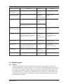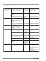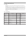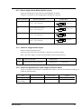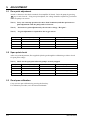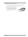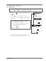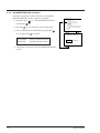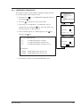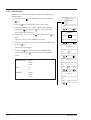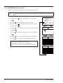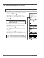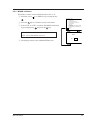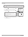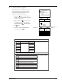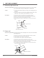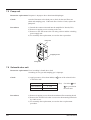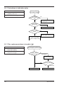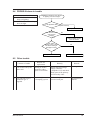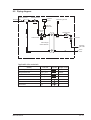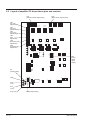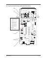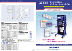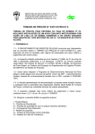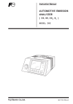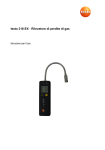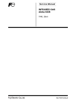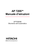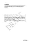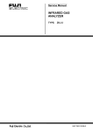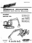
1
Service Manual AUTOMOTIVE EMISSION ANALYZER CO, HC, CO2, O2 Multiplex Analyzer Measuring Instrument TYPE: ZKE AUTOMO TIVE EMISSIO N ANALYIZER ▲ MODE ▲ SET ESC MEAS INZ-TN512524d-E CONTENTS INTRODUCTION ....................................................................................................... 1 1. PURPOSE OF USE .............................................................................................. 2 2. ITEMS ON DANGER AND WARNING ............................................................ 2 3. 4. 2.1 General safety precautions ..................................................................................... 2 2.2 Operating precautions ............................................................................................ 3 DESCRIPTION OF OPERATING PARTS AND CHECK ITEMS .................... 4 3.1 Sampling system .................................................................................................... 4 3.1.1 Outline ............................................................................................................... 4 3.1.2 Troubleshooting ............................................................................................. 4 3.2 Measuring unit ....................................................................................................... 5 3.2.1 Outline ........................................................................................................... 5 3.2.2 Troubleshooting ............................................................................................. 6 3.3 Electric system and PC board ................................................................................ 7 3.3.1 Outline ........................................................................................................... 7 3.3.2 Troubleshooting ............................................................................................. 7 VOLTAGE CHECK ............................................................................................. 8 4.1 5. 6. Voltage check of parts ........................................................................................... 8 4.1.1 Check for power supply voltage of amplifier PC board ................................ 8 4.1.2 Check for motor driven signal ....................................................................... 8 4.1.3 Check for pump driven signal (with pump driven) ....................................... 8 4.1.4 Sensor signal check (head amplifier output) ................................................. 9 4.1.5 Check for oxygen sensor signal ..................................................................... 9 4.1.6 Check and adjustment for power supply of main PC board .......................... 9 ADJUSTMENT .................................................................................................. 10 5.1 Zero point adjustment .......................................................................................... 10 5.2 Span point check .................................................................................................. 10 5.3 Zero/span calibration ........................................................................................... 10 5.4 Adjustment of pressure sensor voltage ................................................................ 11 PARAMETER MODE ....................................................................................... 12 6.1 Overview of each mode ....................................................................................... 12 6.2 How to set parameter mode ................................................................................. 12 6.3 Description of each mode .................................................................................... 13 6.3.1 DATA CLEAR ............................................................................................. 13 6.3.2 JAPANESE/ENGLISH indication ............................................................... 14 6.3.3 6.3.4 6.3.5 6.3.6 INZ-TN512524-E COMPONENT/RANGE SET ..................................................................... 15 PRITER SET ............................................................................................... 16 Zero OFFSET setting .................................................................................. 17 LINEARIZER table generation ................................................................... 18 i 6.3.7 6.3.8 6.3.9 6.3.10 6.3.11 7. 8. 9. ii INTERFERENCE COMPENSATION table generation ............................. 19 TEMPERATURE COMPENSATION table generation .............................. 20 MINUS indication ....................................................................................... 21 P.E.F ............................................................................................................. 22 Check of sensor signals ............................................................................... 23 UNIT REPLACEMENT..................................................................................... 24 7.1 Infrared ray light source unit ............................................................................... 24 7.2 Sensor unit ........................................................................................................... 24 7.3 Cell unit ............................................................................................................... 25 7.4 Switching power source unit ............................................................................... 25 7.5 Pump unit ............................................................................................................. 26 7.6 Solenoid valve unit .............................................................................................. 26 7.7 PC board unit ....................................................................................................... 27 7.8 Oxygen sensor unit (option) ................................................................................ 27 7.9 LCD fluorescent tube ........................................................................................... 28 TROUBLESHOOTING CHART ....................................................................... 29 8.1 Improper zero calibration .................................................................................... 29 8.2 Fluctuations in indication value ........................................................................... 30 8.3 8.4 Filter replacement alarm in trouble ( F ) ........................................................... 30 PROBE-IN alarm in trouble ................................................................................ 31 8.5 Other trouble ........................................................................................................ 31 ATTACHED DRAWINGS ........................................................................... A - 1 9.1 Wiring diagram ................................................................................................ A - 1 9.1.1 Wiring diagram (Manufacture before March, 2004) ............................... A - 1 9.1.2 Wiring diagram (Manufacture after April, 2004) .................................... A - 2 9.2 Piping diagram ................................................................................................. A - 3 9.3 Layout of amplifier PC board check pins and controls ................................... A - 4 9.4 Layout of main PC board check pins and controls .......................................... A - 5 INZ-TN512524-E INTRODUCTION You are now the owner of the automotive emission (carbon monoxide, hydrocarbon, carbon dioxide, oxygen) multiplex analyzer measuring instrument. Before using the instrument, be sure to read and understand the contents of this manual. The precautions and operating instructions should be observed to ensure the full performance of the unit and to prevent unexpected trouble such as electric shocks, accidents resulting in injury or death due to absorption of harmful gases. Manufacturer : Fuji Electric Instrumentation Co., Ltd. Type : Described in nameplate on main frame Date of manufacture : Described in nameplate on main frame Product nationality : Japan WARNING This instruction manual shows the following warning symbols on “danger”, “warning” and “caution” and their descriptions which are very important to ensure safe operation of the unit. Before using the unit, be sure to read and understand the description of the symbols to prevent accidents resulting in injury or death or damage to the unit. DANGER … … … Incorrect handling of the unit may lead to death or serious injury to the operator. WARNING … … … Incorrect handling of the unit may cause a risk of death or serious injury to the operator. CAUTION INZ-TN512524-E … … … Incorrect handling of the unit may lead to injury to the operator or damage to the unit. 1 1. PURPOSE OF USE This instrument is a multiplex analyzer capable of measuring 4 components in automotive emission; carbon monoxide (CO), hydrocarbon (HC), carbon dioxide (CO2) and oxygen (O2). 2. ITEMS ON DANGER AND WARNING 2.1 General safety precautions ① Before operating this instrument, read and understand the contents of this manual. ② Do not allow any person to use this instrument unless she/he is familiarized with the operation. ③ Preparation for operation, inspection and maintenance must be performed as mentioned in this manual. 2 INZ-TN512524-E 2.2 Operating precautions Failure to observe any of the following precautions could result not only in damage to the instrument but in personal injury or death. Be sure to read the following items and use the instrument correctly. DANGER GAS The span gas cotained in a can is harmful. Do not spray it to human body. • It may lead to a risk of death or serious injury. WARNING Be careful with electric shocks. • Turn OFF the power before performing wiring work to prevent risk of death or serious injury due to electric shocks. Before using the instrument , read and understand the contents of this instruction manual. • Incorrect handing of the instrument may lead to unexpected accidents. ??? Do not allow any person to use the instrument unless she/he is familiarized with the operation. • Incorrect handing of the instrument may lead to unexpected accidents. INZ-TN512524-E 3 3. DESCRIPTION OF OPERATING PARTS AND CHECK ITEMS 3.1 Sampling system 3.1.1 Outline The sampling system is used to supply a specified amount of automotive emissions to the measuring unit, by removing a trace of dust or drain from gases exhausted through the tail pipe of automobiles. For an analyzer to measure automotive emissions accurately, each unit of the sampling system must meet the following requirements. 1) Flow rate (monitored by pressure gauge) is as specified. 2) Air is not sucked into the units which are measuring automotive emissions. 3) It is designed not to allow dust or drain to enter the measuring unit. If these requirements are not met, the instrument may provide different measuring readings from actual concentration of emission gases. The following chart will help you locate the probable cause of trouble or perform the routine maintenance and check for the sampling system. 3.1.2 Troubleshooting Name of components Probe Phenomena Probable cause Flow rate is not supplied as specified. Clogged Indicating action is slow. Remedies • Replace. • Check for piping joints. Readings are too low due to absorbed Damaged air. Primary filter holder (with probe tightening screws) • Replace holder. Readings are too low due to absorbed Damaged Tightening screws • Retighten. air. are loose Sampling tube (with connecting cap) Flow rate is not supplied as specified Indicating action is slow. Clogged • Replace tube. • Check for piping joints. Readings are too low due to absorbed Damaged air. Primary filter element Flow rate is not supplied as specified. Dirty, clogged Indicating action is slow. Replace periodically. Membrane filter Flow rate is not supplied as specified. Dirty Indicating action is slow. Replace periodically. 4 INZ-TN512524-E Name of components Phenomena Probable cause Remedies O-ring (large, small) for membrane Readings are too low due to absorbed Damaged or air. scratched • Replace O-ring. Primary filter, drain separator and packing Readings are too low due to absorbed Damaged or air. scratched Incorrect fitting • Replace packing. • Check. Drain separator Readings are too low due to absorbed Damaged • Check. air. Fitting of connecting cap Flow rate is not supplied as specified Indicating action is slow. Clogged Membrane filter Readings are too low due to absorbed Damaged (for cover and cylinder) air. Closing of door • Replace O-ring. • Check. Double suction pump Gases are not suctioned. (Specified flow rate is not supplied.) Drain is not exhausted outside. Damaged diaphragm Disconnect exciting coil or burnout • Replace pump. • Check for pump signal (See Page 8). Pressure sensor Flow rate cannot be monitored. Improper sensor Improper circuit • Check for sensor. • Check for sensor circuit. Span gas inlet No readings of standard gases are not Clogged indicated since standard gases are not supplied to the measuring unit. • Internal piping • Check for connections. Internal piping Readings are too low due to absorbed Damaged, or improper plugging air. • Check for connections. Charcoal filter Response speed is too slow to return to zero point. Excessively clogged • Replace. 3.2 Measuring unit 3.2.1 Outline The measuring unit flows cleaned-up exhaust gases filtered by the sampling system into the internal sampling cell. It optically analyzes CO, HC and CO2 contained in the gases and converts them into electrical signal (voltage change). Use of solid state sensor and band pass filter makes the measuring unit compact, which is composed of infrared ray light source, cell (sampling cell only) and sensor unit. In addition, an O2 meter (option) uses galvanic cells. This section covers troubleshooting which aids you in finding out the causes of trouble and taking its remedy when the instrument is in trouble. INZ-TN512524-E 5 3.2.2 Troubleshooting Name of components Infrared ray light source unit Phenomena Readings remains unchanged. Probable cause Disconnected light source windings Readings are not stable due to lack of Dirty window sensitivity. Remedies • Measure winding resistance value (within 3.9Ω±30%). • Clean. Improper accuracy (linearity) of CO2 meter Sealing gas released • Replace light source unit. Readings are not stabilized due to lack of sensitivity, and zero calibration or span calibration is not carried out. Dirty sampling cell • Clean. Readings are not stabilized due to leak of sampling gas. Deteriorated O-ring • Replace. Cell holder Readings are not stabilized due to lack of sensitivity, and zero calibration or span calibration is not carried out. Dirty window • Clean. Sensor unit Readings are not stabilized. Dirty band pass filter (BPF) • Clean. Readings are not stabilized. Deteriorated or damaged sensor (head amplifier) • Replace. Readings remains unchanged. Improper motor revolutions • Check for motor signal (See Page 8). Readings remains unchanged. Sector revolution • Reinsert sector Temperature is not compensated properly. Disconnected temperature compensation resistance Oxygen meter readings are improper. Check oxygen sensor along for voltage. Cell unit Oxygen sensor 6 Disconnect the oxygen sensor connector and check the voltage. Zero gas (N2): 0 to 1mV Span gas (corresponding to 21%): 27mV±8mV INZ-TN512524-E 3.3 Electric system and PC board 3.3.1 Outline The electric system is used to operate the double suction pump motor fan and each PC board electrically. The PC board incorporates the first stage IC's of AC amplifier circuits of CO, HC and CO2 in the head amplifier (sensor unit). The amplifier PC board incorporates analog circuit, pump driven circuit, solenoid valve driven circuit and motor driven circuit for CO, HC and CO2 and O2. CPU and memory IC are mounted on the main printed board. Since the electrical system uses switching power for power supply, it is compact and lightweight. This section provides the troubleshooting which helps you to determine if each part is properly functioning. 3.3.2 Troubleshooting Phenomena Name of components Probable cause Remedies Power cord Electricity is not supplied to each unit. Disconnected • Replace. Tube fuse Electricity is not supplied to each unit. Disconnected • Replace. Fuse holder • Replace. Electricity is not supplied to each unit. Damaged or improper contact Power switch Electricity is not supplied to each unit. Improper contact • Replace. Switching power Electricity is not supplied to amplifier printed board. Faulty circuit Head amplifier See Pages 8 and 9. See Pages 8 and 9. Main printed board See Page 9. See Page 9. Amplifier printed board See Pages 8 and 9. INZ-TN512524-E • Replace. See Pages 8 and 9. 7 4. VOLTAGE CHECK 4.1 Voltage check of parts 4.1.1 Check for power supply voltage of amplifier PC board Attach a voltmeter across the check terminals of an amplifier PC board to check that the readings are within the standard range. Item Points to be checked Voltage check Power supply voltage Across Vcc and GND Power supply voltage Across P12 and SC +12.000V DC±0.5V Power supply voltage Across N12 and SC -12.000V DC±0.5V +5.000V DC±0.15V 4.1.2 Check for motor driven signal Attach an oscilloscope to the connector of the amplifier PC board to check for waveform. Item Motor driven signal Points to be checked Waveform check Across CN2 ① – ② terminals 24V± 5% 20ms±1% 4.1.3 Check for pump driven signal (with pump driven) Attach an oscilloscope to the connector of an amplifier PC board. Press MEAS key to check for waveforms when the pump is driven. Item Pump driving signal Points to be checked Waveform check Across CN3 ① – ② terminals 24V± 5% 20ms±1% 8 INZ-TN512524-E 4.1.4 Sensor signal check (Head amplifier output) Attach an oscilloscope to the connector of an amplifier PC board. Check for waveforms of each component by flowing zero gas (air). Item (component) CO Voltage check Points to be checked Across amplifier PC board, CN1 ⑤ - SC (check pin) AC 200mVp-p±50% 240ms±2% Across amplifier PC board, CN1 ④ -SC (check pin) HC AC 190mVp-p±50% 240ms±2% CO2 Across amplifier PC board, CN1 ⑥ - SC (check pin) AC 40mVp-p±50% 240ms±2% Ref AC 90mVp-p±50% Across amplifier PC board, CN1 ⑦ - SC (check pin) 240ms±2% 4.1.5 Check for oxygen sensor signal Remove CN8 from the PC board. Across the ends of the PC board, attach a voltmeter to check the voltage. Note) No power supply is required for the battery-powered oxygen sensor. Item O2 Points to be checked Voltage check Both terminals of sensor connector Zero gas (N2) Span gas (Air) : 0 to 1mV DC : 27±8mV DC 4.1.6 Check and adjustment for power supply of main PC board Attach a voltmeter across the check terminals of the main PC board to check that the readings are within the standard range. Item Points to be checked Power supply voltage Across VD-VG Indication power supply voltage Across TP6-GND INZ-TN512524-E Setting voltage +5.000V DC±0.2V +24.000V DC±0.2V Adjuster Check only VR1 9 5. ADJUSTMENT 5.1 Zero point adjustment Attach a voltmeter to the check terminals of an amplifier PC board. Drive the pump by pressing MEAS key to suck clean air. Using zero point adjuster, the voltage should be adjusted as given below when the pump is in suction. Note 1) Carry out warm-up operation (for more than 30 minutes) and then perform zero point adjustment while the pump sucks in clean air. Note 2) Perform zero point adjustment by the reference voltage, "Ref gain". Note 3) No gain adjustment is required for the oxygen sensor. Components Setting voltage Points to be checked Adjuster Ref - 2.000V DC±0.05V Across TP4 – SC VR4 CO 0.100V DC±0.1 V Across TP2 – SC VR2 HC 0.100V DC±0.1 V Across TP1 – SC VR1 CO2 0.200V DC±0.1 V Across TP3 – SC VR3 5.2 Span point check After zero point adjustment, flow supplied cylinder gas through the calibration gas inlet to check for span point voltage. Note 1) Check for the span point when the pump is securely stopped. Components Setting voltage Points to be checked Span gas Ref -2.000V DC±0.5V Across TP4 – SC CO +0.600V to +1.100 V DC Across TP2 – SC 3.0 to 3.5vol % CO HC +0.600V to +1.100 V DC Across TP1 – SC 3600 to 4000 volppm C3H8 CO2 +1.400V to +1.900 V DC Across TP3 – SC 18.0 to 20.0 vol % CO2 5.3 Zero/span calibration Carry out zero/span calibration by pressing the front key. For calibration procedure, refer to Instruction Manual. 10 INZ-TN512524-E 5.4 Adjustment of pressure sensor voltage ① Drive the pump by pressing MEAS key to suck in air through the drain port in about 15 sec. ② Attach a voltmeter across TP5 – SC of the amplifier PC board. Using VR6, adjust the voltage to 0.000V±0.1V (zero point adjustment for pressure sensor). ③ Cover the drain separator port with the palm of your hand so that airtightness can be maintained. Note) Press your hand tightly against the port. Otherwise airtightness may be impaired. MODE ▲ ④ Using VR5, adjust the voltage across TP5 - SC to 2.200V±0.1V. AUTOMOTIV EMISSION E ANALYIZER ▲ SET ESC MEAS Cover the port with the palm of your hand. INZ-TN512524-E 11 6. PARAMETER MODE To repair this instrument, the following data may have to be changed. 6.1 Overview of each mode Mode No. Name Contents 1 DATA CLEAR Initializes internal data (present parameter mode) 2 JAPANESE/ENGLISH indication Switches Japanese to English or vice versa. 3 COMPONENT/RANGE SET Sets the number of display components and HC range. 4 PRINTER SET Sets when a printer other than recommended one is connected. 5 OFFSET Sets hardware offset values. 6 LINEARIZER table generation Converts non-linear output into linear output. 7 INTERFERENCE COMPENSATION table generation Compensates for mutual interference. 8 TEMPERATURE COMPENSATION table generation Compensates for influence of ambient temperature. 9 MINUS indication Sets "with/without" of a minus indicator. 10 P.E.F entry Sets propane ratio coefficients at the time of HC span calibration. Alive signal values of each sensor Reads signals from sensors of CO/HC/CO2/O2/ temperature/pressure. 6.2 How to set parameter mode ① Select "8. PARAMETER SET" from the Menu screen. ② Press the SET key to set this mode , and the screen will be switched to this PARAMETER SET screen. ③ Using the digit select key key 1999-05-08 15:00 Cursor PARAMETER SET PASS WORD 0000 and value increment , enter the password. 1999-05-08 15:00 PARAMETER SET PASS WORD Type 6361 in the password box. ④ Press the SET 6361 key to display the PARAMETER SET MODE screen. 1999-05-08 15:00 PARAMETER MODE 1. DATA CLEAR 2. JAPANESE / ENGLISH 3. COMPONENT / RANGE SET 4. PRINTER SET 5. OFFSET 6. LINERIZER 7. INTERFERENCE COMPENSATION 8. TEMPERATURE COMPENSATION 9. MINUS 10. P.E.F 12 INZ-TN512524-E 6.3 Description of each mode 6.3.1 DATA CLEAR Note) Don't use this mode since it is used to clear internal data. If it must be used, keep records of information associated with all parameters. ① Point the cursor the 1999-05-08 15:00 to "1. DATA CLEAR" by pressing PARAMETER MODE 1. DATA CLEAR 2. JAPANESE / ENGLISH 3. COMPONENT / RANGE SET 4. PRINTER SET 5. OFFSET 6. LINERIZER 7. INTERFERENCE COMPENSATION 8. TEMPERATURE COMPENSATION 9. MINUS 10. P.E.F key. ② Press the SET key to switch the screen to this mode. ③ Select "YES" or "NO" by the key and press the SET key again. SET ESC 1999-05-08 15:00 DATA CLEAR No: The parameter screen will return without executing "DATA CLEAR". Yes: A message appears, prompting you to verify that you want to execute "Data Clear". OK: Press the SET key. YES NO NO YES SET ESC 1999-05-08 15:00 NO: Press the ESC key. DATA CLEAR OK SET ④ Whether pressing the "YES" or "NO" button or not, this screen will return to the "PARAMETER" screen. INZ-TN512524-E 13 6.3.2 JAPANESE/ENGLISH indication This mode is used to switch the indication of the MENU and PARAMETER screen to Japanese or English. ① Point the cursor key. pressing the ② Press the SET to "2. JAPANESE/ENGLISH" by key to switch the screen to this mode. ③ Select JAPANESE or ENGLISH by pressing the key, and press the SET key again. 1999-05-08 15:00 PARAMETER MODE 1. DATA CLEAR 2. JAPANESE / ENGLISH 3. COMPONENT / RANGE SET 4. PRINTER SET 5. OFFSET 6. LINERIZER 7. INTERFERENCE COMPENSATION 8. TEMPERATURE COMPENSATION 9. MINUS 10. P.E.F SET ESC 1999-05-08 15:00 JAPANESE / ENGLISH JAPANESE: Japanese indication mode ENGLISH: English indication mode JAPANESE ENGLISH SET ④ The display will return to the "PARAMETER MODE" screen. 14 INZ-TN512524-E 6.3.3 COMPONENT / RANGE SET This mode is used to set the number of display components and to select the range value of the HC meter. ① Point the cursor key. pressing the ② Press the SET to "3. COMPONENT/RANGE SET" by to switch the screen to this mode. key. Press the "SET" key. The cursor moves to "HC RANGE". ④ Select "10000volppm" or "14000volppm" by the and press the SET PARAMETER MODE 1. DATA CLEAR 2. JAPANESE / ENGLISH 3. COMPONENT / RANGE SET 4. PRINTER SET 5. OFFSET 6. LINERIZER 7. INTERFERENCE COMPENSATION 8. TEMPERATURE COMPENSATION 9. MINUS 10. P.E.F SET ③ Select any of "2-component", "3-component" and "4component" by pressing the 1999-05-08 15:00 1999-05-08 15:00 COMPONENT / RANGE SET COMPONENT key, ESC 2 3 4 HC RANGE 10000 14000 key. SET ESC 1999-05-08 15:00 NO. OF COMPONENTS COMPONENT / RANGE SET "2": 2-component display (CO/HC) "3": 3-component display (CO/HC/CO2) COMPONENT "4": 4-component display (CO/HC/CO2/O2) HC RANGE 10000 14000 2 3 4 SET HC RANGE "10000": 10000volppm meter in full scale "14000": 14000volppm meter in full scale ⑤ The display will return to the PARAMETER screen. INZ-TN512524-E 15 6.3.4 PRINTER SET This mode is used when selecting any printer other than recommended printer. 1999-05-08 15:00 ① Point the cursor PARAMETER MODE to "4. PRINTER SET" by pressing the 1. DATA CLEAR 2. JAPANESE / ENGLISH 3. COMPONENT / RANGE SET 4. PRINTER SET 5. OFFSET 6. LINERIZER 7. INTERFERENCE COMPENSATION 8. TEMPERATURE COMPENSATION 9. MINUS 10. P.E.F key. ② Press the SET key to switch the screen to this mode. ③ Select any of baud rates, "9600", "4800", and "2400" by pressing the , and press the SET SET key. The cursor will 1999-05-08 15:00 move to the "BIT" selection. ④ Select either "8" or "7" by the ESC PRINTER SET key, and press the SET key BAUDRATE 9600 4800 2400 again. BIT 8 The cursor moves to the "PARITY" selection. PARITY ⑤ Select any of "None", "Even" and "Odd" from PARITY and press the SET key. MODE NONE ODD ENEN SET ESC 1999-05-08 15:00 PRINTER SET The cursor will disappear. ⑥ Pressing the 7 key will return to the "PARAMETER" screen. Pressing the ESC key will return to the "PARITY" BAUDRATE 9600 4800 2400 BIT 8 PARITY 7 NONE ODD ENEN screen. SET ESC 1999-05-08 15:00 BAUD RATE: BIT: "9600" "4800" BAUDRATE 9600 4800 2400 "2400" BIT 8 "8" PARITY "7" PARITY: PRINTER SET "None" NONE ODD ENEN SET ESC 1999-05-08 15:00 PRINTER SET "Odd" "Even" 7 BAUDRATE BIT PARITY 9600 4800 2400 8 7 NONE ODD ENEN MODE 16 INZ-TN512524-E 6.3.5 Zero OFFSET setting This mode is used to offset zero electrically when replacing the main or amplifier PC board. ① Point the cursor to "5. OFFSET"" by 1999-05-08 15:00 . pressing the key ② Press the SET PARAMETER MODE 1. DATA CLEAR 2. JAPANESE / ENGLISH 3. O2 / RANGE SET 4. PRINTER SET 5. OFFSET 6. LINERIZER 7. INTERFERENCE COMPENSATION 8. TEMPERATURE COMPENSATION 9. MINUS 10. P.E.F key to switch the screen to this mode. ③ Use an adjuster on the amplifier PC board to adjust analog values of components to 0.1V±0.1V or less when the zero gas (N2) is supplied. (See Page 10). SET ESC 1999-05-08 15:00 OFFSET Digital counter value YES NO Note 1) Option O2 meter reads the counter indication, if provided. Note 2) Zero gas is permitted in the air, if the O2 meter is not provided. Note 3) The CO2 meter is used for internal compensation even when the 2-component mode is selected. This mode also is effective. CO HC CO2 O2 □ □ □ □ □ □ □ □ □ □ □ □ □ □ □ □ NO SET YES ESC When the "4-component display" mode is selected, the O2 meter is displayed. 1999-05-08 15:00 OFFSET YES NO CO HC CO2 O2 0 0 0 0 MODE ④ Select "YES" or "NO" from the OFFSET screen and press the SET key. NO: The OFFSET screen will return to the "PARAMETER" screen without executing "OFFSET". YES: It executes OFFSET. ⑤ Press the YES button again, and the cursor will disappear. The component counter indicates a value near 0. ⑥ Pressing the INZ-TN512524-E MODE key returns to the PARAMETER screen. 17 6.3.6 LINEARIZER table generation This mode is used when replacing the PC board and sensor unit. Note) If you have purchased sensor units for maintenance, supplied data is requested to enter. ① Point the cursor key to "6. LINEARIZER" by pressing the 1999-05-08 15:00 PARAMETER MODE 1. DATA CLEAR 2. JAPANESE / ENGLISH 3. COMPONENT / RANGE SET 4. PRINTER SET 5. OFFSET 6. LINERIZER 7. INTERFERENCE COMPENSATION 8. TEMPERATURE COMPENSATION 9. MINUS 10. P.E.F . ② Press the SET key to switch the screen to this mode. ③ Move the cursor by using the key to any component you want to change . SET ESC PARAMETER MODE ④ Press the SET by the key key to select the crossover you want to change LINERIZER TABLE . CO HC ⑤ Press the key SET key again to change each crossover data by the CO2 . SET ⑥ Press the ⑦ Press the SET key to save the data. The cursor will appear. ESC PARAMETER MODE LINEARIZER TABLE CO MODE key to return to the PARAMETER screen. No. of crossover points is 16 (1 to 16). X axis indicates output values or equivalent. X 1 2 3 4 5 6 7 8 Y 9 10 11 12 13 14 15 16 X SET Y axis indicates values of concentration or equivalent. Y ESC PARAMETER MODE LINEARIZER TABLE CO 1 2 3 4 5 6 7 8 X 0000 Y 9 10 11 12 13 14 15 16 X Y MODE 18 INZ-TN512524-E 6.3.7 INTERFERENCE COMPENSATION table generation This mode is used when replacing the PC board or sensor. Note) If you have purchased sensor units for maintenance, supplied data is requested to enter. ① Point the cursor to "7. INTERFERENCE COMPEN- SATION" by pressing the key ② Press the SET . key to switch the screen to this mode. ③ Move the cursor using the key to any datat you want to change by . 1999-05-08 15:00 PARAMETER MODE 1. DATA CLEAR 2. JAPANESE / ENGLISH 3. COMPONENT / RANGE SET 4. PRINTER SET 5. OFFSET 6. LINERIZER 7. INTERFERENCE COMPENSATION 8. TEMPERATURE COMPENSATION 9. MINUS 10. P.E.F SET ④ Press the SET key to select the crossover you want to ESC PARAMETER MODE INTERFERENCE change by the key . 1.CO←CO2 ⑤ Press the the key ⑥ Press the SET key again to change each crossover data by 2.CO←HC 3.HC←CO2 . SET ⑦ Pressing the key to save the data. The cursor will appear. MODE key returns to the PARAMETER screen. SET ESC PARAMETER MODE INTERFERENCE CO←HC CO2 CO CO2 SET CO ESC PARAMETER MODE INTERFERENCE CO←HC CO2 CO CO2 CO +00.01 MODE INZ-TN512524-E 19 6.3.8 TEMPERATURE COMPENSATION table generation This mode is used when replacing the PC board and sensor unit. Note) If you have purchased sensor units for maintenance, supplied data is requested to enter. ① Point the cursor to "8. TEMPERATURE COMPENSA. TION" by pressing the key ② Press the SET 1999-05-08 15:00 PARAMETER MODE 1. DATA CLEAR 2. JAPANESE / ENGLISH 3. COMPONENT / RANGE SET 4. PRINTER SET 5. OFFSET 6. LINERIZER 7. INTERFERENCE COMPENSATION 8. TEMPERATURE COMPENSATION 9. MINUS 10. P.E.F key to switch the screen to this mode. ③ Select either zero or span TEMPERATURE TABLE by the key . SET ESC PARAMETER MODE Note "TEMPERATURE TABLE is a collection of temperature sensor data. No change must be made for routine work. TEMP. COMP. TEMPERATURE TABLE ZERO TEMPERATURE TABLE SPAN TEMPERATURE TABLE ④ Press the SET key to select any component you want to change by using the key ⑤ Press the key SET . SET ESC PARAMETER MODE TEMP. COMP. ZERO. COMP. key again to change the Y-axis data by the CO . HC CO2 ⑥ After setting, press the ⑦ Pressing the MODE SET key to save the data. O2 SET key returns to the PARAMETER screen. ESC PARAMETER MODE TEMP. COMP. ZERO. COMP. X X axis: Temperature value (no change can be made) Y axis: Amount of compensation (change can be made) CO X Y 1 4 2 5 3 6 Y MODE 20 INZ-TN512524-E 6.3.9 MINUS indication This mode is used to set the indication below zero to "0". ① Point the cursor to "9. MINUS" by pressing the key . ② Press the 1999-05-08 15:00 PARAMETER MODE SET key to switch the screen to this mode. ③ Select "ON" or "OFF" to indicate the MINUS indication by pressing the key and press the SET key. 1. DATA CLEAR 2. JAPANESE / ENGLISH 3. COMPONENT / RANGE SET 4. PRINTER SET 5. OFFSET 6. LINERIZER 7. INTERFERENCE COMPENSATION 8. TEMPERATURE COMPENSATION 9. MINUS 10. P.E.F SET ON: indicates a value below zero. ESC 1999-05-08 15:00 MINUS OFF: sets a value below zero to 0. ON OFF ④ The display returns to the PARAMETER screen. SET INZ-TN512524-E 21 6.3.10 P.E.F This mode is used to set the range when replacing the PC board and sensor unit. Note) If you have purchased sensor units for maintenance, supplied data is requested to enter. ① Point the cursor to "10. P.E.F" by pressing the key . 1999-05-08 15:00 PARAMETER MODE ② Press the SET key to switch the screen to this mode. ③ Select the digit you want to change by using the key and set by the key , . 1. DATA CLEAR 2. JAPANESE / ENGLISH 3. COMPONENT / RANGE SET 4. PRINTER SET 5. OFFSET 6. LINERIZER 7. INTERFERENCE COMPENSATION 8. TEMPERATURE COMPENSATION 9. MINUS 10. P.E.F SET The setting range is from "0.300 to 0.700". When entering "0.000", the converted value becomes ✕ 1.000 or equivalent. If a value is entered beyond the range, the setting becomes invalid. ESC 1999-05-08 15:00 P. E. F P. E. F 0.500 SET ④ Press the SET key to save the data, then the display returns to the PARAMETER screen. 22 INZ-TN512524-E 6.3.11 Check of sensor signals The indication just after the A/D conversion of each sensor (CO/HC/CO2/O2/ temperature/pressure) can be read. It helps you in analyzing trouble. ① Press the MODE 1999-05-08 15:00 PARAMETER MODE 1. DATA CLEAR 2. JAPANESE / ENGLISH 3. COMPONENT / RANGE SET 4. PRINTER SET 5. OFFSET 6. LINERIZER 7. INTERFERENCE COMPENSATION 8. TEMPERATURE COMPENSATION 9. MINUS 10. P.E.F key on the PARAM- ETER screen. The pump is driven to switch to this mode. MODE ESC ② Move the cursor to select any of components you want to read by pressing the key the MODE analog input CO HC CO2 O2 and then press key. ③ To return to the PARAMETER screen, press the ESC Variables Variables Variables Variables SET ESC Component key. CO2 0.10vol% x0 x1 x2 x3 x4 x5 x6 x7 x8 x9 x10 x11 x12 x13 x14 x15 Concentration value Description of analog input AinP No. COUNT Sensor 0 Value just after HC 1 A/D conversion CO 2 CO2 12 O2 13 Temp. 14 Pressure * 3-11 and 15 are not used. CO / HC / CO2 / O2 / variables COUNT X INZ-TN512524-E 0 Value just after A/D conversion 1 Value after offset 2 Value after zero temperature compensation 3 Value after zero calibration 4 Value after interference compensation 5 Value after span temperature compensation 6 Value after span calibration 7 Value after linearization *X8 to X15 are not used. 23 7. UNIT REPLACEMENT 7.1 Infrared ray light source unit Reason for replacement: Disconnected or deteriorated infrared ray light source, leak of sealing gas, cracked window, improper readings due to contamination. Check : 1) Visually check that the window is not dirty or the sealing pipe is not damaged. 2) Detach the connector and check the winding resistance values of the light source. The resistance values should be 3.9Ω±30%. Procedures: 1) 2) 3) 4) Detach the connector inserted into the repeating connector. Remove 2-M4 screws which fix to the optical system base plate. Remove the cell unit from the light source holder. For assembly after repair or replacement, reverse the above procedure. Cell unit Light source unit 2-M4 screw Optical system base plate 7.2 Sensor unit Reason for replacement: Fluctuating indication due to damaged sensor, dirty and scratched B.P.F and damaged motor. Check: 1) Perform a visual check of window and B.P.F for stain or scratch. 2) Check that the sector rotates in a fixed cycle. 3) Check that the sensor signal is normal (See Page 9 ). Procedures: 1) 2) 3) 4) Detach the connector that is attached to the sensor unit. Remove 2-M4 screws which secure to the optical system base plate. Remove the cell unit from the light source holder. For assembly after repair or replacement, reverse the above procedures after repair or replacement. Cell unit Sensor unit Optical system base plate 2-M4 screw 24 INZ-TN512524-E 7.3 Cell unit Reason for replacement: Improper air tightness due to deteriorated O-ring. Poor sensitivity due to contaminated inner surface of the cell. Check: 1) Check that O-ring is free of crack or scratch. 2) Wipe the cell interior with a soft cloth. Procedure; Remove the infrared ray light source unit in Item 7.1 and sensor unit in Item 7.2 and then remove the cell unit. 7.4 Switching power source unit Reason for replacement: Indication lamp is not lit due to improper power supply voltage. Check: Check for power supply voltage of each unit. (See Page 8, 9.) Procedure: 1) Detach the primary and secondary connectors of switching power supply. 2) Remove claw that secures the case using a driver and the switching power supply unit. 3) For assembly after replacement, reverse the above replacement procedures. Fixing claw Secondary connector Switching power supply Primary connector INZ-TN512524-E 25 7.5 Pump unit Reason for replacement: Response is improper due to deteriorated diaphragm. Check: Attach a flowmeter to the drain port to check for the total flow rate (drain and sampling port). If the total flow is below 3l/min, replace the pump unit. Procedures: 1) Detach the connector inserted into the amplifier PC board (CN3). 2) Remove 2-tapping screws securing to the case. 3) Remove a claw that secures the case using a driver and the switching power supply unit. 4) For assembly after replacement, reverse the above procedure. Pump unit 2-tapping screw Fixing claw 7.6 Solenoid valve unit Reason for replacement: Error in reading is found due to leak. Switching of zero gas and sampling gas is improper. Check: 1) Apply pressure (of less than 20kPa) to A port of the solenoid valve to check for leak. Flow path direction Procedures: 26 Non-conductive A ⇔B Conductive A ⇔C Note) Gas inlets A and C are provided at the main unit. 1) Remove 4-tapping screws from the membrane filter mounting board. 2) Remove the solenoid valve that is secured to the mounting board unit by 2-M3 screws. 3) For assembly after replacement, reverse the above replacement procedure. INZ-TN512524-E 7.7 PC board unit Reason for replacement: It is damaged due to shorted power supply. Check: Check for voltage and waveform at each part. (For details, see Page 8 to 10.) Procedures: 1) 2) 3) 4) Detach the connector connected to each unit. Remove 2-tapping screws that secure the PC board. The amplifier is fixed to the main PC board by a single fixture (1). For assembly after replacement, reverse the above procedure. 7.8 Oxygen sensor unit Reason for replacement: This sensor unit is a consumable. Replacement should be performed every year. Check: Measure the voltage at both ends of the sensor connector. Voltage should be more than 10mV when sucking air. If not, replace it. Procedures: 1) Detach the connector inserted into the amplifier PC board (CN8). 2) Turn the oxygen sensor counterclockwise to remove from the mounting board. 3) Wind a seal tape on the replacement oxygen sensor and screw in clockwise. Oxygen sensor Mounting board INZ-TN512524-E 27 7.9 LCD fluorescent tube Reason for replacement: The fluorescent tube is a consumable. Replacement should be per formed every 10,000 hours. Procedures: 1) 2) 3) 4) 5) 6) Remove F.P.C cable from the main PC board (CN4). Remove 4-tapping screws which secure the front panel. The rear cover of the LCD panel is secured by claws at 5 positions. Remove the rear cover by using a driver. Lift both ends of the connecting lines for replacement. For assembly, reverse the replacement procedure. Connection line Rear cover claw LCD Fixing screw (4-taping screw) 28 Inverter PC board INZ-TN512524-E 8. TROUBLESHOOTING CHART 8.1 Improper zero calibration Zero calibration does not return to 0 Contents of errors ① After calibration, the “Component Does zero gas flow? Display” lamp flickers. No 1999-10-01 12:00 CO HC CO2 ② 9.00 0 0.05 Yes Flow zero gas voL% (see instruction manual). voLppm voL% No stains in optical system? No Yes Clean cell and window. Display is under bar or over bar Is connector attached properly? ____ 1999-10-01 12:00 CO HC _ _ _ _ CO2 0.05 No voL% Yes Take a remedy of faulty part. voLppm voL% Is each unit voltage proper? No (See Page 10) Yes Check and adjust Is the resistance value of light source proper? Yes Replace PC board INZ-TN512524-E No Replace the light source Perform zero and span calibrations again 29 8.2 Fluctuations in indication value ① ② Contents of trouble Concentration indication is suddenly scale-over. Fluctuations are sharpened. Measuring indications are suddenly changed. Is indication normal by flowing zero gas? Yes No Is motor-driven signal normal? Check again by flowing measuring gas. No (See Page 8) Yes Is motor revolution normal? (See Instruction Manual). Repair amplifier and main PCB. No (See Page 8) Yes Replace motor. Repair amplifier and main PCB. It seems that optical system is in trouble. See chapter 4 to check for voltage in each unit. 8.3 Filter replacement alarm in trouble ( ① ② Contents of trouble Filter replacement indication lamp keeps lighting. Filter replacement indication lamp does not light. F ) Filter replacement indication lamp keeps on lighting or does not light. Is pressure sensor voltage normal? No (See Page11). Yes Adjust pressure sensor voltage. Yes Is air-tightness OK? No Replace pressure sensor. 30 (See Manual). Take a step of parts in trouble. INZ-TN512524-E 8.4 PROBE-IN alarm in trouble ① ② Contents of trouble PROBE-IN indication lamp keeps on lighting. PROBE-IN indication lamp does not light. PROBE-IN indication lamp keeps on lighting or does not light. Is air-tightness OK? No (See manual). Yes Repair parts in trouble. Do CO2 meter and HC meter read normal voltage? No (See Page 10) Yes Adjust voltage of CO2 and HC meters. CO2 meter reading 4vol% or less? HC meter reading of 20volppm or less? No Yes Replace sensor unit. Perform zero calibration. 8.5 Other trouble Contents of touble Reasons for replacement Remedy Remark ① Fuse is burn-out by the power ON. Wiring or PCB is shorted or other parts are in trouble. Detach the PCB voltage supply connector (Amplifier CN7) and check faulty parts of the primary and secondary sides. See Page 10. ② Gas will leak even if calibration gas is supplied. Poor air-tightness of sampling system. Perform airtightness check of each part. See Instruction Manual. INZ-TN512524-E 31 Solenoid valve P GND +12V + CN1 8 76 543 21 Head amplifier PC board -12V GND2 +12V +5V GND1 + – O2 + B W Y G R : : : : : (Printer) CN5 Black White Yellow Green Red (Output) CN10 Amplifier PC board CN4 1(SV) (O2 sensor) 2 CN8 3 43 21 1 CN3 2(Pump) 8 76 543 21 21 543 21 CN2 CN1 CN7 (Motor) (Head amplifier) (Power supply) – M Motor Temperature detector resistance 1 2 V1 V3 G2 V2 G1 W G/ W G R/W R B/W B +12V GND Fluorescent ray light source Repeating connector 1 2 AC INPUT Y/W DC pump L N FG Connected to the fixing screw on the light source side Twisted pair wire Connected to the fixing screw on the sensor block side P N E Switching power – F + B1 A1 43 21 CN11 (Inverter) B32 A32 CN9 (Main) Pink White – CN2 (OUT) (IN) CN1 21 Inverter B1 A1 Main PC board 12 11 10 9 8 7 6 5 4 3 2 1 CN4 (Liquid crystal) F.P.C 12 11 10 9 8 7 6 5 4 3 2 1 CN3 (Amplifier) B32 A32 Liquid crystal (GMF32024HB) Black Purple Yellow Brawn Red Color of wiring FLM CL1 CL2 Vdd Vss D.off D3 D2 D1 D0 Vee Vo INZ-TN512524-E Sheet key Blue White Green Orange 10 9 8 7 6 5 4 3 2 1 CN3 (Sheet key) F.P.C 20 18 16 14 12 10 8 6 4 2 19 17 15 13 11 9 7 5 3 1 GND Key8 Key7 Key6 Key5 Key4 Key3 Key2 Key1 Vcc Power supply socket unit Fan 9. ATTACHED DRAWINGS 9.1 Wiring diagram 9.1.1 Wiring diagram (Manufacture before March, 2004) A-1 P GND +12V +12V GND 1 2 + CN1 8 76 543 21 Head amplifier PC board – O2 + : : : : : (Output) CN10 B W Y G R + Black White Yellow Green Red (Printer) CN5 543 21 CN7 (Power supply) Amplifier PC board 8 76 543 21 CN1 (Head amplifier) CN4 1 (SV) (O2 sensor) 2 CN8 3 43 21 1 CN3 2 (Pump) 21 CN2 (Motor) – M Motor Temperature detector resistance 1 2 +12V V2 4 G1 5 GND1 V1 6 +5V CN2 -12V V3 1 2 G2 3 GND2 W G/ W G R/W R B/W B DC pump Fluorescent ray light source Repeating connector CN1 5 3 1 Y/W Solenoid valve FG L N Connected to the fixing screw on the light source side Twisted pair wire Connected to the fixing screw on the sensor block side P N E Switching power – F CN9 (Main) B1 A1 43 21 CN11 (Inverter) B32 A32 + Pink White – CN2 (OUT) (IN) CN1 21 Inverter B1 A1 Main PC board 12 11 10 9 8 7 6 5 4 3 2 1 CN4 (Liquid crystal) F.P.C 12 11 10 9 8 7 6 5 4 3 2 1 CN3 (Amplifier) B32 A32 Liquid crystal (GMF32024HB) Black Purple Yellow Brawn Red Color of wiring FLM CL1 CL2 Vdd Vss D.off D3 D2 D1 D0 Vee Vo A-2 Sheet key Blue White Green Orange 10 9 8 7 6 5 4 3 2 1 CN3 (Sheet key) F.P.C 20 18 16 14 12 10 8 6 4 2 19 17 15 13 11 9 7 5 3 1 GND Key8 Key7 Key6 Key5 Key4 Key3 Key2 Key1 Vcc Power supply socket unit Fan 9.1.2 Wiring diagram (Manufacture after April, 2004) INZ-TN512524-E 9.2 Piping diagram Drain separator Measured gas Membrane filter Pressure sensor M Calibration gas inlet Tube with different dia Solenoid valve B A C Charcoal filter Sampling cell P Cheese valve Cheese valve O.P O2 sensor Solenoid type double absorber Sampling gas outlet Drain outlet P Applicable tube materials Quality Tube dia. Symbol Length of use Soft transparent vinyl tube φ4.8/φ2.8 150mm Polyurethane tube φ9/φ5.5 500mm Toaron tube φ9/φ5 500mm Toaron tube φ7/φ4 200mm Hose band φ8 4 Hose band φ4.3 2 Hose band φ7 1 INZ-TN512524-E A-3 VCC (+5V) P12(+12V) A-4 K D15 C81 R97 C70 C71 R98 A C76 R96 R95 R88 A K D10 D9 R94 R93 R92 C75 C78 K A A K D12 D11 R89 R90 R91 C77 C68 K A 4 6 1 R78 C80 R81 R79 R82 R68 R66 R67 R64 R65 CN3 2 SEN1 R77 TP3 3 1 R53 R52 R49 R40 R39 R36 R35 R26 R25 R22 R21 R12 R76R11 R83 R8 R7 R84 TP4 R50 R37 R38 R23 R24 R9 R10 VR6 R51 R41 R34 TMP6 R42 R27 R20 TMP4 R28 R13 R6 TMP2 R14 TP1 R48 C43 C41 C39 TP2 C37 D4 D3 D2 R55 R54 R56 3 3 3 3 D1 VR5 1 2 1 2 1 2 1 2 VR4 R3 C3 R2 R102 C24 R44 R101 C17 R30 R100 C10 R16 VR3 VR2 R43 R45 4 1 3 1 1 2 C2 3 R31 C16 R29 R17 C9 R15 8 R99 C2 R1 VR1 1 CN11 CN4 CN2 CN1 CN1 (CO/HC/CO2/Ref signal input) C72 C53 C52 C51 C64 R75 TP5 VR6 (Pressure zero adjustment) Q14 C62 CN7 5 VR5 (Pressure span adjustment) C80 GND CN8 1 VR4 (Ref adjustment) R61 R104 4 VR2 (CO zero adjustment) VR3 (CO2 zero adjustment) Q16 SC SC (Analog GND) R103 C79 1 VR1 (HC zero adjustment) P12 N12 VCC GND1 9.3 Layout of amplifier PC board check pins and controls CN2 (Motor driven signal output) CN3 (Pump driven signal output) N12 (-12V) CN8(O2 signal input) INZ-TN512524-E CN1 10 1 1 12 14 CN5 20 C113 C114 80 C115 CN4 C116 81 C117 1 51 50 C121 C118 C119 C120 + Q5 Q6 07 S01 C143 1 30 C36 100 31 24 1 L100 Q15 RN1 Q13 Q14 G 1 R4 Q32 5 4 E 1 T4 C R132 8 Q31 RN2 25 48 Q2 R110 R111 Q27 C16 + RN3 Q4 C47 + + + S02 C49 GND C144 Q12 Q3 L101 VR2 X2 56 29 Q6 + + T11 C6 R115 Q9 57 1 4 + 2 X1 3 Q1 + R113 R114 + C12 28 6 5 Q30 C48 C50 C15 TP7 C51 + 84 C20 1 + C21 85 112 Q17 TP1 C155 + Q19 Q20 PC18 PC10 PC9 PC8 PC7 PC6 PC5 PC4 PC17 PC16 PC15 PC14 PC13 PC12 PC11 PC21 PC20 PC19 PC3 PC2 C74 PC1 Q18 1 3Q371 3 + TP2 TP3 JP1 R112 1 2 CN2 C148 C149 C150 C146 C145 C147 C151 C152 C153 C154 C45 C43 S C5 T10 C10 C8 C2 C101 R13 C102 C11 C44 C46 C7 R135 C10 VR1 C42 C100 R130 C17 R5 Q38 TP8 TP6 C157 C39 C105 C106 C107 C108 C109 C110 C111 C112 C19 R158 L1 Q35 C40 C22 C23 C131 Q23 B C136 C T3 E Q60 Q26 Q61 Q25 Q22 C27 + VCC VD N12 VG C132 C123 C137 C130 Q24 1 2 3 Q21 C129 C122 Q51 C52 C54 C56 + Q28 D2 C138 A K + C57 + + P15 MPD3 MPD2 SC TP4 TP5 N15 MPD1 C148 C135 C128 Q50 TK366845R1 J10 C62 C64 C68 C63 R137 C134 C72 C73 R100 Q29 C53 C55 1 2 3 C67 C65 C60 C133 C69 C66 C124 J8 C126 C58 C61 C125 C127 C41 INZ-TN512524-E C59 VR1 (-24V adjustment) C71 GND Made In Japan PCS, PC17, L101, P62, VR2, Q30, T11, R115, R113, Q29, SD2, C57, C53, C55, C48, C50, R91, R34, R117, R119, R120, R53, R98, R59, R60, R61, R63, R64, R70, R19, R21, R22, VR3, R114, C51, C49 CN1, CN2 (Check pins) N15, P15, TP7, TP8, N12, J1, J3, J7, J8 C28 not mounted on this PC board. B32 A32 Note) The following parts are CN3-ZRJ Up C70 VD (+5V) B1 A1 VR3 9.4 Layout of main PC board check pins and controls VG (GND) Down TP6 A-5 International Sales Div Sales Group Gate City Ohsaki, East Tower, 11-2, Osaki 1-chome, Shinagawa-ku, Tokyo 141-0032, Japan http://www.fujielectric.com Phone: 81-3-5435-7280, 7281 Fax: 81-3-5435-7425 http://www.fujielectric.com/products/instruments/