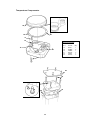
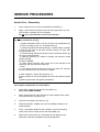
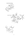
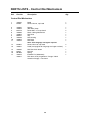
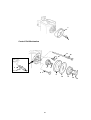
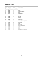
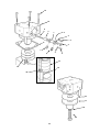
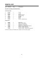
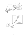
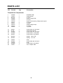
1
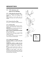
Sigma Delta Vaporizer
Service Manual
Quality and Assurance in Anaesthesia
IMPORTANT
Servicing and Repairs
In order to ensure the full operational life of
the Sigma Delta vaporizer, we recommend
that a periodic service check should be
performed by a Penlon trained engineer.
This check comprises a vaporizer LEAK
TEST and CALIBRATION CHECK.
Note:
(a) The calibration check must be performed
using a suitable agent analyser, e.g. a Riken
refractometer or infrared analyser.
(b) The service check is part of the
recommended pre-use check for your
Anaesthesia System.
Should the calibration checks show the unit
to be outside the specified performance
requirement, then an overhaul service must
be performed.
This
(a)
(b)
(c)
may be done on site by:
A trained user.
An authorised Penlon agent.
A Penlon service engineer.
A calibration and service record section is
provided in the user instruction manual to
maintain a record of the vaporizer's
performance.
For any enquiry regarding the service or
repair of this vaporizer, contact the nearest
accredited Penlon agent* or contact the
Service Department at Penlon Limited.
Service and Repair Department
Penlon Ltd
Abingdon
OX14 3PH
UK
Tel:
+44 (0) 1235 547063
Fax:
+44 (0) 1235 547062
E-mail: [email protected]
Always give as much of the following
information as possible:
1.
Type of equipment
2.
Product name
3.
Serial number
4.
Approximate date of purchase
5.
Apparent fault
(i)
FOREWORD
This manual has been produced to provide
authorised personnel with information on the
function, routine performance, maintenance
checks and repairs, applicable to the Penlon
Sigma Delta vaporizer.
Information contained in the manual is correct at the date of publication. The policy of
Penlon Limited is one of continued improvement to its products. Because of this policy
Penlon Limited reserves the right to make
any changes, which may affect instructions
in this manual, without giving prior notice.
Personnel must make themselves familiar
with the contents of this manual before using
the vaporizer.
Terminology
This manual complies with ISO 4135,
Anaesthetic Apparatus Terminology.
The following additional definitions should be
noted:
Vol.% - shortened form of volumetric percentage.
The commonly used method of expressing
vapour concentrations so that they can be
compared with concentrations of true gases.
100 Vol.% is equivalent to 100% partial pressure in a mixture.
Copyright © Penlon Ltd, 2002
(ii)
CONTENTS
User Responsibility
1
1.
Warnings and Cautions
2
2.
Purpose
4
3.
Description
7
4.
Specification
11
5
Service Procedures
12
5.1
Service Policy
12
5.2
Workplace and Equipment
14
5.3
Pre-Service Checks
18
5.3.1
Leak Test, Bypass Resistance Check (before servicing)
18
5.3.2
Fault Finding (before servicing)
19
5.4
Service Overhaul
21
5.4.1
General Information
21
5.4.2
Health and Safety
21
5.4.3
Service Overhaul Procedure
22
5.4.4
Leak Test, Bypass Resistance, and Calibration Check (after servicing)
64
6
Parts List
68
(iii)
(iv)
USER RESPONSIBILITY
This vaporizer has been built to conform with
the specification and operating procedures
stated in this manual and/or accompanying
labels and notices when checked. assembled, operated, maintained and serviced in
accordance with these instructions provided.
To ensure the safety of this vaporizer it must
be checked and serviced to at least the minimum standards laid out in this manual.
A defective or suspected defective, product
must not, under any circumstances be used.
Statements in this manual preceded by the
following words are of special significance.
WARNING - means there is a possibility
of personal injury to yourself or others.
CAUTION - means there is a possibility of
damage to the instrument or other property.
NOTE - indicates points of particular interest
for more efficient and convenient operation.
The reader must take particular notice of the
warnings, cautions,. and notes printed
throughout the manual.
The user must accept responsibility for any
malfunction which results from non-compliance with the servicing requirements
detailed in section 8.1.
Worn, broken, distorted, contaminated or
missing components must be replaced
immediately. Should such a repair become
necessary it is recommended that a request
for service advice is made to the nearest
Penlon service centre,
This vaporizer and any of its constituent
parts must be repaired only in accordance
with written instructions issued by Penlon
Limited, and must not be altered or modified
in any way without the written approval of
Penlon Limited.
The user of this equipment shall have the
responsibility for any malfunction which
results from improper use, maintenance,
repair, damage or alteration by anyone other
than Penlon Limited or its appointed agents.
This vaporizer must only be supplied to, and
used by, suitably qualified medical practitioners.
Caution: USA and Canadian Federal Law
restricts the sale and use of this device by or
on the order of a physician.
1
1. WARNINGS AND CAUTIONS
WARNINGS
1.
The Sigma Delta vaporizer is to be
sold to, and used on the order of, a
medically qualified practitioner
only.
2.
Anaesthetic agents are poisonous,
and inhaling their vapours, even in
low
(sub-anaesthetic)
concentrations may present a
health hazard.
Care must be taken to avoid
spillage of anaesthetic drugs when
filling or draining the vaporizer.
3.
The procedures described herein
which involve dismantling the
vaporizer must only be performed
after the instrument has been
drained and dried out.
4.
5.
6.
7.
8.
The pharmacopoeia name of the
drug is used on the label according
to BP, USP or Ph EUR.
The user is responsible for
confirming that any trade name of a
drug is equivalent to the registered
name.
9.
Violent movement or tipping of a
filled vaporizer may cause liquid
agent to leak into the control
mechanism and subsequently
deliver uncontrolled doses of
vapour.
The vaporizer must be empty, and
the control must be in the zero
position during transport.
The vaporizer must be purged at
maximum output with 5 L/min flow
of oxygen for 2 minutes, and the
output checked with an analyser
prior to use.
Calibration procedures must only
be performed with the vaporizer
outlet connected to an anaesthetic
gas scavenging system designed
in accordance with national
standards or regulations.
No oil or grease should be
permitted in the vaporizer service
area.
This applies equally to silicone
based lubricants, flammable oil,
and grease.
The Sigma Delta vaporizer is
designed for use only with one
anaesthetic agent - that which is
named on the filler block.
Misdosage will occur if the
vaporizer is filled with the wrong
drug.
Keyed filler devices are provided
on certain models to meet national
and international standards.
10.
The vaporizer control must be in
the zero position during the filling
or draining process. Delivered
concentrations are inaccurate
while the standard filler port is
open or the key filler shoe loose.
The vaporizer must be upright
during filling, to prevent overfilling.
11.
Vaporizers may malfunction if
exposed to excessively high
temperatures, e.g. by storage
above a radiator.
This may
permanently damage the vaporizer.
Maximum storage temperature:
50oC (122oF)
Minimum storage temperature:
-20oC (-5oF).
12.
The Sigma Delta vaporizer must not
be modified or disassembled by
any unauthorised person. It should
be regularly serviced by a Penlon
authorised service agent, trained
technician or engineer and by no
other person (see section 6).
2
Vaporizer outputs are sensitive to
barometric
pressure
and
a
correction factor may be necessary
when assessing the output using
an analyser, for example at high
altitude.
Barometric pressure
effect are not usually of clinical
importance. (See user manual).
WARNINGS AND CAUTIONS
13.
Anaesthetic drugs must be treated
as a pharmaceutical product.
Liquid should never be drained
from a vaporizer into an open
container and then reused.
Contamination is likely.
Always dispose of such drained
liquid as a hazardous chemical.
CAUTIONS
1.
The instructions given in this manual
assume that the service engineer has
received adequate training in the
practice of servicing anaesthetic
apparatus and is familiar with the use
of flowmeters, pressure gauges and
other laboratory equipment.
Details of such procedures are
therefore not included.
2.
Each Sigma Delta vaporizer is a
tested and calibrated unit. It is most
important that components are not
transferred from one unit to another.
In particular, the service engineer
must accept responsibility for
ensuring that agent specific items
such as labelling, keyed fillers, and
control needles are treated as critical
devices and that full records of
vaporizer servicing are kept.
Following any service procedure, a
label to indicate to clinical staff that
the vaporizer has been serviced must
be attached to each unit.
3
2. PURPOSE
The Sigma Delta vaporizer is designed for
incorporation in the fresh gas supply system
of continuous flow anaesthetic machines,
directly connected between the flowmeter
unit and the common gas outlet of the
machine.
The vaporizer is unsuitable for use within a
breathing system 'in circuit' because of the
relatively high internal resistance.
Its purpose is the provision of accurate
concentrations of anaesthetic drugs in the
fresh gas supply, in accordance with the
setting of the control dial, when the fresh gas
supply flow is between 0.2 and 15 litres/min.
Factors affecting output accuracy are listed
in the user instruction manual (Section 7,
Performance Characteristics), which shows
the extent of modifications to the control calibration.
4
Delta Vaporizer
Connector Block Types
Cagemount
Selectatec
Drager
North
American
Drager
5
Figure 1
Gas Flow Path
6
3. DESCRIPTION
3.1
Gas which enters the chamber has to pass
through the narrow passages between the
wicks, becoming saturated with vapour
before emerging through the vapour control
orifice.
The proportion of the total flow which passes
through the vapour chamber is determined
by the relative resistances of the bypass
orifice (which does not vary with control knob
setting, but does vary with temperature) and
the vapour control orifice (which varies only
with control knob setting).
Compensation for total flow variation is
achieved by the design of the orifice
elements which are precision parts.
General Description
The Delta User Manual provides additional
information on the operation of the vaporizer. The
service engineer should have a copy for
reference, in addition to this service manual.
Introduction
The Sigma Delta vaporizer enables the
anaesthetist to add a predetermined amount
of vapour of a volatile drug to the fresh gas
stream supplied to the patient’s breathing
system.
All anaesthetic agents of a volatile nature
have relatively high vapour pressures at
normal room temperature so that this
saturated vapour must be diluted
considerably to produce the concentrations
required clinically.
Temperature Compensation
Compensation for temperature variation
(and therefore changes in vapour pressure,
viscosity etc.) is achieved by the movement
of a bypass control plate (in the form of a
bimetallic strip) against the bypass orifice,
thus changing the area of the orifice. This
device is
mounted within the vapour
chamber so that it is exposed to both gas
and liquid temperatures within the vaporizer.
Gas Flow Path
Figures 1 and 2 show that the vaporizer
contains two paths for gas flow. One is
always open, through the bypass system.
The second, which is open only when the
control knob is moved from zero, is routed
via the closing mechanism vapour chamber,
and, vapour control orifice, and joins up with
the bypass flow in a mixing chamber, and
then on to the vaporizer outlet.
Back-pressure Compensation
Compensation for fluctuating back-pressure
on the vaporizer, as produced by the use of
IPPV in the breathing system, is provided by:
A) the inclusion of a long gas flow path
prior to the closing mechanism system, and
B) a spiral passage after the closing
mechanism,
which prevents reverse flow of vapour from
the chamber into the bypass gas flow.
Vapour Chamber
The vapour chamber contains the liquid
anaesthetic drug, and is filled through the
filler unit to a level shown on the level
indicator. The chamber contains a spiral
wick assembly.
Closing
mechanism
(On/off control)
Gas
Flow
In
Vapour
concentration
control needle
Gas
Flow
Out
Spiral
passage
Saturated
vapour
Vapour
chamber
Bypass
Flow
Mixing
chamber
Figure 2
Gas Flow
Block Diagram
Temperature
compensator chamber
7
DESCRIPTION
3.2
Concentration Control
and Cut-off Mechanism
3.2.1 Control Knob Assembly
The laser engraved dial is etched to match the
performance characteristics of the components
of the individual vaporizer using its allotted
agent.
A self-adhesive label, colour coded for the
agent to be used with the vaporizer, is fixed to
the knob.
3.2.2 Dial Stop Plate Assembly
and Vapour Control Valve
When the control knob is pushed in, the dial
drive plate disengages from the zero position
dial stop (which prevents knob rotation in the
zero (off) position), and opens the closing
mechanism by pushing on the shaft assembly
(see 3.2.4).
The stop plate is now disengaged from the dial
stop and it is free to turn anti-clockwise. A drive
screw produces movement of the vapour
control needle valve within the needle housing,
altering the size of the orifice available for the
passage of vapour.
3.2.3 Dial Stops
The dial stop (zero position) prevents rotation
of the knob assembly in the zero position.
3.2.4 Cut-off Mechanism
When the control knob assembly is in the zero
position, the spring-loaded cut-off valve is
closed. This prevents gas flowing into the
vapour chamber.
When the control knob assembly is pushed in,
the closing mechanism shaft pushes a spring
loaded seal off its seat on a spool assembly.
Gas is then able to flow into the vapour
chamber.
3.2.5 Interlock Mechanism
With two or three interlocked vaporizers on the
anaesthetic machine back bar, initial operation
of the concentration control dial, by pushing on,
activates the interlock system. The interlock
push rods move outwards, ensuring that only
that vaporizer can be in use at any time.
The interlock deactivates as soon as the control
dial is returned to the zero position.
8
Selectatec
Interlock
DESCRIPTION
3.3
Temperature
Compensator (TC)
This device alters the resistance to the flow of
gas passing through a bypass valve.
The temperature sensitive element comprises a
bimetallic assembly that expands/contracts with
increase/decrease in temperature, causing the
bypass plate to move away from, or towards the
TC base.
At low temperature the bypass resistance is
increased, forcing more gas through the vapour
chamber to compensate for the lower vapour
pressure of the liquid. At high temperatures the
reverse is effected.
3.4
Wick Assembly
The large wick assembly consists of a long strip
of wick material attached to a metal backing
strip, and rolled into a spiral. This forms a single unit cartridge assembly for ease of replacement.
9
DESCRIPTION
3.5
Filler Systems and
Agent Level Indicator
3.5.1 Agent Specific (Keyed) Filler
This unit is designed to be used with a bottle
adaptor only - refer to the vaporizer user
manual.
Bottle adaptors for each agent type are
available - see section 10, in the user instruction
manual.
3.5.2 Screw Cap Pour Filler
This unit has a screw-plug, sealed filler opening.
3.5.3 Quik-Fil Filler
This unit is designed to be used with an agentspecific nozzle, permanently attached to the
agent bottle.
When the nozzle is inserted into the filler block,
a valve opens inside the filler block.
When the nozzle is pressed further into the filler
block, a valve in the nozzle opens and agent
flows into the vaporizer.
The filler block utilises an air lock which
automatically stops the filling process at the
maximum fill position.
The vaporizer is drained through a separate
valve in the base of the filler block.
3.5.4 Agent Level Indicator
The level indicator is a glass tube with
maximum and minimum fill level marks printed
on the glass.
Provided the vaporizer is upright, with the
control knob set at zero, the chamber cannot be
overfilled as the design of the air escape ports
facilitates air trapping at the maximum safe
level.
On agent specific (keyed) filler models, an
overfill hole drains excess agent from the filler
system.
On screw cap filler models, a drain hole is
included in the side of the filler block to drain the
filler funnel level should excess agent be tipped
into the filler block during filling.
10
4. SPECIFICATION
4.1
Physical Dimensions
Cagemount
Selectatec Compatible with Interlock
Drager 'plug in' Compatible
Width
Height
Depth
133
120
100
219
242
242
158
190
190
Dimensions given above are in millimetres
NOTE
The figures for Depth relate to Key Filler (Agent Specific) and Quik Fil models.
To calculate the depth dimension for Screw Cap Filler models, subtract 11 mm from the figures given above.
4.2
Weight
Approximate weight: 4.8 kg.
4.3
Capacity
Volume at MAX mark
250 ml (nominal)
Volume at MIN mark
35 ml (nominal)
NOTE After draining, approximately 60 ± 10 ml of liquid is retained by the wick.
4.4
Filling System
Key Filler (Agent Specific)- Use with corresponding agent specific filler adaptor, see section 10 (USER
Manual), Ordering Information.
Pour Fill (Screw Cap)
Quik Fil - Sevoflurane only Use with corresponding agent specific bottle.
4.5
Control Dial Scale
The control dial is marked as follows:
From 0 to 2% vol, by intervals of 0.2% vol
From 2% to maximum, by intervals of 0.5% vol
The control dial is marked '0' at zero
4.6
Patents
The Sigma Delta is protected by UK and foreign patents.
4.7
Temperature Range
Operating Temperature Range
Storage Temperature Range
Storage in Transit (up to 7 days)
4.8
15 to 35oC (58 to 95oF)
-20 to 50oC (-5 to 122oF)
-40 to 60oC (-40 to 149oF)
Flow Range
Operating Flow Range:
0.2 to 15 litres/min.
See section 7.4.1 (User Manual) for output accuracies at extreme conditions.
4.9
Pressure Range
Operating Pressure Range
0 to 5 kPa (0 to 0.7 psi)
Maximum Manifold Pressure
38 kPa (5.5 psi)
Maximum Test Pressure
38 kPa (5.5 psi)
11
5. SERVICE PROCEDURES
5.1
Service Policy
The Sigma Delta must only be serviced at an authorised
service centre or by Penlon-trained technicians in
accordance with the following procedure.
(a)
The calibration should be checked periodically under
controlled conditions and a leak test performed.
Detailed information on the use of the Riken
Analyser is given in the following pages.
Record the measured values in section 11 in the
vaporizer user manual.
(b)
Successive sets of figures should be compared to
determine if performance is deteriorating.
Should deterioration be detected, a service should
be carried out to restore normal operation.
(c)
A major overhaul must be performed every ten years
(Halothane models - 5 years) to maintain
performance within the specification.
(d)
The Selectatec compatible vaporizer locking system
should be inspected during the vaporizer calibration
test, and if damage to the locking shaft is suspected,
the device must be referred to a Penlon certified
engineer.
(e)
Interlock system vaporizers function test the interlock system during the
vaporizer calibration test.
(d)
Quik-Fil system - at regular intervals (3 monthly
minimum, 6 monthly maximum), filling and draining
must be checked under controlled conditions
NOTE
The user must accept responsibility for any malfunction which
results from non-compliance with the above requirements.
Returning the Vaporizer for Service / Repair
The vaporizer must be drained and allowed to dry out
before packing.
Always use the original packaging, to prevent damage
during transit.
12
SERVICE PROCEDURES
The correction factor is ± 1.5% of readings, which
is negligible in view of the accuracy of the
instrument.
Temperature correction is therefore not required,
but the temperature should be measured and
recorded to ensure that the test is carried out
within the specified range.
Checking Vaporizer Output
Calibration Procedure using the
Riken Analyser
The Riken Model 1F-18 is normally calibrated by
the manufacturer for measuring up to 8% vol.
Halothane or up to 9% vol. Sevoflurane, either in
air or in oxygen.
Service checks on the vaporizer must be
performed with oxygen if the vaporizer is checked
on an anaesthetic machine.
Use air or oxygen if the vaporizer is checked in a
test laboratory.
Changes of barometric pressure due to weather
are not normally of significance and can be
ignored.
Altitude can, however, have significant effects
and the following correction factors should be
applied when appropriate.
The Riken reading multiplied by the stated
correction factor gives the true concentration
corrected to Standard Temperature and Pressure
(STP).
CAUTION
A) It is essential that the gas used during service
checks is recorded,
B) The reference cell of the Riken must be
purged with the appropriate gas before
measurements are made.
Agents
The Riken gas analyser measures the refractive
index of the gases and vapours and, although
normally calibrated for measuring halothane, the
instrument can also measure other vapours if an
appropriate correction factor is applied.
To obtain the true concentration of gases other
than halothane multiply the reading shown on the
Riken by the correction factors given below.
Altitude
Factor
600 m
(2000 ft)
1200 m
(4000 ft)
1800 m
(6000 ft)
0.9
Barometric
pressure
(for reference)
910 mb
0.85
850 mb
0.8
813 mb
Method of reading the Riken
Analyser
1.
Carrier Gas
The refractive index of oxygen is higher than that
of air so that,
(a) the unit must be re-zeroed if the carrier gas is
changed, and
(b) the scale must be adjusted by a correction
factor, applied by multiplying the Riken scale
reading to obtain the true concentration.
2.
Correction Factors
Halothane in Air Riken:
Halothane
Enflurane
Isoflurane
Factor (using air)
1
1.05
1.06
Sevoflurane
1.05
3.
Factor (using O2)
1.06
1.11
1.12
4.
1.10
Halothane in Oxygen Riken:
Halothane
Enflurane
Isoflurane
Sevoflurane
Factor (using air)
0.95
0.99
1
0.99
Factor (using O2)
1
1.05
1.06
1.05
5.
Temperature and Barometric Pressure
Calibration checks must be performed at a
temperature between 19 and 21oC.
13
Readings may be taken from a tee-piece
connected to the common gas outlet of the
anaesthetic machine.
An AGS system must be connected.
The sampling tube must be nylon or PTFE
(which do not absorb vapours).
Rubber sleeves may be used to make end
connections but there must be minimal
length of rubber exposed to the gases
being sampled.
Sample by 2 or 3 squeezes of the hand
bulb. Wait for fringe movement to cease
before taking the reading.
After each resetting of the vapour control,
time must be allowed for the output to
stabilise.
Suggested timescale:
2 L/min flow - wait 4 minutes
4 L/min flow - wait 2 minutes
8 L/min flow - wait 1 minute
a) The vaporizer must be half full, and
rigidly supported in its correct operating
position.
b) Temperatures must be stabilised for
approximately 4 hours before checking
c) The temperature must be in the range
19 to 21oC.
SERVICE PROCEDURES
Sample of Service Record Page
(see section 11 in the Delta User Manual)
Test Period
1
Vaporizer serial number:
Date:
Signature:
Print name:
Carrier Gas
Leak Test (at 200 mmHg for minimum 60 secs)
Pressure must not drop below 180 mm Hg
Set
Tolerance
0.0
0 - 0.1
0.2
0.14 - 0.26
0.6
0.45 - 0.75
1.0
0.8 - 1.2
3.0
2.4 - 3.6
*4.0
3.2 - 4.8
5.0
4.0 - 6.0
**7.0
**8.0
**7.0
5.6 - 8.4
5.0
4.0 - 6.0
3.0
2.4 - 3.6
1.0
0.8 - 1.2
0.6
0.45 - 0.75
0.2
0.14 - 0.26
6.4 - 9.6
5.6 - 8.4
0.0
0 - 0.1
* 4% Halothane vaporizer only
** 7% and 8% vaporizers only
Bypass resistance at 4 L/min
14
2
3
4
SERVICE PROCEDURES
5.2
5.2.2 Test connectors and
equipment
(available from Penlon)
Workplace and Equipment
NOTE
For complete safety when servicing this device,
full reference must be made to the WARNINGS
and CAUTIONS listed in section 1.
Pressure gauge tee connector
53196
Flexible hose with cagemount female
connector end
37019
Blanking plug with pressure gauge connector
(Cagemount male)
37018
Nylon Catheter
52605
WARNING
Adequate ventilation of the work area must be
provided. During calibration procedures,
connect the outlet of the vaporizer to an
anaesthetic gas scavenging system that
conforms to your national standards or
regulations.
Exhaust tubing
(22 mm diameter breathing hose)
Environment - servicing must be carried out
in a stable temperature environment,
preferably with thermostatic control or air
conditioning, to maintain the temperature
within 22°C ±1°C.
Gas Supply - flow check for bypass
resistance measurement must be carried out
using air. Calibration after servicing must be
carried out using oxygen.
Small tools - as listed throughout the
service procedures listed in this manual, and
in the following pages.
Gauges, etc. - as listed in the following
pages.
Test Rigs - layouts and components are
listed in the following pages.
5.2.1
57004
5.2.3 Special Purpose Service Tools
and Equipment
(available from Penlon)
Test Connection Block
410579
Sample Tee Connector
53196
Blanking Plug with Pressure Gauge
Connector
37018
Needle Housing Locknut Tool
410644
Small Wick Assembly Tool
410659
Needle Bal Seal Tool
410660
Interlock Checking Tool
410582
TC Assembly Tool (includes Bi-metallic
Standard Equipment
Pressure regulator 0 - 400 kPa (0 - 60 psig)
Pressure gauge
0 - 400 kPa (0 - 60 psig)
Pressure gauge
0 - 40 kPa (0 - 3000 mmHg)
Pressure gauge or
water column
0 - 10 kPa (0 - 100 cm H2O)
Flow meter unit
0 - 10 L/min
Pressure isolating valve
Leak detection fluid
Torque driver
0 - 10 Nm
Strip Assembly Tool)
410647
TC Hinge Assembly Tool
410694
Dial Stop Setting Tool
410695
Closing Mechanism Removal Tool
410650
Interlock Bush Tool
408889
Needle Setting Tool
410602
NAD Interlock Tool
410772
5.2.4
Test Apparatus
Leak Test
- 5.2.4.1 (Test Apparatus A)
Gas analyser - The preferred form of
analysis apparatus is an interferometer.
However, if used carefully, the following
instruments are also suitable for a calibration
check:
Infrared analyser
Mass spectrometer
Molecular absorption meter
The selected analyser should have a
sensitivity better than ± 0.1%.
Flow Check for Bypass Resistance Measurement
- 5.2.4.2 (Test Apparatus B )
Calibration Check
- 5.2.4.3 (Test Apparatus B adapted for
calibration)
A schematic layout for each apparatus is
given in the following pages.
15
SERVICE PROCEDURES
G
Pressure
Gauge
E
D
C
Pressure
Gauge
Vaporizer
Flowmeter
Unit
F
Blanking
Plug
B
Regulator
A
Air or
Oxygen
Supply
5.2.4.1 Test apparatus A
For leak testing
A
B
C
D
E
F
G
-
Air or Oxygen supply
Pressure regulator
0 - 400 kPa (0 - 60 psig)
Pressure gauge
0 - 400 kPa (0 - 60 psig)
Flowmeter unit
0 - 10 L/min
Vaporizer on Test connection block (410579)
Blanking plug with pressure gauge connector (cagemount male) (37018)
Pressure Gauge
0 - 40 kPa (0 - 300 mmHg)
16
SERVICE PROCEDURES
E
Pressure gauge
or Water Column
D
C
Pressure
Gauge
Vaporizer
In
Flowmeter
Module
(mounted on
test connection
block 410579)
Out
Sample connector
tee (53196)
Vaporizer must be in
the OFF position
B
Regulator
5.2.4.2 Test Apparatus B
Flow check for measurement and adjustment of
bypass resistance
A - Air supply
B - Pressure regulator
C - Pressure gauge
D - Flow meter unit
E - Pressure gauge or water column
A
Air
Supply
0
0
0
0
-
400 kPa (0 - 60 psig)
400 kPa (0 - 60 psig)
10 L/min
100 cm H2O
- Sample connector tee (53196)
- Vaporizer mounted on Test connection block (410579)
NOTE While the bypass resistance is being measured, nothing must be
attached to the outlet of the vaporizer.
E
D
C
Pressure
Gauge
Flowmeter
Module
Analyser
F
Vaporizer
G
Sample connector
tee (53196)
B
Regulator
A
Oxygen
Supply
5.2.4.3 Test Apparatus B
Adapted for calibration test
A
B
C
D
E
G
-
Oxygen supply
Pressure regulator
0 - 400 kPa (0 - 60 psig)
Pressure gauge
0 - 400 kPa (0 - 60 psig)
Flowmeter unit
0 - 10 L/min
Vaporizer mounted on Test connection block (410579)
Exhaust tubing (22 mm diameter breathing hose)
- Sample connector tee (53196)
17
Flow to
scavenge
system
SERVICE PROCEDURES
5.3
Pre-Service Checks
5.3.1
Leak Test and Bypass Resistance Measurement
(Before servicing)
NOTE:
Anaesthetic gas scavenging equipment must be connected during these
tests.
1.
Drain the vaporizer and discard the contents - see section
5 in the vaporizer user Manual.
Do NOT reuse the anaesthetic agent.
Close the filler system.
2.
Check for leaks from the vaporizer:
Use Test Apparatus A (5.2.4.1),and set a pressure of 200
mmHg.
Measure, and record the pressure drop after a minimum of
60 seconds.
3.
Measure the Bypass Resistance:
Allow 4 hours for temperature stabilisation.
Use Test Apparatus B (5.2.4.2) to measure, and record the
vaporizer Bypass Resistance, using a flow of Air at 4 L/min.
18
SERVICE PROCEDURES
5.3.2
Fault Finding (Before servicing)
Fault
1.
Low or zero
output at all
settings
Possible Cause
Treatment
Reference
(a) Insufficient liquid in chamber
(a) Refill / check level
indicator
User Manual
(b) Leak to atmosphere from
(b) Service
5.4
(c) Cut-off mechanism not
operating
(c) Check operation
of closing mechanism
shaft
5.4
(d) Incorrect needle setting
(d) Service
5.4
(e) Bypass resistance out of
adjustment
(e) Adjust
5.4
(f) Wrong agent
(f) Drain and dry
User Manual
WARNING
If Halothane has been used in a non-Halothane vaporizer, DO NOT USE that vaporizer
until all traces of Halothane have been removed.
To prevent the possibility of malignant hypothermia, the vaporizer must be completely
disassembled.
2.
Low output at
high setting
only
(g) Leaking sight glass seals
(g) Fit new seal
5.4 (complete service
not necessary)
(h) Damaged sealing counterbores
on Selectatec block
(h) Fit new block
5.4
(j) Worn or damaged claws on
Selectatec block locking shaft
(j) Fit new locking
shaft
5.4 (complete service
not necessary)
(a) Contaminated wick
(a) Renew wick as part
of Service
5.4
(b) Leaking wick sealing
washer
(b) Renew wick as part
of Service
5.4
3.
Excessive
(a) Worn, or broken vapour control
variation in
needle valve spring
output,
when the set
(b) Jamming needle
value required
is selected
(c) Loose needle drive
(i) clockwise,
and then
(ii) anti-clockwise.
(a) Return unit to Penlon
or authorised distributor/agent
19
(b) Service
5.4
(c) Service
5.4
SERVICE PROCEDURES
Fault
Possible Cause
Treatment
Reference
(a) Cut-off mechanism
O-seals leaking
(a) Service
5.4
(b) Leak between seal
assembly and spool
(b) Service
5.4
(c) Leaks through TC
assembly
(c) Service
5.4
(d) Worn needle or seat
(d) Service
5.4
(e) Jamming needle
(b) Service
5.4
(f) Incorrectly adjusted needle
and seat
(b) Service
5.4
(a) Bypass out of adjustment
(b) Service
5.4
(b) Bypass control plate
contamination
(b) Return unit to
Penlon, or authorised
distributor/agent
(c) Bypass exit port partially
blocked
(b) Service
5.4
(a) Leak between TC cover and
chamber
(b) Service
5.4
7.
Air leaking
from base
during test
(a) Leak between TC base and
body
(b) Service
5.4
8.
Air or vapour
leak around
valve block
(a) Leak between valve block
and body
(b) Service
5.4
4.
Zero not obtained
5.
High output
6.
Agent leaking
from base
20
SERVICE PROCEDURES
5.4 Service Overhaul
5.4.1 General Information
If the vaporizer fails the calibration test a Service
Overhaul must be carried out.
NOTE
A service overhaul must be carried out at a maximum 10
year interval even if performance appears satisfactory.
This is a mandatory preventive maintenance
requirement.
Preparation
The vaporizer must be removed from the
anaesthetic machine for this service.
The vaporizer must be drained of anaesthetic
agent and then dried - pass an air flow of 10 L/min
through it with the control at maximum setting until
all trace of vapour at the output port is eliminated.
Check using an agent analyser.
Bypass Resistance Measurement
Measure and record the bypass resistance before
and after servicing - see 5.3.1.
Service Area
These procedures should be carried out in a
laboratory room at a temperature
of 22°C ± 1°C, not varying by ± 1°C over the test
period.
Approximately 1 metre of bench space is required.
A scavenge system for anaesthetic vaporizers
should be in operation.
A supply compressed air, dry and clean, at 0.6 bar
(8.7 psi) should be available.
O seal Lubrication
Lightly lubricate O-seals / O-rings with PTFE
based, oxygen compatible, lubricant.
APPLY SPARINGLY.
5.4.2
Health and Safety
Cleaning - always comply with the local health and
safety regulations when using solvents to clean
components.
Loctite Superlube - use sparingly.
Prolonged skin contact may cause irritation.
Always follow the manufacturer's instructions
when using this product.
21
SERVICE PROCEDURES
5.4.3 Service Overhaul
Procedure
CAUTION
Before servicing, always drain the vaporizer follow the instructions given in the User Manual.
Do not invert the vaporizer until the wicks are
removed.
Leak Test and Bypass Resistance
(See section 5.3.1)
Before dismantling the vaporizer:
a) Leak test the vaporizer.
b) Measure the bypass resistance.
Dismantling the vaporizer
Connector Block
1.
Remove the four M4 cap-head screws
(1) and the connector block (2).
2.
Remove the O-seals (3) (connector
block to valve block).
3.
Remove the top label (4) and lid (5)
(M6 countersunk screw).
Dial Assembly
4.
Remove the dial label (6), and
discard.
5.
Remove the two M3 cap head screws
and dial assembly (7).
6.
Remove the circlip (8) from the shaft,
and remove the dial drive (9).
7.
Remove the dial bezel (10) - two M3
cap-head screws.
22
Connector Blocks
4
4
5
3
5
2
2
3
1
1
Selectatec
Cagemount
4
4
5
2
3
3
5
2
1
1
North American Drager
Drager
Dial Assembly
7
6
9
8
10
23
SERVICE PROCEDURES
Interlock - Selectatec
8.
Remove the interlock shaft (11) and spring
(12).
Note - on Cagemount, Drager and North
American Drager models a dial return shaft
(plus spring) is fitted.
Interlock - Drager and North American
Drager
9.
Remove the interlock system components
(13).
Dial Stops and Closing Mechanism
Shaft - All models
10.
Remove the dial ‘zero’ lock screw (14)
11.
Remove the closing mechanism shaft (15).
12.
Remove the dial ‘max’ stop (16).
24
Selectatec Interlock Shaft,
Dial Stops and Closing
Mechanism Shaft
12
14
15
16
Drager Interlock
North American
Drager Interlock
13
25
11
SERVICE PROCEDURES
13.
Needle drive assembly:
Remove the two M3 pan-head screws and
washers (1).
Unscrew the needle drive assembly (2)
Note: left-hand thread.
14.
Needle drive housing - Inspection
Inspect the threads inside the housing (3).
If the threads are worn or damaged, the
housing and needle drive assembly must be
replaced with new components.
Removing the housing:
a) Remove the M3 grub screw (4). The housing
must be pushed out from the rear of the block.
Note that the needle assembly must be removed
to gain access to the housing (see operation 21,
page 30).
b) Discard the housing.
c) Unscrew the setting screw from the needle
drive assembly, and retain for fitment to the new
drive.
d) Discard the needle drive.
Refitting the housing - see page 54
If the housing threads are in good condition,
continue with the standard overhaul procedure.
15.
Dismantling
assembly:
the
needle
drive
Slacken the two M3 grub screws (5).
Insert a screwdriver blade into the assembly,
and unscrew the setting screw (6).
26
3
Needle Drive
Assembly
2
1
1
4
Needle
Drive
Housing
- renew if
the threads
are worn or
damaged
3
6
5
5
Dismantling the
Needle Drive
Assembly
27
SERVICE PROCEDURES
Interlock - Selectatec
8.
Remove the interlock shaft (11) and
spring (12).
Note - on Cagemount, Drager and
North American Drager models a dial
return shaft (plus spring) is fitted.
Interlock - Drager and North
American Drager
9.
Remove the interlock
components (13).
system
Dial Stops and Closing
Mechanism Shaft - All models
10.
Remove the dial ‘zero’ lock screw (14)
11.
Remove the closing mechanism shaft
(15).
12.
Remove the dial ‘max’ stop (16).
28
Valve Block
1
2
8
10
11
9
3
7
4
13
Closing Mechanism
12
Wicks
4
5
6
29
SERVICE PROCEDURES
13.
Needle drive assembly:
Remove the two M3 pan-head screws
and washers (1).
Unscrew the needle drive assembly (2)
Note: left-hand thread.
14.
Needle
drive
Inspection
housing
-
Inspect the threads inside the housing
(3).
If the threads are worn or damaged,
the housing and needle drive
assembly must be replaced with new
components.
Removing the housing:
a) Remove the M3 grub screw (4). The
housing must be pushed out from the
rear of the block.
Note that the needle assembly must be
removed to gain access to the housing
(see operation 21, page 30).
b) Discard the housing.
c) Unscrew the setting screw from the
needle drive assembly, and retain for
fitment to the new drive.
d) Discard the needle drive.
Refitting the housing - see page 54
If the housing threads are in good condition, continue with the standard overhaul procedure.
15.
Dismantling the needle drive
assembly:
Slacken the two M3 grub screws (5).
Insert a screwdriver blade into the
assembly, and unscrew the setting
screw (6).
16.
Valve Block and Wicks:
Remove the four M6 cap-head screws
(1) and lift the valve block (2) from the
body.
30
4
Needle Assembly
8
5
3
7
12
6
2
11
1
10
9
31
SERVICE PROCEDURES
24.
Base Assembly and Cover
Remove the anti-tamper label (1).
Remove the four M3 screws and bottom cover
(2).
Remove the four countersunk screws, and
remove the base assembly (3), and seal (4).
25.
Temperature Compensator (TC)
Components:
Remove the six screws (5), the cover (6), the
seal (7), and the spring (8).
Discard the seal.
26.
Remove the two screws (9), and plate (10).
Remove the two screws (11), and separate
the remaining TC components:
TC plate (12),
Upper and lower small plates (13 / 14)
Hinge (15).
Note
The lower plate (14) and the TC plate (12)
must be used together on the same vaporizer.
27.
Remove the grub screw (16).
28.
Remove the two screws (17), and the bimetallic strip (18), and spacers (19).
Note orientation for correct refitment.
29.
Invert the TC assembly and remove the
bypass resistance adjusters (20).
30.
Remove the O-seals (21) from the adjusters
and discard.
32
Base Assembly
2
3
1
4
Temperature Compensator
9
6
11
16
13
10
7
15
12
14
8
17
18
5
19
21
20
21
20
33
SERVICE PROCEDURES
Filler Blocks
Quik-Fil Filler Block
Removal
CAUTION
Do not remove the filler block until the wicks are removed.
1.
2.
3.
Remove the label (1).
Remove the two screws (2), and detach the filler block (3)
from the vaporizer.
Remove the five O-seals (4), and discard.
Dismantling
4.
Carefully remove the the sight glass retaining screw
assembly (5).
CAUTION
Use a correct size flat-head screwdriver (see illustration),
to prevent damage to the slot in the screw.
Discard the O-seals (6).
5.
Withdraw the sight glass (7), insert (8), and top O-seal (9).
Discard the O-seal.
Discard the ball (10).
6.
Remove the cap (11), screw (12), and withdraw the drain
screw (13)
7.
Remove the filler block cap (14).
8.
Unscrew the grubscrew (15) and remove the sleeve
assembly (16).
Remove and discard the seals (17) and (18).
9.
10.
Filler Cap - dismantling:
Remove the two screws (19), and separate the cap insert
(20) from the cap.
Remove the O-seals (21) and (22), and discard.
Remove the cap insert seal (23) and discard.
Reassembly
O seal Lubrication
Lightly lubricate O-seals / O-rings with PTFE based, oxygen
compatible, lubricant. APPLY SPARINGLY.
11.
12.
13.
Fit a new cap insert seal (23) - note orientation - square
face into insert.
Fit a new cord (24).
Reverse the procedure (operations 4 to 9) given above.
Note:
Ensure free rotation of bush (25) after assembly
Tighten the screws (19) to 0.42 Nm.
Apply Loctite Activator 7471, then Loctite 222 to the
threads of grubscrew (15), screw (12) and screws (2).
34
24
Service Kit Parts
Ref.
Part No.
2
019154
6 (& 9) 041253
7
410594
8
410640
10
011273
11
409043
12
019011
13
409027
15
019011
17
041244
18
409050
21
041231
22
041245
23
409056
24
011135
22
21
25
20
23
14
19
17
18
15
16
3
2
4
15
1
9
8
12
11
13
7
10
6
5
5
4
35
Qty.
2
3
1
1
1
1
1
1
1
1
1
1
0.12 m
SERVICE PROCEDURES
Key Filler Block
Removal
CAUTION
Do not remove the filler block until the wicks are removed.
1.
2.
3.
Remove the label (1).
Remove the two screws (2), and detach the filler block (3)
from the vaporizer.
Remove the five O-seals (4), and discard.
Dismantling
4.
Carefully remove the the sight glass retaining screw
assembly (5).
CAUTION
Use a correct size flat-head screwdriver (see illustration), to
prevent damage to the slot in the screw.
Discard the O-seals (6).
5.
Withdraw the sight glass (7), insert (8), and top O-seal (9).
Discard the O-seal.
Discard the ball (10).
6.
Slacken the key filler control screw (11), and detach the key
(12).
7.
Remove the four screws (13) and detach the side plate (14)
and seal pad (15).
9.
Open the flip top control (16) and remove the two screws (17).
10. Withdraw the filler control assembly (18).
11.
Remove the pin (19) and detach the lever (20).
12. Remove the screw (21), and separate the components, as
illustrated.
Note the orientation of the Bal seal (22)
Discard all seals.
Reassembly
O seal Lubrication
Lightly lubricate O seals / O rings with PTFE based, oxygen
compatible, lubricant.
APPLY SPARINGLY.
13.
Reverse the procedure (operations 2 to 12) given above.
Note:
Apply Loctite Superlube to the threads of screw (11).
Tighten screws (13) to 1.2 Nm
Apply Loctite Activator, then Loctite 242 to the threads of
screw (21), and to the filler shaft at A.
Apply Loctite Activator 7471, then Loctite 222 to the threads
of screws (17) and (2).
36
Key Filler Block
20
16
17
18
19
22
A
17
23
21
3
13
14
11
4
15
2
9
1
8
7
12
10
9
5
5
4
Service Kit Parts
Ref.
2
7
8
9
10
12
13
15
17
21
22
23
Part No.
019154
410594
410640
041253
011273
410607 (Iso/Sevo)
410608 (Hal/Enf)
019009
408294
019122
01059
042812
410685
Qty.
2
1
1
3
1
1
1
4
1
1
1
1
1
37
SERVICE PROCEDURES
Pour-Fill Filler Block
Removal
CAUTION
Do not remove the filler block until the wicks are removed.
1.
2.
3.
Remove the label (1).
Remove the two screws (2), and detach the filler block (3)
from the vaporizer.
Remove the five O-seals (4), and discard.
Dismantling
4.
Carefully remove the the sight glass retaining screw assembly
(5).
CAUTION
Use a correct size flat-head screwdriver (see illustration), to
prevent damage to the slot in the screw.
Discard the O-seals (6).
5.
Withdraw the sight glass (7), insert (8), and top O-seal (9).
Discard the O-seal.
Discard the ball (10).
6.
Remove the cap (11), screw (12), and withdraw the drain
screw (13)
7.
Remove the filler block cap (14).
Filler Cap - dismantling:
Remove the two screws (15), and separate the cap insert (16)
from the cap.
Remove the O-seals (17) and (18), and discard.
8.
Remove the cap insert seal (19) and discard.
Reassembly
O seal Lubrication
Lightly lubricate O seals / O rings with PTFE based, oxygen
compatible, lubricant.
APPLY SPARINGLY.
9.
10.
11.
Fit a new cap insert seal - note orientation - square face into
insert.
Fit a new cord (20).
Reverse the procedure (operations 4 to 8) given above.
Note:
Tighten the cap insert screws (14) to 0.42 Nm.
Apply Loctite Activator 7471, then Loctite 222 to the threads
of screw (12) and screws (2).
Ensure free rotation of bush (21) after assembly
38
Pour-Fill Filler Block
Service Kit Parts
Ref.
Part No.
2
019154
6 (& 9) 041253
7
410594
8
410640
20
Qty.
2
3
1
1
18
10
11
12
13
17
18
19
20
011273
409043
019009
409027
041215
041245
409056
011135
1
1
1
1
1
1
1
0.12 m
17
21
16
19
15
14
4
3
2
1
9
8
12
11
7
10
6
5
5
4
39
13
SERVICE PROCEDURES
Filler Blocks
Quik-Fil Filler Block
Removal
CAUTION
Do not remove the filler block until the wicks are removed.
1.
2.
3.
Remove the label (1).
Remove the two screws (2), and detach the filler block
(3) from the vaporizer.
Remove the five O-seals (4), and discard.
Dismantling
4.
Carefully remove the the sight glass retaining screw
assembly (5).
CAUTION
Use a correct size flat-head screwdriver (see
illustration), to prevent damage to the slot in the screw.
Discard the O-seals (6).
5.
Withdraw the sight glass (7), insert (8), and top O-seal
(9).
Discard the O-seal.
Discard the ball (10).
6.
Remove the cap (11), screw (12), and withdraw the drain
screw (13)
7.
Remove the filler block cap (14).
8.
Unscrew the grubscrew (15) and remove the sleeve
assembly (16).
Remove and discard the seals (17) and (18).
9.
10.
Filler Cap - dismantling:
Remove the two screws (19), and separate the cap
insert (20) from the cap.
Remove the O-seals (21) and (22), and discard.
Remove the cap insert seal (23) and discard.
Reassembly
O seal Lubrication
Lightly lubricate O-seals / O-rings with PTFE based, oxygen
compatible, lubricant. APPLY SPARINGLY.
11.
12.
13.
Fit a new cap insert seal (23) - note orientation - square
face into insert.
Fit a new cord (24).
Reverse the procedure (operations 4 to 9) given above.
Note:
Ensure free rotation of bush (25) after assembly
Tighten the screws (19) to 0.42 Nm.
Apply Loctite Activator 7471, then Loctite 222 to the
threads of grubscrew (15), screw (12) and screws (2).
40
4
5
7
8
9
11
10
3
13
12
3
16
6
5
16
2
41
1
SERVICE PROCEDURES
Key Filler Block
Removal
CAUTION
Do not remove the filler block until the wicks are
removed.
1.
2.
3.
Remove the label (1).
Remove the two screws (2), and detach the filler
block (3) from the vaporizer.
Remove the five O-seals (4), and discard.
Dismantling
4.
Carefully remove the the sight glass retaining
screw assembly (5).
CAUTION
Use a correct size flat-head screwdriver (see
illustration), to prevent damage to the slot in the
screw.
Discard the O-seals (6).
5.
Withdraw the sight glass (7), insert (8), and top
O-seal (9).
Discard the O-seal.
Discard the ball (10).
6.
Slacken the key filler control screw (11), and
detach the key (12).
7.
Remove the four screws (13) and detach the side
plate (14) and seal pad (15).
9.
Open the flip top control (16) and remove the two
screws (17).
10. Withdraw the filler control assembly (18).
11.
Remove the pin (19) and detach the lever (20).
12. Remove the screw (21), and separate the
components, as illustrated.
Note the orientation of the Bal seal (22)
Discard all seals.
Reassembly
O seal Lubrication
Lightly lubricate O seals / O rings with PTFE based,
oxygen compatible, lubricant.
APPLY SPARINGLY.
13.
Reverse the procedure (operations 2 to 12) given
above.
Note:
Apply Loctite Superlube to the threads of screw
(11).
Tighten screws (13) to 1.2 Nm
42
Selectatec
6
1
6
5
3
2
4
5
3
Cagemount
1
1
2
43
4
2
SERVICE PROCEDURES
Filler Blocks
Quik-Fil Filler Block
Removal
CAUTION
Do not remove the filler block until the wicks are
removed.
1.
2.
3.
Remove the label (1).
Remove the two screws (2), and detach the
filler block (3) from the vaporizer.
Remove the five O-seals (4), and discard.
Dismantling
4.
Carefully remove the the sight glass
retaining screw assembly (5).
CAUTION
Use a correct size flat-head screwdriver (see
illustration), to prevent damage to the slot in
the screw.
Discard the O-seals (6).
5.
Withdraw the sight glass (7), insert (8), and
top O-seal (9).
Discard the O-seal.
Discard the ball (10).
6.
Remove the cap (11), screw (12), and
withdraw the drain screw (13)
7.
Remove the filler block cap (14).
8.
Unscrew the grubscrew (15) and remove the
sleeve assembly (16).
Remove and discard the seals (17) and (18).
9.
10.
Filler Cap - dismantling:
Remove the two screws (19), and separate
the cap insert (20) from the cap.
Remove the O-seals (21) and (22), and
discard.
Remove the cap insert seal (23) and discard.
Reassembly
44
5
7
12
6
8
13
9
12
10
Drager
1
2
11
3
4
14
North American Drager
15
14
45
SERVICE PROCEDURES
Reassembling the vaporizer
NOTE
A)
Clean all components before refitting.
B)
Use new seals and O-rings
O seal Lubrication:
Lightly lubricate O-seals / O-rings with
PTFE based, oxygen compatible, lubricant.
APPLY SPARINGLY.
C)
Use new screws where indicated
D)
Use Loctite Activator 7471 on screw threads
before applying Loctite 222 or 242, unless
otherwise indicated in the text.
Valve block
1.
Needle assembly:
Fit new O-rings (1A, 1B and 1C).
Fit the needle (2) into the housing (3).
Fit a new Bal seal (4) to the needle (2) - use
Service Tool Set 410660.
Refit the housing and needle assembly to the
valve block.
Fit a new grubscrew (5).
Use Loctite Activator 7471, then Loctite 242 on
the screw threads.
Fit the spring (6), and use Service Tool 410633
to fit the locknut (7).
2.
Fit the valve block lower cover (8) and a new
seal (9).
Secure with the M12 bolt (10) and new washer
(11).
NOTE:
Use Loctite Activator, then Loctite 242 on the
bolt threads.
(Apply SPARINGLY, to prevent excess Loctite
running into the cover or block.)
Tighten to 30 Nm.
3
Fit the valve block assembly, and a new seal
(12), to the vaporizer body. The seal must be
fitted with the red line uppermost.
Secure with four new M6 cap-head screws
(13).
NOTE:
Apply Loctite Superlube to the four screws.
Tighten to 6 Nm.
46
5
1C
1B
3
1A
4
9
2
6
8
7
11
10
13
12
Service Kit Parts
Ref.
Part No.
Qty.
1A
1B
1C
4
5
9
11
12
13
041214
041239
041243
042820
019028
410591
410638
410550
019069
1
1
1
1
1
1
1
1
4
47
SERVICE PROCEDURES
Wicks:
4.
Assemble the small wick components,
using service tool 410659:
Fit the metal wick tube (1) inside the
tool 2).
Fit the cloth sheath (3) over the tool.
Withdraw the tool.
5.
Fit new wick sealing discs (4).
Note: refit the same number of discs
as removed.
6.
Fit the large wick (5), and small wick
into the vaporizer chamber.
Note the correct positions for each
wick - shown in the plan view (6).
48
Service Kit Parts
Ref.
Part No.
Qty.
3
4
5
410643
410636
410615
1
1 to 3
1
1
5
3
4
2
6
49
SERVICE PROCEDURES
Temperature Compensator Reassembly
1.
Using Service Tool 410647 (1), fit the
bi-metallic strip (2), and spacers (3),
to the base (4).
Secure with new screws (5).
Note:
Use Loctite Activator, then apply
Loctite 242 to the screw threads only
2.
Using Service Tool 410694 (6), fit the
metal strip (7), and plate (8) to the TC
plate (9).
Secure with new screws (10).
Note:
Use Loctite Activator, then apply
Loctite 242 to the screw threads only
3.
Using service Tool 410647 (11), fit the
TC plate and upper and lower small
plates (12 and 13) to the base.
Secure with new screws (14).
Note
The lower plate (13) and the TC plate
(9) must be used together on the
same vaporizer.
Use Loctite Activator, then apply
Loctite 242 to the screw threads only
50
Temperature Compensator
5
2
5
1
2
4
3
3
10
7 8
9
8
7
9
6
14
12
11
13
Service Kit Parts
51
Ref.
Part No.
Qty.
5
10
14
019009
019011
01083
2
2
2
SERVICE PROCEDURES
Temperature Compensator
4.
Refit the grub screw (15) to the TC
plate (16). Screw in until contact is
made with the bi-metallic strip.
Note:
Use Loctite Activator, then apply
Loctite 242 to the grubscrew threads.
5.
Fit the spring (17) over the grub screw
(16).
Using six new screws (18), and a new
seal (19), fit the cover (20).
Note the position of the seal - see
inset.
Drain holes (A) must align correctly.
Note:
Use Loctite Activator, then apply
Loctite 242 to the screw threads only.
Tighten screws to 2 Nm.
6.
Fit new O-seals (21) to the bypass
resistance adjusters (22).
7.
Invert the TC assembly and screw the
adjusters into the base.
8.
Fit the base assembly to the vaporizer,
use a new seal (23). The seal must be
fitted with the red line downwards
(against the base assembly).
Secure with the four countersunk
screws (24).
Note:
Apply Loctite Superlube to the four
screws.
Tighten to 6 Nm.
Do not fit the bottom cover (25), and
anti-tamper label (26) until calibration
is completed.
52
Temperature Compensator
20
19
A
17
15
Service Kit Parts
16
A
Ref.
Part No.
Qty.
15
18
19
21
23
24
01195
019003
410684
041242
410551
019155
1
6
1
2
1
4
18
25
24
21
22
23
26
53
SERVICE PROCEDURES
Needle Drive - Reassembly
1.
Fit the setting screw (1) into the needle drive assembly (2).
2.
Apply a small amount of Loctite 222 to the new grubscrews (3), and
fit to the drive assembly, but do not tighten.
Do not use Loctite Activator on the screw threads.
If a new needle drive housing and needle drive are to be fitted (see page
26), follow instructions a) to g):
a) Apply Loctite 601 and fit a new pin (4) to the new needle drive (5).
b) Fit a new setting screw (1), and grubscrews (3).
c) Fit the assembly to the new housing (6) - screw the drive assembly
in until the rear faces of the drive and the housing are flush, then
unscrew one full turn.
b) Fit the housing and drive assembly to the valve block with the pin
(4) at the 9 o’clock position.
c) Refit the grubscrew (7). Screw in carefully until contact is made
with the housing.
DO NOT TIGHTEN.
d) Apply Loctite Activator, then Loctite 222 to the threads of the
screws (8) and refit with the washers (9).
NOTE
If a new needle drive assembly and housing are fitted, the vaporizer
must be calibrated when the rebuild is complete.
e) After calibration, remove the grubscrew (7).
f) Inject Loctite 641 into the threaded hole in the valve block to fill the
hole.
g) Refit the grubscrew and tighten to 0.035 Nm.
If the original components are to be refitted:
3.
Fit the drive assembly (10) into the valve block (11).
Note: LEFT HAND THREAD.
4.
Apply Loctite Activator, then Loctite 222 to the threads of the screws
(12) and refit with the washers (13).
5.
Unscrew the assembly one full turn (14).
6.
Fit Service Tool No. 410602 (15) to set the needle assembly to its
correct position.
7.
Insert a screwdriver blade into the assembly, and turn the setting
screw slowly until it makes contact with the needle (16).
8.
Remove the service tool (15), and tighten the top grubscrew (3).
Rotate the assembly and tighten the second grubscrew.
54
Needle Drive - Reassembly
3
Service Kit Parts
2
1
Reassembling the needle drive:
Ref.
Part No.
Qty.
3
3
019028
Fitting a new Needle Drive
Assembly (5) and Needle
Drive Housing (6)
7
9
2
Ref.
Part No.
Agent
5
410546
410547
410648
6
410586
410587
410649
Enflurane
Sevoflurane
Isoflurane &
Halothane
Enflurane
Sevoflurane
Isoflurane &
Halothane
8
4
5
Pin (4) at
9 o’clock
position.
6
4
Needle Drive Assembly - Refitting the original components
11
14
13
10
12
15
16
Service Kit Parts
3
Refitting the needle drive:
Ref.
Part No.
Qty.
12
13
019002
025207
2
2
55
SERVICE PROCEDURES
Dial Stop, Closing Mechanism, and Dial
Lock Screw
9.
Refit the closing mechanism components (1-5):
Note:
Screws (5) - apply Loctite Activator and
Loctite 222 to the screw threads.
10.
Fit the dial ‘max’ stop (6 and 7).
11.
Fit the closing mechanism shaft (8).
12.
Fit the dial ‘zero’ lock screw (9)
Use Service Tool 410695 (10) to set the
position of the screw.
Tighten the nut (11).
13.
Interlock System
Selectatec models:
Fit the shaft (12) and Spring (13).
14.
Interlock System - Drager:
Assemble the components as illustrated
(14).
Note:
Use Loctite Activator, then:
Use Loctite 222 on screws A.
Use Loctite 242 on screw B.
Check for free movement of the slide C.
56
Closing Mechanism
4
5
1
Dial ‘Max’ Stop
Service Kit Parts
3
2
6
7
12
Ref.
Part No.
Qty.
1
2
3
4
5
7
041221
0226
042809
01067
019002
019159
1
1
1
2
2
2
13
9
11
Dial Lock Screw
8
9
10
8
Drager
Interlock
(14)
A
A
A
C
B
57
Service Kit Parts
Ref.
Part No.
Qty.
A
B
019087
019049
6
1
SERVICE PROCEDURES
Interlock System - North American Drager:
1.
Assemble the components as illustrated (1).
Note:
2.
Use Loctite Activator, then apply Loctite 222
to all fixing screws (2).
Do not tighten screws on the front block (3).
2.
Fit the Dial Bezel and Dial Assembly (see
next page).
Turn the vaporizer ON.
3.
Fit the Service Tool (4).
4.
Pivot the block (3) to ensure contact
between the lever (5) and face X of the slot
in the slide (6).
5.
Tighten screws on the front block (3).
6.
Remove the Service Tool.
7.
Fit the interlock pin, spring and circlip (7).
8.
Set the position of the grubscrew (8) in the
interlock pin:
Remove the grubscrew and apply Loctite
Activator, then Loctite 222 to the threads.
Refit, to the position shown (0.7 mm / 0.8
mm from the face of the connector block).
NOTE
The position of the grubscrew may have to
be readjusted when the interlock system is
tested with the vaporizer installed on the
anaesthetic machine.
58
2
2
(1)
2
2
Service Kit Parts
Ref.
Part No.
Qty.
2
8
019110
019074
8
1
3
4
North
American
Drager
6
X
5
3
3
8
0.7 mm / 0.8 mm
7
8
7
59
SERVICE PROCEDURES
1.
Dial Bezel
Fit the dial bezel (1) and screws (2).
Note:
Use Loctite Activator, then apply Loctite 242 to
the screw threads.
2.
Dial Assembly:
Fit the dial drive (3), and secure with the circlip
(4).
Fit the dial assembly components (5) and
secure with the two screws (6).
Note:
Use Loctite Activator, then apply Loctite 222 to
the screw threads.
3.
4.
Filler Block
Fit the filler block (7), use new O-seals (8 and
9) and screws (10).
Note:
Use Loctite Activator 7471, then apply Loctite
222 to the screw threads.
Lightly lubricate the O-seals with PTFEbased, oxygen compatible, lubricant.
Test and Calibration:
Fit the test connector block (Service Tool
410579) - Note - Use new O-seals.
The vaporizer is now ready for a leak test,
bypass resistance check, and calibration
test.
60
Dial Bezel
Service Kit Parts
Ref.
2
4
6
8
9
10
Part No.
019011
020431
019087
041221
041215
019154
Qty.
2
1
2
2
3
2
1
2
3
5
4
6
Dial Assembly
9
7
Filler Block
10
8
9
61
SERVICE PROCEDURES
After Calibration:
1.
Remove the test connector block.
Refit the original vaporizer connector block,
use new O-rings (1) and screws (2A, 2B, 2C
and 2D).
Fit the lid (3) use a new screw (4).
Fit the bottom cover (5) and use new screws
(6).
2.
Labels:
Fit new labels to the lid (7), dial (8) and filler
block (9) (check labels for correct agent type
and language).
Fit a new Warranty/Anti-tamper label (10).
3.
Service records:
Enter details of the service, including any
repair work, in the Service Records section of
the vaporizer User Instruction Manual.
62
Connector Blocks
7
7
4
4
3
3
11
1
1
2A
2D
Selectatec
Cagemount
7
7
4
4
3
3
12
1
1
2B
2C
North American Drager
Drager
6
7
8
5
13
Service Kit Parts
Ref.
Part No.
1
2A
2B
2C
2D
4
6
7
8
041245
2
019126
4
01014
4
019153
4
01031
2
019063
1
019009
4
410554
1
410561
1
Check Agent & Language
410560
1
Check Agent & Language
15446
1
410555
1
410556
1
410557
1
9
9
10
10
11
12
13
63
Qty.
SERVICE PROCEDURES
5.4.4 Leak Test, Bypass resistance and Calibration
Check (after servicing)
Allow 4 hours for the vaporizer to temperature stabilise.
5.4.4.1
Vaporizer Leak Test
Workshop Test (preferred method)
1.
Use test apparatus A (5.2.4.1) and set a pressure of 200 mmHg.
Acceptance value:
pressure drop to 180 mmHg after minimum 60 seconds.
Anaesthetic Machine Test
(Use this test only if test apparatus A is not available)
1.
Verify the leak tightness of the anaesthetic machine.
See applicable user/service manual for anaesthetic machine
2.
Place vaporizer on the anaesthetic machine.
The vaporizer must be rigidly supported in its operating position
3.
Check for leaks from the vaporizer as follows:
Attach a pressure gage to the common gas outlet.
Set the vaporizer to half-scale, with the filler shut.
Use the low-flow flowmeter of the machine to raise the whole
fresh gas system to 150 mmHg.
Observe the reading on the low-flow flowmeter required to
maintain the system at 150 mmHg pressure.
Acceptance value:
100 ml/min flow rate or less, to maintain 150 mmHg.
Confirm the leak is not from the anaesthetic machine by
removing the vaporizer and retesting.
REJECT ANY VAPORIZER SHOWING EXCESSIVE LEAKS
5.4.4.2
Bypass Resistance
Use Service Tools 410579 and 53196
Use test apparatus B for flow check (see 5.2.4.2)
Use Loctite Activator 7471, then apply Loctite 222 to the screw
threads X and Y.
1.
Set the maximum bypass resistance - adjust screw ‘X’.
Set to 29 cmH2O (2.9 kPa) at 4 L/min air.
2.
Adjust the bypass resistance - adjust screw ‘Y’
Adjust to the value obtained prior to dismantling (unless that
figure is outside the Acceptance Value given below)
X
Acceptance Value:
(Sevoflurane:
9.4 cmH2O ± 3.4 cmH2O
10 cmH2O ± 4 cmH2O)
64
Z
Y
SERVICE PROCEDURES
Temperature correction is therefore not required,
but the temperature should be measured and
recorded to ensure that the test is carried out
within the specified range.
5.4.4.3 Checking Vaporizer Output
Calibration - using the Riken Analyser
The Riken Model 1F-18 is normally calibrated by
the manufacturer for measuring up to 8% vol.
Halothane, or up to 9% vol. Sevoflurane, either in
air or in oxygen.
Service checks on the vaporizer must be
performed with oxygen if the vaporizer is checked
on an anaesthetic machine.
Use air or oxygen if the vaporizer is checked in a
test laboratory.
Changes of barometric pressure due to weather
are not normally of significance and can be
ignored.
Altitude can, however, have significant effects
and the following correction factors should be
applied when appropriate.
The Riken reading multiplied by the stated
correction factor gives the true concentration
corrected to Standard Temperature and Pressure
(STP).
CAUTION
A) It is essential that the gas used during service
checks is recorded,
B) The reference cell of the Riken must be
purged with the appropriate gas before
measurements are made.
Agents
The Riken gas analyser measures the refracfive
index of the gases and vapours and, although
normally calibrated for measuring halothane, the
instrument can also measure other vapours if an
appropriate correction factor is applied.
To obtain the true concentration of gases other
than halothane multiply the reading shown on the
Riken by the correction factors given below.
Altitude
Factor
600 m
(2000 ft)
1200 m
(4000 ft)
1800 m
(6000 ft)
0.9
Barometric
pressure
(for reference)
910 mb
0.85
850 mb
0.8
813 mb
Method of reading the Riken
Analyser
1.
Readings may be taken from a tee-piece
connected to the common gas outlet of the
anaesthetic machine.
An AGS system must be connected.
2.
The sampling tube must be nylon or PTFE
(which do not absorb vapours).
Rubber sleeves may be used to make end
connections but there must be minimal
length of rubber exposed to the gases
being sampled.
3.
Sample by 2 or 3 squeezes of the hand
bulb. Wait for fringe movement to cease
before taking the reading.
4.
After each resetting of the vapour control,
time must be allowed for the output to
stabilise.
Suggested timescale:
2 L/min flow - wait 4 minutes
4 L/min flow - wait 2 minutes
8 L/min flow - wait 1 minute
5.
a) The vaporizer must be half full, and
rigidly supported in its correct operating
position.
b) Temperatures must be stabilised for
approximately 4 hours before checking
c) The temperature must be in the range
19 to 21oC.
Carrier Gas
The refractive index of oxygen is higher than that
of air so that,
(a) the unit must be re-zeroed if the carrier gas is
changed, and
(b) the scale must be adjusted by a correction
factor, applied by multiplying the Riken scale
reading to obtain the true concentration.
Correction Factors
Halothane in Air Riken:
Halothane
Enflurane
Isoflurane
Sevoflurane
Factor (using air)
1
1.05
1.06
1.05
Factor (using O2)
1.06
1.11
1.12
1.10
Halothane in Oxygen Riken:
Halothane
Enflurane
Isoflurane
Sevoflurane
Factor (using air)
0.95
0.99
1
0.99
Factor (using O2)
1
1.05
1.06
1.05
Temperature and Barometric Pressure
Calibration checks must be performed at a
temperature between 19 and 21oC.
The correction factor is ± 1.5% of readings, which
is negligible in view of the accuracy of the
instrument.
65
SERVICE PROCEDURES
VAPORIZER OUTPUT CHECK
1.
Half-fill the vaporizer with the correct anaesthetic
agent.
Do not refill with the old agent drained prior to
disassembly
2.
Allow 4 hours for temperature stabilisation.
3.
Use Test Apparatus B with analyser and exhaust
system (see 5.2.4.3).
Measure the output of the vaporizer with an
approved analyser at the flow and outputs shown.
Note the room temperature which must be within
22oC ± 1oC.
Use oxygen as the carrier gas.
Test with a flow rate of 4 L/min at 0%, 0.2%, 0.6%,
1%,3%, 5%, 7%, and 8% output settings.
NOTE
a) Test at 7% and 8% on applicable vaporizers
only.
b) Test also at 4% on Halothane 4% vaporizers.
4.
Record the actual value in the User Manual (see
sample record sheet on next page).
Test Values:
Outputs should be within the Tolerances given
in the record sheet.
REJECT ANY VAPORIZER SHOWING A
VARIANCE OUTSIDE THE TOLERANCE VALUES
IF LOW OR ZERO OUTPUT IS OBTAINED AT
ALL SETTINGS, REFILL/CHECK THE LEVEL
INDICATOR.
FOR REPEATED FAILURE OF THE
CALIBRATION TEST, PERFORM A SERVICE ON
THE VAPORIZER.
5.
When the calibration procedure is completed:
a) refit the connector block and top lid
b) apply Loctite 7400 to the head of each adjusting
screw (Z) and refit the bottom cover and labels.
c) complete the service records for the vaporizer
(follow the final three instructions in the Service
Overhaul Procedure, section 5.4.3).
66
SERVICE PROCEDURES
Sample of Service Record Page
(see section 11 in the Delta User Manual)
Test Period
1
2
3
4
Vaporizer serial number:
Date:
Signature:
Print name:
Carrier Gas
Leak Test (at 200 mmHg for minimum 60 secs)
Pressure must not drop below 180 mm Hg
Set
Tolerance
0.0
0 - 0.1
0.2
0.14 - 0.26
0.6
0.45 - 0.75
1.0
0.8 - 1.2
3.0
2.4 - 3.6
*4.0
3.2 - 4.8
5.0
4.0 - 6.0
**7.0
**8.0
**7.0
5.6 - 8.4
5.0
4.0 - 6.0
3.0
2.4 - 3.6
1.0
0.8 - 1.2
0.6
0.45 - 0.75
0.2
0.14 - 0.26
Measured Output
6.4 - 9.6
5.6 - 8.4
0.0
0 - 0.1
* 4% Halothane vaporizer only
** 7% and 8% vaporizers only
Bypass resistance at 4 L/min
67
6. PARTS LIST
Overhaul Kits
55146 Delta Overhaul Kit
5 year Halothane - Pour Filler
55145 Delta Overhaul Kit
5 year Halothane - Agent Specific (Key) Filler
55144 Delta Overhaul Kit
10 year Enflurane - Pour Filler
55143 Delta Overhaul Kit
10 year Enflurane - Agent Specific (Key) Filler
55142 Delta Overhaul Kit
10 year Isoflurane - Pour Filler
55141 Delta Overhaul Kit
10 year Isoflurane - Agent Specific (Key) Filler
55140 Delta Overhaul Kit
10 year Sevoflurane - Pour Filler
55139 Delta Overhaul Kit
10 year Sevoflurane - Agent Specific (Key) Filler
55147 Delta Overhaul Kit
10 year Sevoflurane - Quik Fil Filler
68
PARTS LIST - Overhaul Kit Contents
Part No.
Qty
Parts supplied in all kits:
410550
410636
019069
410551
410591
410638
410643
410615
1
3
4
1
1
1
1
1
Needle Housing
Needle Housing O-seal
Needle Housing O-seal
Needle Bal Seal
Housing Locknut O-seal
Grubscrew - M3 x 6 socket head
041243
041239
042820
041214
019028
1
1
1
1
1
Needle Drive Housing
M4 Spring Washer
M3 x 6 SKT. HD Grub Screw
Dial
M3 x 16 Cap Head Screw
‘E' Clip
019159
019002
025207
019028
2
2
410594
011273
041215
041221
019154
410640
041253
1
1
3
2
2
1
3
Connector Block (all types)
Screw - M6 x 25 CSK Head
O-seal
019063
041245
1
2
Selectatec Connector Block
Screw M4 x 55 Cap Head
019126
4
019153
4
019087
6
North American Drager Connector
Screw M4 x 50 Cap Head
Interlock:
Screw M3 x 14
Grubscrew M5
2
1
019087
020431
2
1
0226
408042
019002
041221
042809
019156
01067
1
1
2
1
1
1
2
Block
01014
4
019110
019074
8
1
01031
4
Top Lid
410554
1
Cap - Quik-Fil / Pour Fill
410557
1
Warranty / Anti-tamper
Selectatec Knob
Drager Knob
15446
410555
410556
1
1
1
Cagemount Connector Block
Screw M4 x 35 Cap Head
Labels
Closing Mechanism
O-seal
Retaining Washer
M3 x 8 pan head Screw
O-seal - Closing Mechanism
Bal Seal
M12 x 55 Hex Head Screw
M3 Washer, Plain
Sight Glass
Ball
O-seal
O-seal
Screw - M4 x 40 cap head
Sight glass top insert
O-seal
Drager Connector Block
Screw M4 x 50 Cap Head Screw
Interlock:
Screw M3 x 16
Control Dial (fixings)
Full Scale Stop
M2.5 x 12 Cap Head Screw
M3 x 8 Pan Head Screw
Qty
Filler Block - all variants
Valve Block and Wicks
Top Seal (EPE)
Wick Seal (EPE)
Screw - M6 x 60 cap head
Bottom Seal (EPE)
Small Volume Seal (EPE)
Seal - Small Volume Bolt (Acetal)
Sheath - metal wick
Wick
Part No.
Parts specific to Agent type or Filler Block:
Covers (fixings)
Lid and Base:
Screw - M3 x 8 Cap Head
Screw - M6 x 25 Csk Head
019009
019063
4
1
Dial Bezel:
Screw - M3 x 6
019011
2
Seal - TC Cover (EPE)
410684
1
M3 x 20 Cap Head Screw
019003
6
Bi-metallic Strip:
M3 x 8 Cap Head Screw
019009
2
TC Plate:
M3 x 6 Cap Head Screw
Grubscrew - M3 x 8 SKT Head
019011
01195
2
1
Quik-Fil
Temperature Compensator
TC Hinge:
M3 x 13 Cap Head Screw
O-seal - TC Setting Screws
M6 x 30 Screw
01083
041242
019155
Cap seal
409056
1
Cap O-seal
Plug
Screw
Drain Screw Assembly
Grubscrew M3x6
Cap O-seal
Cord
Plunger seal
O-seal - Plunger housing
041245
409043
019011
409027
019011
041231
011135
409050
041244
1
1
1
1
1
1
1
1
1
Plug
Screw
Drain Screw Assembly
Cap O-seal
409043
019009
409027
041245
1
1
1
Cap seal
409056
1
Cord
011135
1
Pour Fill
2
2
4
69
PARTS LIST - Overhaul Kit Contents
Key Fill
Screw
019009
4
Seal
408294
1
Screw
019122
2
Screw
01059
1
Bal Seal
Seal
Key (Iso/Sevo)
042812
410685
410607
1
1
1
Key (Hal/Enf)
410608
1
Labels
(Kits contains English language labels only, please refer to the
parts list on next page.)
Filler Block - English
410560
1
Dial - English
410561
1
70
PARTS LIST
Part No
Description
Labels
Label - Dial - ‘PUSH ON’
Agent: Sevoflurane
410561-SEN
410561-SFR
410561-SGE
410561-SSP
Agent: Isoflurane
410561-IEN
410561-IFR
410561-IGE
410561-ISP
Agent: Enflurane
410561-EEN
410561-EFR
410561-EGE
410561-ESP
Agent: Halothane
410561-HEN
410561-HFR
410561-HGE
410561-HSP
Label
Label
Label
Label
-
English
French
German
Spanish
Label
Label
Label
Label
-
English
French
German
Spanish
Label
Label
Label
Label
-
English
French
German
Spanish
Label
Label
Label
Label
-
English
French
German
Spanish
Label - Filler Block - ‘FILL ONLY WITH......’
Agent: Sevoflurane
410560-SEN
410560-SFR
410560-SGE
410560-SSP
Agent: Isoflurane
410560-IEN
410560-IFR
410560-IGE
410560-ISP
Agent: Enflurane
410560-EEN
410560-EFR
410560-EGE
410560-ESP
Agent: Halothane
410560-HEN
410560-HFR
410560-HGE
410560-HSP
Label
Label
Label
Label
-
English
French
German
Spanish
Label
Label
Label
Label
-
English
French
German
Spanish
Label
Label
Label
Label
-
English
French
German
Spanish
Label
Label
Label
Label
-
English
French
German
Spanish
71
Label ‘PUSH ON’
Label ‘FILL ONLY WITH.....’
PARTS LIST
Ref
Part No
Qty
Description
Selectatec Interlock
1
2
3
4
5
019126
041245
410537
019063
410529
4
2
1
1
1
Screw M4 x 35 Cap Head SKT. ST.STL
O ring, 07 x 1.5, Viton
Top Cover
Screw, M6, countersunk
Connector Block Assembly - Selectatec Interlock
Comprising:
7
8
9
10
11
12
13
14
15
Not available
408394
031039
410555
01053
410534
410581
020510
410576
1
1
4
2
1
1
2
2
Locking Screw
Spring
Label, Push and Lock
Screw M4 x 8 Csk Head
Moulded Knob
Knob Shaft
Dowel Pin, 3.0 mm x 23
Dzus Pin
16
17
18
19
20
21
22
020430
031044
410580
410577
410578
410536
410681
2
2
2
1
1
2
2
Circlip
Spring
Connector Block
Shootbolt-large
Shootbolt-small
Moulded Bush
Bush
72
Selectatec Interlock
4
3
2
5
1
10
11
12
14
13
15
16
6
22
8
17
9
21
19
20
7
18
73
PARTS LIST
Ref
Part No
Qty
Description
1
1
6
1
2
2
2
Cagemount Block
Spacer
Shim
Backbar Clamp
Stud
Nut M6
Washer M6
2 Hole Cagemount
1
2
3
4
5
6
7
410579
410631
22693
36052
23195
01012
01015
Three Hole Cagemount
1
2
3
4
5
6
7
8
410730
410731
410733
410734
01015
01012
01063
23195
1
1
6
1
6
6
3
3
3 Hole Cagemount Block
3 Hole Cagemount Spacer
3 Hole Shim
3 Hole Backbar Clamp
Washer M6
Nut M6
Screw M6 x 50 Cap Head
Stud
1
1
Top Cover
Screw, M6
Top Cover
9
10
410537
019063
74
Cagemount - 2 hole
1
2
3
4
7
6
Top Cover
5
Cagemount - 3 hole
(Screw fixing) 1
10
9
3
4
5
6
7
1
2
8
3
4
5
6
Cagemount - 3 hole
(Stud fixing)
75
PARTS LISTS Ref.
Part No.
Drager Connector Block and Top Cover
Description
Qty
Drager Connector Block and Top Cover
1
2
3
4
5
6
410554
410537
019063
041245
019153
410625
Label
Top cover
Screw, M6, countersunk
O-ring, Viton
Screw, M4 x 50, cap-head
Drager Connector Block Assembly
1
1
1
2
4
1
Label
M4 x 8 CSK 55
Knob Cover (grey)
Drager Connector Block
Knob Assembly
Grub Screw M3 x 12
Spring
Washer
Roll Pin 3/32” x 1/2”
Knob Shaft Assy
Pin 3/32” x 7/16”
Locking Shaft Pin Assy
1
1
1
1
1
1
1
2
1
1
1
1
Slide
Push Rod Roller
Push Rod Bush
M3 x 8 Pan Head, ST. STL Screw
Screw, M3 x 10
Washer, M3, nylon
Shaft
Block
Screw, M3 x 16 cap-head
Pin Locator
Pin
Spring
Circlip
1
1
1
1
1
2
1
2
6
1
1
3
1
Comprising:
7
8
9
10
11
12
13
14
15
16
17
18
410556
01053
410534
410660
408326
019081
031028
24647
0302
410624
020512
24627
Interlock System
19
20
21
22
23
24
25
26
27
28
29
30
31
410669
410770
410771
019002
019049
025608
410667
410672
019043
410674
410671
031044
020430
76
7
8
10
9
11
13
12
15
14
10
1
Drager
3
4
16
2
6
17
5
18
Drager Interlock System
27
27
30
31
28
26
25
30
29
23
27
24
30
24
26
19
77
20
21
22
PARTS LISTS - NAD Connector Blocks and Top Covers
Ref.
Part No.
Description
Qty
NAD Connector Blocks and Top Covers
1
2
3
4
5
6
410554
410537
019063
041245
410665
01014
Label
Top Cover
Screw,M6 Csk
O-ring , Viton
Connector Block Assy - NAD
Screw M4x16 Cap Hd
1
1
1
2
1
1
Guide block
Shaft Block
Screw M3 x 14 Cap Hd
Pin Locator
Spring
Lever
Dowel 3x 12
Guide Block
Circlip
Spring
Pin
Grubscrew M5 x 16
Push Rod Assembly, includes:
Roller
Bush
Screw M3 x Pan Head, ST.STL.
1
2
8
1
1
1
1
1
1
1
1
1
1
1
1
1
Interlock System
7
8
9
10
11
12
13
14
15
16
17
18
19
20
21
22
410767
410672
019110
410674
031060
410675
020531
410767
020430
031044
410678
019074
410702
410770
410771
019002
78
North American Drager
1
3
2
4
5
6
9
8
10
20
Interlock System
7
11
19
12
21
13
14
16
18
17
15
79
22
PARTS LISTS - Control Dial Mechanism
Ref.
Part No.
Description
Qty.
Control Dial Mechanism
1
2
410535
019011
Bezel
Screw, M3 x 6, cap head
1
2
3
4
5
6
7
8
9
10
11
410635
410634
019159
410506
410664
020431
410540
410658
410544
1
1
2
1
1
1
1
1
1
12
13
019087
410561
Spacer
(Dial Max.) Stop
Screw M2.5 x 12 cap-head
Shaft, Closing Mechanism
Dial Drive
Clip
Dial Housing
Dial Base
Dial Knob
Note: state language and agent required
Screw, M3 x 16, cap head
Label (see page 69 for language and agent variants)
14
15
16
17
410595
01023
031060
410528
410527
Dial Zero Lock Screw
Nut, M4
Spring
Interlock Pin (Selectatec)
Dial return shaft (Cagemount / Drager / North
American Drager) - not shown
1
1
1
1
80
2
1
1
2
Control Dial Mechanism
17
14
7
3
4
16
15
8
5
6
9
10
11
12
13
81
PARTS LIST
Ref
Part No
Qty
Description
Closing Mechanism and Wicks
1
2
3
4
5
6
7
8
9
408041
408042
410592
01067
019002
0226
041221
042809
031054
1
1
1
2
2
1
1
1
Spool
Retaining Washer
Seal
Washer, M3
Screw, M3 x 8 Pan Head
O' Seal
O' Seal
Bal Seal
Spring
10
11
12
410532
410550
019069
1
1
4
Valve Block
Seal
Screw M6 x 60 Cap Head
13
14
15
16
410636
410615
410643
410642
3
1
1
1
Seal, Wick
Wick
Small Wick
Small Wick Support
17
18
19
20
410667
410638
410591
019156
1
1
1
1
Cover
Seal,
Seal,
Bolt, M12 x 55 Hex. Head
82
12
10
9
3
8
1
4
5
11
2
7
4
6
5
14
13
15
16
19
17
18
20
83
PARTS LIST
Ref
Part No
Qty
Description
Needle Assembly and Needle Drive
Needle Assembly
1
2
3
4
5
6
7
8
9
041243
041239
041214
019028
41059
042820
410542
031057
410545
1
1
1
1
1
1
1
1
1
O seal
O seal
O seal
M3 x 6 Grubscrew
Needle Housing
Bal Seal
Needle
Spring
Locknut - needle housing
2
1
1
1
1
1
1
1
Grubscrew
Screw - needle setting
Needle shaft - Enflurane
Needle shaft - Sevoflurane
Needle shaft - Isoflurane and halothane
Housing - needle - Enflurane
Housing - needle - Sevoflurane
Housing - needle - Isoflurane and halothane
Needle Drive
1
2
3
4
019028
410548
410546
510547
510648
410586
410587
410649
Note that the housing and needle drive assembly must be renewed together.
84
4
1
Needle Assembly
3
7
2
5
6
8
9
Needle Drive
4
1
2
3
1
85
PARTS LIST
Ref
Part No
Qty
Description
Temperature Compensator
1
2
3
4
5
6
7
8
9
10
11
410566
410567
041242
410568
410569
410570
410571
410572
410574
410575
410684
1
2
2
1
1
1
1
2
1
1
1
Bi-Metallic Strip
Setting Screw
O' Seal
Bypass Fixing Plate
TC Cap
Bypass Plate (spring / Hinge spacer) (pair)
TC Hinge
Clamp
Spring/ Hinge Clamp
TC Base
Cap Seal
12
13
14
15
16
01083
01195
019003
019009
019011
2
1
6
2
2
Screw, M3 x 13 Cap Head
Grub Screw, M3 x 8
Screw, M3 x 20 Cap Head
Screw, M3 x 8 Cap Head
Screw, M3 x 6 Cap Head
17
18
031055
031061
1
1
Spring
Spring
19
20
21
22
23
410551
019055
410538
019009
15446
1
4
1
4
1
Seal
Screw, M6 x 30 Csk Head
Base
Screw, M3 x 8 Cap Head
Anti - tamper Label
Sevo / Enf
Iso / Hal
86
22
21
20
5
19
23
11
17
18
16
12
13
14
9
4
6
15
7
1
6
8
10
2
3
2
3
87
PARTS LIST
Ref
Part No
Qty
Description
Quik Fil Block
1
2
3
4
5
6
7
8
9
410508
410594
410593
410640
011273
409043
410630
410539
409027
1
1
1
1
1
1
1
1
1
Filler Block, Quik Fil
Sight Glass
Sight Glass Screw
Sight Glass Top
Ball - 4 mm
Plastic Plug
Cap Insert
Cap
Drain Screw Assy
10
11
12
13
410522
409033
031037
019081
1
1
1
1
Plunger Housing
Plunger
Spring
Screw M3 x 12 Grub
14
15
16
17
18
19
20
21
22
23
24
25
26
27
019154
019011
020806
011135
409050
041244
041245
041231
041253
041215
041221
409056
410557
410560
2
1
2
1
1
1
1
1
3
3
2
1
1
1
Screw, M4 x 40 Cap Head
Screw, M3 x 6 Cap Head
Screw
Cord - 0.12 m
Plunger Seal
O-seal
O-seal
O-seal
O-seal
O-seal
O-seal
Cap Seal
Label
Label (see page 69 for language and agent variants)
88
Quik-Fil Block
8
17
20
26
21
7
25
16
19
10
18
24
13
11
23
12
1
14
22
4
27
2
15
6
5
22
3
89
9
PARTS LIST
Ref
Part No
Qty
Description
Key Fill Block
1
2
3
4
5
410509
410594
410593
410640
011273
1
1
1
1
1
Filler Block , Key Fill
Sight Glass
Sight Glass Screw
Sight Glass Top
Ball - 4mm
6
7
410692
410689
1
1
Lever - filler control
Shaft (two part component)
8
9
11
410668
410621
410622
410653
410653
410607
410608
410639
1
1
1
1
1
1
1
1
Base Plate
Side Plate (Iso)
Side Plate (Sevo)
Side Plate (Hal)
Side Plate (Enf)
Key (Iso/Sevo)
Key (Hal / Enf)
Clamp Screw
12
13
14
15
019122
01059
019009
019154
2
1
4
2
Screw,
Screw,
Screw,
Screw,
16
17
18
19
20
020528
01277
408294
020404
031059
1
1
1
1
1
Pin (Filler control lever)
Pin
Seal Moulding
Circlip
Spring
21
22
23
24
25
26
041215
041221
041253
042812
410685
410560
3
2
3
1
1
1
O Seal
O Seal
O Seal
Bal Seal
Seal EPE
Label (see page 69 for language and agent variants)
10
M3 x 6 Skt Head
M2.5 x 6 Slot Head
M3 x 8 Cap Head
M4 x 40 Cap Head
90
Key Filler Block
6
16
21
12
22
21
17
18
6
12
8
20
16
7
24
25
13
14
1
9
11
23
15
23
26
4
10
2
5
23
3
91
3
PARTS LIST
Ref
Part No
Qty
Description
Pour Fill Block
1
2
3
4
5
6
410584
410594
410593
410640
011273
409043
1
1
1
1
1
1
Filler Block, Pour Fill
Sight Glass
Sight Glass Screw
Sight Glass Top
Ball, 4 mm
Plastic Plug
7
8
409047
410539
1
1
Cap Insert
Cap
9
10
11
12
13
14
15
409027
019009
019154
020806
011135
041245
041231
1
1
2
2
1
1
1
Drain Screw Assembly
Screw, M3 x 8 Cap Head
Screw, M4 x 40 Cap Head
Screw
Cord, 0.12 m
O' Seal
O' Seal
16
17
18
041253
041215
041221
3
3
2
O' Seal
O' Seal
O' Seal
19
20
21
409056
410557
410560
1
1
1
Cap Seal
Label
Label (see page 69 for language and agent variants)
92
13
PourFill Block
14
8
20
12
7
19
12
1
11
16
10
4
21
9
6
2
5
16
3
17
18
17
93
PARTS LIST
94
Cat No 52607
Doc No D0102SM
January 2002
Penlon Limited
Radley Road
Abingdon
OX14 3PH
UK
Service
Tel:
+44 (0) 1235 547063
Fax:
+44 (0) 1235 547062
E-mail: [email protected]
International Sales
Tel:
+44 1235 547001
Fax:
+44 1235 547021
E-mail: [email protected]
UK Sales
Tel:
01235 547036
Fax:
01235 547023
E-mail: [email protected]