1
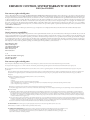
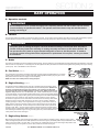
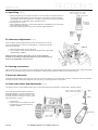
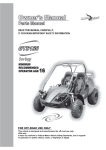
Book 2 of 2
K
BLAC
BLUE
E
WHIT
s
Curntitroller
o
C g
Plu
N
GREE
BF1
RED
E
WHIT
K
BLAC
K
BLAC
RED
r
BLUE
BLUE e/Regen
Driv
rse
Revfeety
Sa itch
Sw
N
BLUE
GREE
OW
ard
Forwafety
S itch
Sw
YELL
BLUE
K
BLAC
HITE
ry
Battceharge
s
i
D icator
Ind
Fus e
BLUE
10A
ter
ome
nti
Pote
OW
YELL
acto
Cont
GREY
BLUE
N
BROW
K
BLAC
W
R
R
F/N/
ch
Swit
N
F
N
GREE
RED
MODEL 7151 / AGES 13+ / 39 MPH MAX SPEED
7151 150cc FUN KART OWNER’S MANUAL / PARTS GUIDE
15516R1
THIS VEHICLE IS FOR OFF-ROAD USE ONLY THIS VEHICLE IS NOT DESIGNED FOR USE ON RENTAL TRACKS OR RACING
BEFORE OPERATING THIS VEHICLE, THE OWNER AND EACH OPERATOR MUST UNDERSTAND THIS VEHICLE WAS NOT DESIGNED OR MANUFACTURED TO MEET SPECIFICATIONS FOR USE ON PUBLIC ROADS,
STREETS, HIGHWAYS AND THOROUGHFARES. THE OWNER AND EACH OPERATOR MUST READ AND UNDERSTAND ALL THE INSTRUCTIONS FOR PROPER ASSEMBLY AND SAFE OPERATION, AS WELL AS THE
INSTRUCTIONS CONCERNING THE ENGINE AND ALL OTHER PORTIONS OF THE VEHICLE. CHILDREN MUST BE 13+ YEARS OF AGE FOR THIS VEHICLE AND SUPERVISED BY AN ADULT AT ALL TIMES WHEN USING
THIS FUN KART. SPEED REDUCTION KITS ARE AVAILABLE FOR ALL VEHICLES. THIS VEHICLE IS NOT A TOY.
EMISSION CONTROL SYSTEM WARRANTY STATEMENT
FOR 150cc ENGINES
Your warranty rights and obligations
The U.S. Environmental Protection Agency and Geason Enterprises, LLC dba Geason Powersports (hereinafter “Geason Powersports”) are pleased to explain the emission
control system warranty on your 2013 Off-Road ATV. New off-road motor vehicles must be designed, built and equipped to meet U.S. EPA Federal anti-smog standards. Geason
Powersports must warrant the emission control system on your vehicle for 5,000 km, or at least 30 months, whichever comes first, provided that there has been no abuse, neglect
or improper maintenance of your vehicle. This ATV was designed to meet the emission standards for 10,000 km, or five years, whichever comes first. Your emission control
system may include parts such as the carburetor or fuel injection system, the ignition system, catalytic converter and engine computer, if it is equipped. Also included may be
hoses, belts, connectors and other emission-related assemblies. Where a warrantable condition exists, Geason Powersports will repair your vehicle at no cost to you, including
diagnosis, parts and labor. If an emission-related part on your vehicle is defective, the part will be repaired or replaced by Geason Powersports. This is your emission control
system DEFECTS WARRANTY.
NOTICE! Use of any Geason Powersports vehicle in any type of competitive event completely and absolutely voids this and all other warranties offered by Geason
Powersports.
Owner’s warranty responsibilities
As the vehicle owner, you are responsible for the performance of the required maintenance listed in your owner’s manual. Geason Powersports recommend that you retain all
receipts covering maintenance on your vehicle, but Geason Powersports cannot deny warranty solely for the lack of receipts or for your failure to ensure the performance of all
scheduled maintenance. You are responsible for presenting your vehicle to the Geason Powersports dealer as soon as a problem exists. The warranty repairs should be completed
in a reasonable amount of time, not to exceed 30 days. As the vehicle owner, you should be aware that Geason Powersports may deny your warranty coverage if your vehicle or a
part has failed due to abuse, neglect, improper maintenance or unapproved modifications. If you use your vehicle in any type of competitive event, this warranty is immediately
and completely void. If you have any questions regarding your warranty rights and responsibilities, you should contact:
Geason Enterprises, LLC
dba Geason Powersports
1200 Lakeside Parkway #400
Flower Mound, TX 75028
Phone: 214-513-1700
Fax: 214-513-1711
or the
U.S. Environmental Protection Agency
2000 Traverwood Drive
Ann Arbor, MI 48105
Your warranty rights and obligations
Geason Enterprises, LLC dba Geason Powersports (hereinafter “Geason Powersports”) warrants that each new 2013 and later Geason Powersports off-road vehicle:
A. is designed, built and equipped so as to conform at the time of initial retail purchase with all applicable regulations of the United States Environmental Protection Agency, and;
B. is free from defects in material and workmanship which cause such vehicle to fail to conform to applicable regulations of the United States Environmental Protection Agency for the periods
specified above.
I. Coverage. Warranty defects shall be remedied during customary business hours at any authorized Geason Powersports dealer located within the United States of America in compliance with
the Clean Air Act and applicable regulations of the United States Environmental Protection Agency. Any part or parts replaced under this warranty shall become the property of Geason
Powersports.
II. Limitations This Emission Control System Warranty shall not cover any of the following:
A: Repair or replacement as a result of
(1) accident,
(2) misuse,
(3) repairs improperly performed or replacements improperly installed,
(4) use of replacement parts or accessories not conforming to specifications set forth by Geason Powersports, which adversely affect performance and/or
(5) use in competitive racing or related events.
B: Inspections, replacement of parts and other services and adjustments required for required maintenance.
C: Any vehicle equipped with an odometer or hour meter on which the odometer mileage or hour meter reading has been changed so that actual mileage cannot be readily determined.
III. Limited Liability
A. The liability of Geason Powersports under this Emission Control System Warranty is limited solely to the remedying of defects in material or workmanship by an authorized Geason
Powersports dealer at its place of business during customary business hours. This warranty does not cover inconvenience or loss of use of the vehicle or transportation of the vehicle to or
from the Geason Powersports. Geason Powersports shall not be liable for any other expenses, loss or damage, whether direct, incidental, consequential or exemplary arising in connection
with the sale or use of or inability to use the Geason Powersports vehicle for any purpose. Some states do not allow the exclusion or limitation of any incidental or consequential damages,
so the above limitations may not apply to you.
B. No express emission control system warranty is given by Geason Powersports, except as specifically set forth herein. Any emission control system warranty implied by law, including any
warranty of mechanability or fitness for a particular purpose, is limited to the express emission control system warranty terms stated in this warranty. The foregoing statements of warranty
are exclusive and in lieu of all other remedies. Some states do not allow limitations on how long an implied warranty lasts, so the above limitations may not apply to you.
C. No dealer is authorized to modify this Limited Emission Control System Warranty issued by Geason Powersports.
IV. LEGAL RIGHTS. This warranty gives you specific legal rights, and you may also have other rights which vary from state to state.
V. This warranty is in addition to the Geason Powersports limited vehicle warranty.
VI. ADDITIONAL INFORMATION. Any replacement part that is equivalent in performance and durability may be used in the performance of any
maintenance or repairs. However, Geason Powersports are not liable for these parts. The owner is responsible for the performance of all
required maintenance. Such maintenance may be performed at a service establishment or by any individual. The warranty period begins on the
date the ATV is delivered to an ultimate purchaser.
i
limited warranty
American SportWorks (hereinafter referred to as “ASW”) hereby warrants to the original purchaser that the frame components of new ASW fun karts will be
free from defects in material and workmanship. The period of warranty is thirty (30) days from date of purchase for the component parts (except as noted
below), ninety (90) days from the date of purchase for the frame, and one (1) year from date of purchase on select engines. Some engines may carry a separate
manufacturer’s warranty and are not covered by this ASW warranty. ASW, if notified of a defect in material or workmanship during the period of warranty,
will repair or replace, at its option, defective parts at no charge, other than the reasonable cost for the transportation of the component(s). ASW will also agree
to pay reasonable charges for labor, if necessary, to perform a warranty repair. Proof of Purchase must be provided to an approved ASW service center before
any warranty work is performed.
The original purchaser must operate the vehicle and maintain the vehicle in accordance with the instructions provided in the Operator’s Manual, the
supplements hereto, and labels affixed to the vehicle. Additionally, within (10) days of the discovery of an alleged defect, the original purchaser must contact
ASW’s Customer Service Department at 1-800-643-7332, 4404 Engle Ridge Drive, Fort Wayne, IN 46804 or via the internet at www.amsportworks.com.
The repair or replacement of any part or parts under this Limited Warranty shall not extend the term of the warranty beyond the original term as set forth
above.
General Exclusions: This limited warranty does not cover component failure or damage caused by any of the following: abnormal strain or stress, neglect;
abuse; improper assembly of components which were supplied in the factory sealed carton after the vehicle left ASW; improper maintenance, improper use of
the vehicle, including, but not limited to racing, jumping, stunt driving, or any other uses prohibited by the Operator’s Manual. Additionally, this warranty
does not cover component failure or damage to vehicles which are leased or rented, or vehicles which are used at a concession track.
Specific Exclusions: This limited warranty does not apply to components, which are subject to normal wear and tear. These items include, but are not limited
to, the tires, brakes, throttle, shift and brake cables, drive belt, the torque converter system, chain, seat, lights, fasteners, decals, or cosmetic body panels and
natural discoloration of material due to ultraviolet light. Downtime, pick-up and delivery charges are not covered by this warranty. This warranty does not
apply to select engines covered by a separate manufacturer’s warranty.
ASW MAKES NO OTHER WARRANTY OF ANY KIND, EXPRESSED OR IMPLIED. ALL WARRANTIES OF MERCHANTABILITY AND
FITNESS FOR A PARTICULAR PURPOSE WHICH EXCEED THE OBLIGATIONS AND TIME LIMITATIONS SPECIFIED IN THE
WARRANTY ABOVE ARE HEREBY DISCLAIMED BY ASW AND EXCLUDED FROM THIS WARRANTY. ADDITIONALLY, THIS WARRANTY
EXCLUDES ANY INCIDENTAL OR CONSEQUENTIAL DAMAGES, INCLUDING BUT NOT LIMITED TO LOSS OF USE. SOME STATES
DO NOT ALLOW A MANUFACTURER TO EXCLUDE OR LIMIT INCIDENTAL OR CONSEQUENTIAL DAMAGES AND, THEREFORE,
THE ABOVE EXCLUSION MAY NOT APPLY TO YOU.
SOME STATES DO NOT ALLOW LIMITATIONS ON HOW LONG AN IMPLIED WARRANTY WILL LAST. IT IS POSSIBLE THAT THE
ABOVE LIMITATION MAY NOT APPL Y TO YOU. THIS WARRANTY GIVES YOU SPECIFIC LEGAL RIGHTS, AND YOU MAY ALSO HAVE
OTHER LEGAL RIGHTS, WHICH VARY, FROM STATE TO STATE.
VEHICLE IDENTIFICATION NUMBER
Record the Vehicle Identification Number (VIN) and Model number of your American SportWorks Fun Kart
below for service and insurance records. The VIN can be found on the crossbar, behind the seat. The
Model number is located on the SKU decal near the floorboard.
VIN
MODEL
ii
TABLE OF CONTENTS
Emissions Warranty . . . . . . . . . . . . . . . . . . . . . . . . . . . . . . . . . . . . . . . . . . . . . . . . . . . . . . . . . . . . . . . . . . . . . i
ASW Limited Warranty . . . . . . . . . . . . . . . . . . . . . . . . . . . . . . . . . . . . . . . . . . . . . . . . . . . . . . . . . . . . . . . . . . . ii
SECTION 1 INTRODUCTION
Forward . . . . . . . . . . . . . . . . . . . . . . . . . . . . . . . . . . . . . . . . . . . . . . . . . . . . . . . . . . . . . . . . . . . . . . . . . . . . . . 1
Emissions Warranty . . . . . . . . . . . . . . . . . . . . . . . . . . . . . . . . . . . . . . . . . . . . . . . . . . . . . . . . . . . . . . . . . . . . . 1
Cell Phone Use . . . . . . . . . . . . . . . . . . . . . . . . . . . . . . . . . . . . . . . . . . . . . . . . . . . . . . . . . . . . . . . . . . . . . . . . 1
SECTION 2 OPERATION
Kart Operation . . . . . . . . . . . . . . . . . . . . . . . . . . . . . . . . . . . . . . . . . . . . . . . . . . . . . . . . . . . . . . . . . . . . . . . . . 2
Kart Features and Locations . . . . . . . . . . . . . . . . . . . . . . . . . . . . . . . . . . . . . . . . . . . . . . . . . . . . . . . . . . . . . . 4
SECTION 3 SERVICE
Replacement Parts . . . . . . . . . . . . . . . . . . . . . . . . . . . . . . . . . . . . . . . . . . . . . . . . . . . . . . . . . . . . . . . . . . . . . 5
Air Cleaner . . . . . . . . . . . . . . . . . . . . . . . . . . . . . . . . . . . . . . . . . . . . . . . . . . . . . . . . . . . . . . . . . . . . . . . . . . . . 5
Engine lubrication . . . . . . . . . . . . . . . . . . . . . . . . . . . . . . . . . . . . . . . . . . . . . . . . . . . . . . . . . . . . . . . . . . . . . . 5
Spark Plug . . . . . . . . . . . . . . . . . . . . . . . . . . . . . . . . . . . . . . . . . . . . . . . . . . . . . . . . . . . . . . . . . . . . . . . . . . . . 6
Carburetor Adjustment . . . . . . . . . . . . . . . . . . . . . . . . . . . . . . . . . . . . . . . . . . . . . . . . . . . . . . . . . . . . . . . . . . . 6
Cleaning Instructions . . . . . . . . . . . . . . . . . . . . . . . . . . . . . . . . . . . . . . . . . . . . . . . . . . . . . . . . . . . . . . . . . . . . 6
General Lubrication . . . . . . . . . . . . . . . . . . . . . . . . . . . . . . . . . . . . . . . . . . . . . . . . . . . . . . . . . . . . . . . . . . . . . 6
Chain Lubrication & Adjustment . . . . . . . . . . . . . . . . . . . . . . . . . . . . . . . . . . . . . . . . . . . . . . . . . . . . . . . . . . . . 6
Shock Adjustment . . . . . . . . . . . . . . . . . . . . . . . . . . . . . . . . . . . . . . . . . . . . . . . . . . . . . . . . . . . . . . . . . . . . . . 7
Shifter Adjustment . . . . . . . . . . . . . . . . . . . . . . . . . . . . . . . . . . . . . . . . . . . . . . . . . . . . . . . . . . . . . . . . . . . . . . 7
Storage Instructions . . . . . . . . . . . . . . . . . . . . . . . . . . . . . . . . . . . . . . . . . . . . . . . . . . . . . . . . . . . . . . . . . . . . . 7
SECTION 4 MAINTENANCE
Wheel Replacement . . . . . . . . . . . . . . . . . . . . . . . . . . . . . . . . . . . . . . . . . . . . . . . . . . . . . . . . . . . . . . . . . . . . 8
Front Wheel Alignment . . . . . . . . . . . . . . . . . . . . . . . . . . . . . . . . . . . . . . . . . . . . . . . . . . . . . . . . . . . . . . . . . . 8
Optional Speed Reducer installation . . . . . . . . . . . . . . . . . . . . . . . . . . . . . . . . . . . . . . . . . . . . . . . . . . . . . . . . 8
Specifications and Electrical Schematic . . . . . . . . . . . . . . . . . . . . . . . . . . . . . . . . . . . . . . . . . . . . . . . . . . . . . 9
SECTION 5 ILLUSTRATED PARTS LIST
Cylinder Head Assembly . . . . . . . . . . . . . . . . . . . . . . . . . . . . . . . . . . . . . . . . . . . . . . . . . . . . . . . . . . . . . . . . . 10
Cylinder . . . . . . . . . . . . . . . . . . . . . . . . . . . . . . . . . . . . . . . . . . . . . . . . . . . . . . . . . . . . . . . . . . . . . . . . . . . . . . 11
Engine Crankcase . . . . . . . . . . . . . . . . . . . . . . . . . . . . . . . . . . . . . . . . . . . . . . . . . . . . . . . . . . . . . . . . . . . . . . 12
Transmission . . . . . . . . . . . . . . . . . . . . . . . . . . . . . . . . . . . . . . . . . . . . . . . . . . . . . . . . . . . . . . . . . . . . . . . . . . 13
CVT Cover . . . . . . . . . . . . . . . . . . . . . . . . . . . . . . . . . . . . . . . . . . . . . . . . . . . . . . . . . . . . . . . . . . . . . . . . . . . . 14
Outer Crankcase Assembly . . . . . . . . . . . . . . . . . . . . . . . . . . . . . . . . . . . . . . . . . . . . . . . . . . . . . . . . . . . . . . . 15
Piston, Crank & Connecting Rod . . . . . . . . . . . . . . . . . . . . . . . . . . . . . . . . . . . . . . . . . . . . . . . . . . . . . . . . . . . 16
Camshaft Assembly . . . . . . . . . . . . . . . . . . . . . . . . . . . . . . . . . . . . . . . . . . . . . . . . . . . . . . . . . . . . . . . . . . . . . 17
Oil Pump Assembly . . . . . . . . . . . . . . . . . . . . . . . . . . . . . . . . . . . . . . . . . . . . . . . . . . . . . . . . . . . . . . . . . . . . . 18
Driven Pulley & Clutch . . . . . . . . . . . . . . . . . . . . . . . . . . . . . . . . . . . . . . . . . . . . . . . . . . . . . . . . . . . . . . . . . . . 19
Engine Electrical . . . . . . . . . . . . . . . . . . . . . . . . . . . . . . . . . . . . . . . . . . . . . . . . . . . . . . . . . . . . . . . . . . . . . . . 20
Electric Start . . . . . . . . . . . . . . . . . . . . . . . . . . . . . . . . . . . . . . . . . . . . . . . . . . . . . . . . . . . . . . . . . . . . . . . . . . 21
Driver Pulley . . . . . . . . . . . . . . . . . . . . . . . . . . . . . . . . . . . . . . . . . . . . . . . . . . . . . . . . . . . . . . . . . . . . . . . . . . 22
Fan Cover & Shroud Assembly . . . . . . . . . . . . . . . . . . . . . . . . . . . . . . . . . . . . . . . . . . . . . . . . . . . . . . . . . . . . 23
Carburetor . . . . . . . . . . . . . . . . . . . . . . . . . . . . . . . . . . . . . . . . . . . . . . . . . . . . . . . . . . . . . . . . . . . . . . . . . . . . 24
Frame Warning Labels . . . . . . . . . . . . . . . . . . . . . . . . . . . . . . . . . . . . . . . . . . . . . . . . . . . . . . . . . . . . . . . . . . . 25
Frame Group . . . . . . . . . . . . . . . . . . . . . . . . . . . . . . . . . . . . . . . . . . . . . . . . . . . . . . . . . . . . . . . . . . . . . . . . . . 26, 27
Steering & Brakes . . . . . . . . . . . . . . . . . . . . . . . . . . . . . . . . . . . . . . . . . . . . . . . . . . . . . . . . . . . . . . . . . . . . . . 28
Front Suspension . . . . . . . . . . . . . . . . . . . . . . . . . . . . . . . . . . . . . . . . . . . . . . . . . . . . . . . . . . . . . . . . . . . . . . . 29
Rear Swingarm Assembly . . . . . . . . . . . . . . . . . . . . . . . . . . . . . . . . . . . . . . . . . . . . . . . . . . . . . . . . . . . . . . . . 30
Engine / Muffler / Air Cleaner . . . . . . . . . . . . . . . . . . . . . . . . . . . . . . . . . . . . . . . . . . . . . . . . . . . . . . . . . . . . . . 31
Rear Axle . . . . . . . . . . . . . . . . . . . . . . . . . . . . . . . . . . . . . . . . . . . . . . . . . . . . . . . . . . . . . . . . . . . . . . . . . . . . . 32
Electrical . . . . . . . . . . . . . . . . . . . . . . . . . . . . . . . . . . . . . . . . . . . . . . . . . . . . . . . . . . . . . . . . . . . . . . . . . . . . . 33
15516R1
7151 OWNERS MANUAL / ILLUSTRATED PARTS LIST
iii
SECTION 1&2
introduction / safety
FORWARD
Your vehicle has been supplied with:
• OPERATOR SAFETY MANUAL (Book 1)
• OWNERS MANUAL / PARTS GUIDE (Book 2)
• KART SAFETY DVD
Congratulations on the purchase of your American
SportWorks / ASW Fun Kart. Please take a few moments
to get well acquainted with your vehicle by reading the
Operator Safety Manual as well as this Owners Manual /
Parts Guide. Before operating this vehicle, the owner,
and each operator, must understand that this vehicle was
not designed or manufactured to meet specifications for
use on public roads, streets, highways and thoroughfares.
The owner, operator(s) and passenger(s) must read and
understand all the instructions for proper assembly and
safe operation, as well as the instructions concerning the
engine and all other portions of the vehicle as described
and illustrated in this manual, the Operator Safety Manual
and on the included Kart Safety DVD. Children must be 13
years of age or older and supervised by an adult at all times
when using the vehicle. This vehicle is not a toy.
If any of these items are missing or were not
supplied with your vehicle, please contact
American SportWorks at 800-643-7332 or visit
our website at www.amsportworks.com.
Be sure to follow the recommended maintenance schedule
and service your machine accordingly.
Preventative
maintenance is extremely important to the safe operation
and longevity of your vehicle.
Inexperienced and first time drivers are urged to seek
instruction from a dealer or qualified instructor before and
during the initial use of this vehicle. It is also recommended
to practice in a large open area to become familiar with
the operation of the machine. This vehicle is designed for
drivers and riders 13 years and older.
For more information on American Sportworks and its
products visit our website at www.amsportworks.com.
New Vehicle Limited Warranty
For a detailed description of warranty coverage for your
vehicle, refer to the Warranty section of the Owners Manual
/ Parts Guide as supplied with the vehicle, or go to www.
amsportworks.com.
Emissions Warranty
For a detailed description of the emissions warranty for
your vehicle, refer to the Emissions Warranty section of the
Owners Manual / Parts Guide as supplied with the vehicle,
or go to www.amsportworks.com.
Cell Phone Use
The use of Mobile Communications Equipment has become
increasingly important and prevalent in both personal
and business affairs. Drivers must not compromise their
own, or others safety when using such equipment. ASW
recommends against the use of any handheld device while
driving this vehicle.
We hope you will have a fun, safe experience with our
products and thank you again for choosing an American
SportWorks Fun Machine.
1
safety section
SOME WORDS ABOUT SAFETY
Please thoroughly read and understand the Safety
Section outlined in the Operator Safety Manual supplied
with this Fun Kart along with the Kart Safety DVD. If,
for some reason, you did not receive these items please
contact American Sportworks or visit our website at www.
amsportworks.com.
WARNINGS AND CAUTIONS
! This is the safety alert symbol. When you see this
symbol on your machine or in this manual, be alert to the
potential for personal injury.
Read and follow all instructions in the Operator Safety
Manual, this manual and any accompanying manuals
before attempting to operate this vehicle. Make sure to
view the Kart Safety DVD.
!
WARNING
Indicates a potential hazard that could result in
severe personal injury or death
!
CAUTION
Indicates a potential hazard which may result in
personal injury or damage to the machine.
NOTE: Use of the word “NOTE” will alert you to key
information or instructions.
7151 OWNERS MANUAL / ILLUSTRATED PARTS LIST
15516R1
SECTION 2
operation
KART OPERATION
A. Operation controls
!
WARNING
Do not attempt to start or operate the engine until completely familiar with the location and use of each
control necessary to operate this vehicle. The operator must know how to stop this machine before
starting and driving it.
B. Throttle
The right foot pedal is the throttle and controls the speed of the kart. As the engine speed increases above idle, the driver pulley automatically engages
the drive belt and moves the vehicle forward. To disengage the driver pulley at any time, allow the throttle to return to the idle position.
!
WARNING
Every time, prior to starting the engine, check the throttle assembly to ensure that when the pedal is
pushed all the way forward the assembly is working smoothly and returns to idle when released. Do
not operate this unit if pedal or engine throttle linkage fail to return to the idle position. If unable to
correct the problem through lubrication, adjustment or replacement of worn parts, contact your dealer
for assistance.
C. Brake
The brake is controlled by the left foot pedal (See Figure below). Applying pressure to the pedal draws the brake pads against the brake disc at the rear
axle and slows or stops the kart. The locking lever can be applied to act as a park brake and should remain applied during starting and engine warming
(choke cycle). See I. Park Brake for more instruction.
D. Fuel Valve
ON
(see fig. D1)
OFF
The manual valve is mounted to the bottom of the fuel tank and provides the added feature of a “reserve”
position which provides access to a reserve fuel supply allowing additional driving range to get to a fuel
filling station should the main fuel supply be used completely.
NOTE: Turn fuel valve to OFF position during transport
E. Engine Starting
RESERVE
fuel valve in
“OFF” position
fig. D1
(see fig. E1)
For parental control and added security, this unit is equipped with a keyed ignition switch.
To start the unit, ensure both Engine Stop Switches are in the RUN position. (NOTE: Your
Fun-Kart is equipped with (2) engine stop switches, one located on the dash and
one located on the swing arm. BOTH switches must be in the “RUN” position for the
engine to start.) Place the unit in the NEUTRAL gear. Fasten seatbelt and place one foot
on the brake pedal. Pump the throttle pedal several times to ensure that the pedal operates
and returns smoothly. Apply choke by pulling out and holding the choke cable located under
the driver’s seat. Turn ignition key fully clockwise and hold to start the engine. (Caution:
Do not let the engine turn over for more than 5 seconds at a time as this may cause starter
damage). Once the engine starts, allow the key to return to the run position. Adjust the
choke by pushing it in slowly. If the engine starts to run rough, pull the choke control out
slightly and then continue to push the choke control in after the engine can accept small
applications of the gas pedal. Continue this process until the choke control is pushed all
the way in (fully “OFF”). This may require a period of several seconds to several minutes,
depending on the air temperature. Before driving this vehicle, test that the ignition switch will
turn off the engine. With the engine running, turn the ignition key counter-clockwise to the
fig. E1
“OFF” position to shut down the engine.
F. Engine Stop Switch
(see fig. F1)
SWINGARM MOUNTED
ENGINE STOP
SWITCH
= RUN
Before driving this vehicle, test each Engine Stop Switch to ensure that it is operating properly. With the engine running, DASH MOUNTED
ENGINE STOP
switch the Engine Stop Switch to the STOP position to shut down the engine. (The STOP position may be identified on the
SWITCH
switch by the word “STOP”, the word “OFF”, or the symbol “O”.) Repeat the process for the other Engine Stop Switch. With
the engine running, turn the ignition key to the “OFF” position to shut down the engine.
OUT=RUN
15516R1
7151 OWNERS MANUAL / ILLUSTRATED PARTS LIST
= STOP
IN=STOP
fig. F1
2
SECTION 2
operation
G. Seat Adjustment
The unit is equipped with an adjustable driver’s seat. To adjust, lift the lever just in front of the seat bottom and move the seat either forward or
backward. Release the lever at the desired seat location, ensuring that it snaps back into place to lock the seat in position.
!
WARNING
Never operate this vehicle when the seat is not securely locked into position. Serious injury or death
could occur due to loss of control. Always make seat adjustments with the vehicle fully stopped and
the engine shut off.
H. Occupant Restraints
This kart is equipped with 3 point retracting seat belts. Insert the metal tongue into the buckle until it is securely attached. Final adjustments should be
made with the plastic tension stop such that the belt is against the shoulder and chest with no excess slack.
!
WARNING
Operating this kart without your seat belt could cause you to be thrown from the kart, causing serious
injury or death.
I. Rear Cargo Rack
This kart is equipped with a rear cargo rack. The rack should be used for transporting small items, however, all items MUST be securely tied down with
adequate straps or cords. Additionally, never exceed the rated load of 25lbs.
!
WARNING
Failure to properly tie down loose items and exceeding the maximum rating of the cargo rack may
cause serious injury or death.
J. Gear Selection
This kart is equipped with a Drive / Neutral / Reverse transmission. To shift gears, bring the kart to a complete stop and let the engine RPM drop to the
idle level. Move the shift lever to the desired gear and gently depress the throttle pedal.
!
CAUTION
Damage to the fun kart will occur if the unit is shifted into a different gear while the kart is still in
motion. ALWAYS bring the vehicle to a complete stop before selecting a different gear.
K. Steering Adjustment
(see fig. K1)
This kart is equipped with an adjustable tilt steering feature. To adjust, loosen the adjusting
knob (A) until the steering column can move up and down. Select the appropriate setting
and re-tighten the adjusting knob.
fig. K1
!
WARNING
Do not operate the vehicle without ensuring that the steering adjustment knob is securely tightened.
Serious injury or death could occur due to loss of control or rollover.
3
7151 OWNERS MANUAL / ILLUSTRATED PARTS LIST
15516R1
SECTION 2
operation
L. Park Brake
(see fig. L1)
The park brake should be applied during starting, engine warming (choke cycle), and anytime the vehicle is parked and/or left unattended. The park
brake is set by applying pressure to the brake pedal and latching the locking lever over the latch pin.
To apply the park brake
fig. L1
Brake pedal
Latch Pin
Locking Lever
Latch Pin
Brake pedal
Locking Lever
Parking brake not engaged
Parking brake engaged
KART FEATURES AND LOCATIONS
Cargo Rack
Rear View Mirror
Fuel Tank
Steering Wheel
Speedometer
Fuel Valve
Air Filter
Shifter
Manual Choke
!
CAUTION
NEVER use E-15 or E-85 fuel or blends with Ethanol content in excess of 10%. Ethanol blends in excess of 10%
will cause damage to the engine and void manufacturer warranty
a. Use regular unleaded 87 octane gasoline with up to a 10% ethanol blend.
b. This engine supplied with this Fun-Kart is NOT designed for Flex Fuel operation.
15516R1
7151 OWNERS MANUAL / ILLUSTRATED PARTS LIST
4
SECTION 3
service
REPLACEMENT PARTS AND SERVICE
Most replacement parts are typically available from your dealer. Because of immediate availability and convenience, it is recommended that replacement
parts be ordered from an authorized dealer. Take this manual and all supplements to the dealer when ordering parts in person.
If replacement parts are not available from a dealer, they may be ordered directly from American Sportworks by contacting ASW at 1-800-643-7332 or
online at www.amsportworks.com. Orders may be subject to a minimum fee. A listing of authorized service center locations in your area is also available
from our Customer Service department.
Record the Vehicle Identification Number (VIN) in the spaces provided at the front of this manual. The VIN can be found on the crossbar, behind the seat.
SERVICE
A. Air Cleaner
(see fig. A1)
This unit is equipped with a paper style air filter element and should be replaced after every 20 hours of
operation (Ref Figure).
NOTE: Operation in unusually dusty conditions may require more frequent replacement.
1)
2)
3)
4)
5)
Remove the air cleaner cover (1) by removing the Phillips head screws.
Clean any excess dirt, oil, or dust from the air cleaner box with a mild detergent and water
solution.
Thoroughly dry the air box
Replace the air cleaner element (2)
Carefully align the gasket between the air box halves during re-assembly
B. Engine Lubrication
fig. A1
(see fig. B1)
You MUST change the oil in the crankcase after the first 5 hours of operating a new engine. The engine oil should then be changed every 20 hours of
use thereafter. This will insure proper lubrication of the internal parts and prevent costly repairs due to excessive wear.
!
CAUTION
This unit has been shipped with special BREAK-IN oil pre-filled in the engine crankcase. This oil MUST
be changed after 5 hours of operation. Replace with SAE 10W40 weight motor oil as described in the
following section.
!
WARNING
THINK
GREEN
Used oil MUST be disposed of at a proper collection center
a. Remove the drain plug located on the bottom of the right rear side of engine. Elevating the front of the kart slightly will help drain all of the oil.
b. The oil should be emptied into suitable container for recycling.
c. Remove and clean the oil screen.
d. With the oil completely drained, replace the drain plug and tighten securely.
e. Place the kart back onto a flat surface to level the engine, and Re-fill the crankcase with 30oz of SAE 10W40 motor oil.
f. Check the oil level using the dipstick attached to the oil plug cap. Be sure to check the oil level before each use of the kart. Add oil when necessary to keep the oil level between the bottom of the dipstick and the “O” mark.
NOTE: Oil level should be checked by dipping the oil level stick into the crankcase
WITHOUT screwing the cap in.
5
fig. B1
7151 OWNERS MANUAL / ILLUSTRATED PARTS LIST
15516R1
SECTION 3
service
C. Spark Plug
(see fig. C1)
a. Remove the spark plug and inspect it each time you change the oil (Use a spark plug wrench). The electrodes should be kept clean and free of carbon. The presence of carbon or excess oil will greatly reduce engine performance. If possible, check the spark plug gap (area between the electrodes) using a wire feeler gage or spark plug gap tool.
b. Correct gap is 0.6 - .07mm
c. Before installing the spark plug, coat the threads lightly with graphite lubricant to ensure easier removal of the plug in the future.
d. Spark plug should be replaced once a year for optimum engine performance.
fig. C1
D. Carburetor Adjustment
(see fig. D1)
All the necessary carburetor adjustments have been made at the factory, and the
recommended settings are correct for most applications. To adjust the engine idle
setting on the carburetor:
a. Allow the engine to warm up for 5-10minutes
b. Using a Phillips screwdriver, adjust the idle screw (B) until the engine settles at approximately 1400RPM
NOTE: For further carburetor adjustments, refer to the Service Manual
available on our website at www.amsportworks.com, for purchase from your
Dealer or by calling ASW’s customer service.
fig. D1
E. Cleaning Instructions
Keep your kart clean by using a clean rag and a mild detergent and water solution. Wipe off all dirt and oil from around the controls. Wipe off any spilled
fuel and oil. Keep the engine clean and clear of foreign objects, especially those around the air intake fan and air inlet ductwork.
F. General Lubrication
Lubricate the vehicle at least every 90 days, and more often, if the kart is used daily or in unusually dusty conditions. Lubrication of the front suspension
should be performed by adding fresh axle grease, with a grease gun, to the fittings located on each A-Arm.
G. Chain Lubrication and Adjustment
(see fig. G1)
For optimum chain life, regular lubrication with a spray on chain lubricant should be performed on a regular basis. (Ref Figure below)
A new chain will have initial stretch and therefore
will require adjustment. The first chain adjustment
should be made after the first 2 hours of use. If the
chain has more than ½” of slack or “flex” then it will
require adjustment. To adjust:
a. Loosen Nut (1).
b. Adjust nut (2) on the underside of the tube.
c. Re-tighten Nut (1) until the proper chain tension is achieved.
fig. G1
15516R1
7151 OWNERS MANUAL / ILLUSTRATED PARTS LIST
6
SECTION 3
H. Adjustment of Front and Rear Shock
service
(see fig. H1)
There are five adjustable positions on each shock. The center notch is the default
position as set by the manufacturer (Ref Figure). Use a round nut wrench to adjust the
shock.
To INCREASE the shock stiffness, rotate the ring to the highest (longest) setting.
To DECREASE the shock stiffness, rotate the ring to the lowest (shortest) setting.
Shock stiffness adjustments should be made based on the overall weight of the rider
and occupant.
fig. H1
I. Shifter Adjustment
(see fig. I1)
Your unit may require an occasional adjustment in the shift cables due to typical
stretch found during normal operation of the kart. To make shift adjustments,
ensure that engine is off and spark plug cap is removed. Refer to the following
procedure:
a. Push the shift lever to the “D” position
b. Check the restriction control disc found just behind the oil level dipstick to
ensure that it has rotated forward all the way (looking for any slack in
control cable #1)
c. Loosen adjustment nuts #1 and #2, pulling the housing to draw the cable
tight. Re-tighten the nuts when the cable is properly tensioned.
d. Shift the lever to the “R” position and check the control disc to ensure that
it has rotated full towards the rear of the kart.
e. Loosen adjustment nuts #3 and #4, pulling the cable housing to draw the
#2 control cable tight.
f. Re-tighten nuts #3 and #4 when the cable is properly tensioned.
fig. I1
J. Storage Instruction
If you plan to store (and not operate) your kart for a period in excess of 30 days, or at the end of each driving season, the unit should be set up for
storage as follows:
a. Drain fuel tank and carburetor by allowing the engine to run completely out of fuel.
b. Lubricate the engine cylinder by removing the air cleaner and spraying an engine fogging oil through the carburetor.
c. Do NOT save or store gasoline over the winter. Using old gasoline, which will deteriorate from storage, will make the engine difficult to start and
affect the performance of the engine.
d. Remove the battery from the unit and apply a periodic trickle charge to maintain the battery at a proper voltage level for the next riding season.
e. To protect the paint, plastics and upholstery, it is a good idea to keep the unit covered when not in use.
!
CAUTION
If this unit is stored outside, the air box could collect rainwater. To prevent water from damaging the
engine, any trapped water should be drained prior to each use by opening the drain tube located on the
bottom side of the air box.
7
7151 OWNERS MANUAL / ILLUSTRATED PARTS LIST
15516R1
SECTION 4
maintenance
GENERAL MAINTENANCE
A. Front Wheel Replacement
(see fig. A1)
Do not disassemble the castle nuts when you replace the front wheels. It is only
necessary to remove the 4 lug nuts to remove the wheel. (See Figure)
Tighten the nuts securely after replacing the wheels.
B. Rear Wheel Replacement
(see fig. A1)
Do not disassemble the castle nuts when you replace the rear wheels. It is only
necessary to remove the 4 lug nuts to remove the wheel. (See Figure)
Tighten the nuts after replacing the wheels.
fig. A1
C. Front Wheel Alignment
(see fig. C1)
The front wheels should be set with a “toe-in” from 1/8” to 1/4”. At the centerline of the tires,
measure the Distance A and the Distance B. For proper toe adjustment, Dimension A should
be 1/8” – 1/4” greater than Dimension B.
To make adjustments:
a. Loosen the lock nuts on both sides of Front Tie Rods.
b. Ensure the steering wheel is centered, and adjust Dimension B by equally rotating the
tie rods in or out with a 12mm wrench.
c. After adjusting to the desired length, tighten the lock nut against the rod end.
d. Recheck the dimensions for proper alignment.
D. Optional Speed Reduction Installation
(see fig. D1)
This kart has been equipped with provision for a speed limiter to reduce the overall speed
of the unit to 20mph max. This kit is available from your dealer or directly from American
SportWorks by calling customer service.
To install the speed limiter:
a. Remove the electrical control box cover located on the rear swing arm, just next to
the air box, using a Phillips screwdriver.
b. Locate the CDI (black box with 2 wire plugs)
c. Unplug the old CDI and replace with the new Rev Limited CDI provided in the kit.
d. Replace the electrical box cover, being careful not to damage or crush any wires
and connections.
A
WHEEL TIE ROD
NOTE: Keep the original CDI so that the kart can be changed back
to the original factory setting if desired.
CL
CL
B
fig. C1 Toe Adjustment Diagram
!
CAUTION
Prevailing torque type locknuts must be replaced with
new after the old locknuts are removed.
fig. D1
15516R1
7151 OWNERS MANUAL / ILLUSTRATED PARTS LIST
8
SECTION 4
maintenance
7151 SPECIFICATIONS
ENGINE
Type
Power (BHP @ RPM)
Torque (Ft-lbs @ RPM)
Starting System
Air Filtration
Exhaust System
Fuel Capacity
Oil Capacity
Spark Plug
Single Cylinder, 150cc, Air Cooled, 4 cycle
≈ 9.0 @ 7500
≈ 13.0 @ 5500
Keyed Electric / CDI
Single Element
Muffler with Heat Shield
1.75 gal
30 oz. 10W40
NGK C7HSA
TRANSMISSION
Type: Dual Wheel Drive
CVT Automatic with Reverse
#50 5/8” Pitch
CHAIN SIZE
TIRES & WHEELS
Front
Rear
17 x 7 - 8 @ 15 p.s.i.
18 x 9.5 - 8 @ 15 p.s.i.
ADVANCED GEOMETRY SUSPENSION
Front
Rear
Double A-Arm with Adjustable Coil Over Damped Shocks
Swing Arm with Adjustable Coil Over Damped Shocks
STEERING
Type:
Rack and Pinion
FRAME
Type - Heavy Gauge - Jig Welded
Rear Axle
Finish
BRAKES
Type: Rear
8.75” Hydraulic Disc with Parking Brake
PERFORMANCE
Max Speed Approx.
Fuel Consumption
Up to 39 mph (optional speed reducer available - 20 mph)
Up to 50 mpg
SPECIAL FEATURES
Adjustable slide bucket driver seat, fixed bucket passenger seat, 3 point shoulder/lap belts
with retractor, dual engine stop switch, 1-1/4" full brush bars, steerable front fenders, rear
fenders, dual quartz halogen running lights, rear cargo rack, rear view mirror, speedometer,
odometer, tilt wheel steering, plastic hood, whip flag, compliant to ASTM F2011.
*20 mph speed reduction kit available (P/N 14573). Available mesh sun top.
DIMENSIONS
Curb Weight
Maximum Rider Weight
Seat To Pedals
Wheelbase
Vehicle - Overall
Climbing Angle
475 lbs.
400 lbs.
34” - 39”
57”
83.2”L x 53.4”W x 53.75”H
20 - 25º
Battery
7151 ELECTRICAL SCHEMATIC
Starter Relay
G
Headlamp
12V / 25W
(Select Models)
Stop Switch
Detail
NC
NO
C
G
B/W
BR
B
BR
G
Stop Switch
Dash
G
L/W
Stop Switch
Engine
L/W
G
R
3
Fuse (2) 15A
R
R
Headlamp
12V / 25W
(Select Models)
B
Y/R
BR
G
B/Y
Wire Color Chart
9
P
BR
O
SB
LG
GR
B
G
G
Pink
Brown
Orange
Lt Blue
Lt Green
Gray
Y/R
R
2
B
Y
L
G
R
W
R
R
B
Ignition Switch 1
Black
Yellow
Blue
Green
Red
White
Starter
BR
Light Switch
(Select Models)
Light Switch
Detail
1.25” Main Frame
1.25” Hardened Alloy Steel
Baked Powder Coat
B/Y
L/Y
G
P
R
Y
G
Y
P
L/Y
G
Y
G
Resistor
10W 10W
Ignition Coil
CDI
7151 OWNERS MANUAL / ILLUSTRATED PARTS LIST
Voltage
Regulator
Generator
Auto Choke
15516R1