1
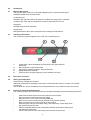
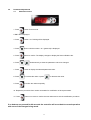
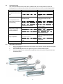
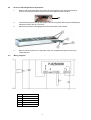
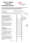
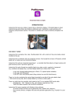
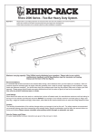
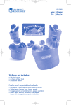
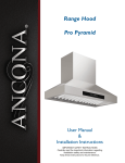
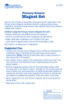
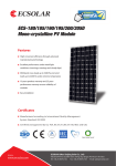
PREP TOP
Service Manual
PT 142H. PT 162H. PT182H. PT212H
PT128H. PT148H. PT168T. PT188H. PT218H.
PREP TOP
CONTENTS
1.
Dimensions
2
2.0
Introduction
2.1
Machine Description
3
2.2
Operating Instructions
3
2.3
Basic User Functions
3
2.4
Setting the Temperature
3
2.5
Defrosting and Routine Maintenance
3
3.0
Controller Adjustments
4
3.1
Parameter Access
4
3.2
Parameter Settings
5
4.0
Trouble Shooting
6
5.0
Glass Fitting Instructions
6
6.0
Access to the Refrigeration Compartment
7
7.0
Wiring Diagram
7
1.0
Dimensions
Interior
Dimensions
Model
PT 128
PT 142 / 148
PT 162 / 168
Dimensions
758mm
958mm
Exterior
Dimensions
1158mm
Model
PT 128
PT 142 / 148
PT 162 / 168
PT 182 / 188
PT 182 / 188
2
Dimensions
1200
1400mm
1600mm
2.0
Introduction
21
Machine Description.
The prep top range consist of a horizontal refrigerating show case for the storage of
foodstuffs divided into three basic areas.
Condensing Unit.
Situated to the right hand side of the machine complete with compressor, condenser,
condenser fan motor and the refrigeration controls incorporated in the cover.
Evaporator.
Situated inside the foam insulation.
Storage Area.
Refrigerated well in which pans are placed for the storage of food products.
2.2
Operating Instructions.
The controls are grouped together in the cover of the condensing unit.
1.
2.
3.
4.
5.
On/off switch. When the appliance is switched on the green indicator
illuminates.
Defrost indicator. Set point decrease
Compressor operation indicator. Set point increase.
Digital temperature indicator.
Check set point. Programming key (not accessible to the user).
2.3
Basic User Functions.
2.4
Setting the temperature.
Press button 5 to display the set point.
Whilst the temperature is displayed, press button 2 to decrease the set point or button 3 to increase
the set point.
The set point can only be set between the preset parameters of 150C maximum and 00C minimum.
2.5
Defrosting and Routine Maintenance
The internal compartment must be defrosted and cleaned periodically as per the following instructions.
-
Switch the machine Off and remove the pans from the machine.
Disconnect the machine from the mains supply.
Allow all traces of ice to melt in the refrigerated well.
Remove any traces of food and other deposits using a plastic spatula.
Never use wire wool or scouring powder on any surface.
Wipe the interior using a warm damp soapy cloth followed by a clean damp cloth
Dry the well using a soft cloth.
Clean the stainless exterior with a proprietary stainless steel cleaner following the
manufacturers instructions.
Connect the machine to the mains supply and switch the machine On.
3
3.0
Parameter Adjustments
3.1
Parameter Access
1. Press
button for 5 seconds.
2.”PS” will be displayed
3. Press
button “ 00 ” blinking will be displayed.
4. Press
button until the number “ 22 “ (password) is displayed.
5. Press
button to confirm. The display changes to display the first modifiable code.
6. Press
simultaneously to show the parameter code to be changed.
7. Press
button to display the selected parameter value.
8. Press
to increase the value or press
9. Press
to confirm the value temporarily.
to decrease the value.
10. Repeat the procedure from number 6 onwards for modification of other parameters.
11. Press
button once more to confirm the new values and to exit the modification procedure.
If no buttons are pressed for 60 seconds the controller will revert back to normal operation
with none of the changes being saved.
4
2.2
Parameter Settings
Parameter Description
Title
PA
Password
Probe Parameters
/ C Calibration of Air Probe
/ 2 Reading Stability
/ 4 Display Probe
o
o
/5 C/ F
Temperature Parameters
rd Air Probe Differential
r1 Minimum Set Point
r2 Maximum Set Point
r3 Alarm Enabling During Defrost
r4 Automatic variation of set point with
curtain switch closed.
Compressor Parameters
dO Defrost Type
dI Time Interval between two defrosts
dt Defrost End Temperature
dP Maximum Defrost Duration
d4 Defrost After Switch On
d5 Delay Defrost After Switch On
d6 No Display During Defrost
dd Dripping Time
d8 Alarm Delay After Defrost
d9 Priority of the defrost over
Compressor Delays
d/ Defrost Probe Reading
dC Time Selection
Alarm Parameters
AO Alarms and Fans delta
AL Low Temperature Alarm
AH High Temperature Alarm
Ad Temperature Alarm Delay
A7 External Alarm Delay
Other Selections
HO Serial Address
H1 Alarm Relay Mode
H2 Buttons Disabled or Enabled
H4 Buzzer Disabled or Enabled
H5 Identification code for
programming key
T
External parameter programming
Range
Unit of
Measure
Setting
22
C / oF
0
4
0
Flag
0
C / oF
o
C / oF
o
C / oF
Flag
2
0
+15
0
Flag
3
0 = no, 1 = yes
Flag
Hour
o
C / oF
Minutes
Flag
Minutes
Flag
Minutes
Hour
2
0
4
1
0
0
0
0
0
0 = no, 1 = yes
Flag
0
C / oF
Flag
0
x 0,1 oC / oF
o
0 = Air Probe. 1 = Food Probe.
0 = oC, 1 = oF
Hysteresis
0 = no, 1 = yes
o
A4 = 4
0 = Electric. 1 = Hot Gas. 2 = Timed / Off Cycle
When Defrost Probe is Fitted
0 = hours, 1= minutes
o
o
AL = 0 excluded
AH = 0 excluded
0 = Alarm ON, Relay Energised
0 = Disabled. 1 = Enabled
1 = Enabled. 0 = Disabled.
C / oF
o
C / oF
o
C / oF
Minutes
Minutes
1
127
127
120
0
Flag
Flag
Flag
1
0
1
0
\\\
5
3.0
Trouble Shooting.
The causes of malfunctions are often due to problems that can be easily resolved. Check the
following points, according to the problem encountered, and carry out the corresponding operation.
Sympton
Possible Cause
Unit switched Off and On using
Refrigeration unit does not the On/Off Switch.
start.
No power supply.
Ambient to high.
The Compressor runs
continuously but does not
cool sufficiently.
Correction
The machine starts again in 3
Minutes.
Check plug, sockets, fuses and
power.
Ventilate the room or move any
heat sources away from the
machine
Dirty Condenser
Clean Condenser
Shortage of refrigerant
Check for leaks
Condenser fan stopped
Check electrical connections,
replace if faulty.
Replace controller.
Refrigeration compartment Faulty temperature controller
iced up, compressor
Temperature controller set to low Check parameter settings
running contiuously
Temerature sensor faulty
Replace faulty sensor
Persistent Vibration
Check that the machine does not
come into contact with any other
appliance.
Noisy in operation
Noise coming from unit compart- Fan blade catching on condenser
or pipework
ment
E1= Displayed
4.0
Temperature sensor faulty
Replace faulty sensor
Glass fitting instructions
1.
2.
3.
Screw the slotted glass supports to the top edge of the machine. Slot the side and rear glass
into the supports.
Connect the side glass to the rear glass using the two hole brackets supplied.
Place the top glass onto the side and rear glass and secure into place using the three hole
brackets supplied.
6
5.0
Access to the Refrigeration Compartment
1.
Remove the small plastic side covers from the control panel to gain access to the fixing
screws. Unscrew the screws and remove the control panel from the machine.
1
6.0
2.
Locate the fixing screw through the square hole in the top panel and unscrew it sufficiently to
release the tension but do not remove.
3.
Slide the top forward to disengage it from the screw and the rear retainer.
4.
Remove the two screws on the right side of the unit compartment to gain access to the
condensing unit.
Wiring Diagram
C
Compressor
IG On/ Off Switch
SC Temperature Probe
SL Mains On Light
TE Temperature Controller
VC Condenser Fan
7
A division of ITW Ltd
Foster Refrigerator
Oldmedow Road
Kings Lynn
Norfolk
PE 30 4JU
PT/SM/02/2003