1
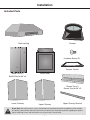
® Range Hood Pro Pyramid User Manual & Installation Instructions IMPORTANT SAFETY INSTRUCTIONS Carefully read the important information regarding installation safety and maintenance. Keep these instructions for future reference. Before You Begin INSTALLERS - Start Here Safety Instructions are on pages 4 and 5 and Installation Instructions are on pages 6 to 16. Please perform these steps: 1. Read the safety instructions. 2. Read all instructions in the Installation section of this manual BEFORE installing the range hood. 3. Remove all packing materials. 4. When finished, make sure to leave these instructions with the consumer. 5. Installation is only to be done by a qualified technician, but ultimately proper installation is the responsibility of the installer. 6. Product failure due to improper installation is not covered under the Warranty. CONSUMERS - Start Here Safety Instructions are on pages 4 and 5 and Operating Instructions are on pages 17 and 18. Please perform these steps: 1. Read the safety instructions. 2. Read all instructions in the manual BEFORE operating the range hood. 3. Remove all packing materials. 4. Installation is only to be done by a qualified technician, but ultimately proper installation is the responsibility of the installer. 5. Product failure due to improper installation is not covered under the Warranty. Screw Note: For safety reasons, screws and anchors for mounting will not be included due to the variation of cabinetry constructions and wall material. Please consult your installation specialist regarding the optimal type of mounting screws and wall anchors to suit your home’s construction. —2— Table of Contents Before You Begin................................................................................................................................ 2 Table of Contents............................................................................................................................... 3 Important Safety Information............................................................................................................. 4 Installation.......................................................................................................................................... 6 Included Parts.................................................................................................................................... 6 Range Dimensions............................................................................................................................. 7 Specifications..................................................................................................................................... 7 Step 1 - Read the Safety Instructions................................................................................................ 8 Step 2 - Unpack the Range Hood and Prepare Tools........................................................................ 8 Step 3 - Plan Desired Location.......................................................................................................... 8 Step 4 - Test Unit’s Functions............................................................................................................ 8 Step 5 - Figure Proper Venting........................................................................................................... 9 Step 6 - Put motor housing upside down on a flat surface............................................................. 10 Step 7a - Align main housing over motor body............................................................................... 10 Step 7b - Insert motor body inside main housing............................................................................ 11 Step 8 - Screw two sections............................................................................................................ 12 Step 9 - Connect the connectors..................................................................................................... 12 Step 10 - Mark Placement of Mounting Screws.............................................................................. 12 Step 11 - Place Hood on Mounting Screws.................................................................................... 13 Step 12 - Install Damper.................................................................................................................. 13 Step 13 - Install Ductwork............................................................................................................... 13 Step 14 - Install Lower Chimney...................................................................................................... 13 Step 15 - Install Bracket and Upper Chimney................................................................................. 14 Step 16 - Connect to AC................................................................................................................. 15 Step 17 - Install Grease Trays.......................................................................................................... 16 Step 18 - Install Baffle Filters........................................................................................................... 16 Operation......................................................................................................................................... 17 Using the Fan................................................................................................................................... 17 Turning the Light On or Off.............................................................................................................. 17 Replacing the Puck Light................................................................................................................. 18 Cleaning the Range Hood................................................................................................................ 18 Replacement Parts........................................................................................................................... 19 —3— Important Safety Information READ ALL INSTRUCTIONS BEFORE USE Read and follow all instructions before using the range hood to prevent the risk of fire, electric shock, personal injury, or damage when using the range hood or appliances with the range hood. This guide does not cover all possible conditions that may occur. Always contact your service technician or manufacturer about problems that you do not understand. • The installation in this manual is intended for qualified installers, service technicians or persons with similar qualified background. Installation must be done by qualified professionals and in accordance with all applicable codes and standards, including firerated construction. • The range hood may have very sharp edges; please wear protective gloves if it is necessary to remove any parts for installing, cleaning or servicing. To reduce the risk of fire, electric shock, or injury to persons: • For general ventilating use only. DO NOT use to exhaust hazardous or explosive materials and vapors. • Clean grease-laden surfaces frequently. To optimize performance and to disperse air properly, make sure to vent air outside. DO NOT vent exhaust into spaces between walls, crawl spaces, ceilings, attics or garages. • Ducted fans MUST always be vented to the outdoors. • Activating any switch ON before completing installation may cause damage or electric shock. • Due to the size of this range hood, two person installation is recommended. being switched on accidentally. When the service disconnecting means cannot be locked, securely fasten a prominent warning device, such as a tag, to the service panel. • This unit MUST be grounded and use only metal ductwork. • Sufficient air is needed for proper combustion and exhausting of gases through the duct to prevent back drafting. • When cutting or drilling into wall or ceiling, be careful not to damage electrical wiring or other hidden utilities. • All electrical wiring must be properly installed, insulated and grounded. • WARNING: To Reduce The Risk Of Fire Or Electric Shock, Do Not Use This Fan With Any Solid-State Speed Control Device. • Old duct work should be cleaned or replaced, if necessary to avoid the possibility of a grease fire. • The combustion air flow needed for safe operation of fuel-burning equipment may be affected by this unit’s operation. Follow the heating equipment manufacturer’s guideline and safety standards such as those published by the National Fire Protection Association (NFPA), and the American Society of Heating, Refrigeration and Air Conditioning Engineers (ASHRAE), and other local code authorities. • Check all joints on duct work to ensure proper connection and all joints should be properly taped. • Use this unit only in the manner intended by the manufacturer. If you have questions, contact the vendor. READ AND SAVE THESE INSTRUCTIONS • Before servicing or cleaning the unit, switch power off at service panel and lock the service disconnecting means to prevent power from —4— Important Safety Information WARNING: TO REDUCE RISK OF A RANGE TOP GREASE FIRE: To reduce the risk of injury to persons in the event of a gas leaks: a) Never leave surface units unattended at high settings. Boilovers cause smoking and greasy spillovers that may ignite. Heat oils slowly on low or medium settings. • Extinguish any open flame. • DO NOT turn on the lights or any type of appliance. • Open all doors and windows to disperse the gas. If you still smell gas, call the gas company and fire department. b) Always turn range hood ON when cooking at high heat or when flambeing food (i.e. Crepes Suzette, Cherries Jubilee, etc.). Your safety and the safety of others is very important. We have provided many important c) Clean ventilating fans frequently. Grease should safety messages in this manual and on your not be allowed to accumulate on fan or filter. appliance. Always read and obey all safety Before servicing or cleaning unit, unplug and messages. All safety messages will tell you what disconnect the hood from the power supply. the potential hazard is, tell you how to reduce the d) Use proper pan size. Always use cookware chance of injury, and tell you what can happen if appropriate for the size of the surface element. the instructions are not followed. WARNING: TO REDUCE RISK OF INJURY TO PERSONS IN THE EVENT OF A RANGE TOP GREASE FIRE, OBSERVE THE FOLLOWING * READ AND SAVE THESE INSTRUCTIONS a) SMOTHER FLAMES with a close-fitting lid, cookie sheet, or metal tray, then turn off the burner. BE CAREFUL TO PREVENT BURNS. If the flames do not go out immediately, EVACUATE AND CALL THE FIRE DEPARTMENT. b) NEVER PICK UP A FLAMING PAN - You may be burned. c) DO NOT USE WATER, including wet dishcloths or towels - a violent steam explosion will result. d) Use an extinguisher ONLY if: 1) You know you have a Class A, B, C extinguisher, and you already know how to operate it. 2) The fire is small and contained in the area where it is started. 3) The fire department is being called. 4) You can fight the fire with your back to an exit. * Based on “Kitchen Fire Safety Tips” published by NFPA —5— Installation Included Parts Main housing Damper Hardware Screw Kit* Damper Gasket Baffle Filter x 2 Baffle Filter for 36” x3 Motor Body Grease Tray x 2 Grease Tray for 36” x3 Lower Chimney Upper Chimney Upper Chimney Bracket Screw Note: For safety reasons, screws and anchors for mounting will not be included due to the variation of cabinetry constructions and wall material. Please consult your installation specialist regarding the optimal type of mounting screws and wall anchors to suit your home’s construction. —6— Installation Range Dimensions 15 5/8” (397mm) 9 5/8” (245mm) 19” to 37 3/4” (483 to 958mm) 13 9/16” (345mm) 3 1/2” (90mm) 20 1/4” (515mm) 29 7/8” / 35 3/8” (760mm / 900mm) Specifications Body Design Power Rating Stainless Steel 120 V / 60 Hz (cETLus Certified) Total Input Power 438 W Motor Input Power 432 W Amperage 3.72 A Fan 775 CFM Speed Control Levels 5 Levels + Booster Interference Protection Noise Level Radio Frequency Interference Protected Low Speed : 44 dB Motors Single Motor Control Electronic Slide Touch Panel Filtration Illumination Stainless Steel Baffle Filters 2 x 3 W LED Venting Size Outer 7.3” (185mm), Inner 6.7” (170mm) —7— Installation STEP 1 Read the Safety Instructions It is very important to read the safety instructions on pages 4 and 5. IMPORTANT: It is the installer’s responsibility to comply with installation clearances. STEP 2 Unpack the Range Hood and Prepare Tools Unpack the range hood and parts carefully and make sure all parts are included as shown on page 6. DO NOT remove the protective film covering the appliance until the installation is fully completed. Check with a qualified and trained installer or local codes for makeup air requirement, if any. STEP 3 Plan Desired Location Plan a desirable location that fits all requirements in the Safety and Installation sections of this manual. Also plan where and how the ductwork will be installed. A straight or short duct run will allow the unit to perform most efficiently. Long duct runs, elbows and transitions will reduce the performance of the unit. Each elbow is the equivalent to 5 to 10 feet of straight run. Proper size duct work should be 6 inches. To reach a 9 foot ceiling make sure hood is installed at 30 inches from cooking surface. If ductwork is already installed, unit should be connected to a 6” duct (1” reducers may be used but more than 1” will overwork the motor and the unit will not function properly) and ensure ductwork is free from debris. STEP 4 Test Unit’s Functions Plug the unit in and test all of the functions before installing. WARNINGS: • Please make sure to read ALL safety instuctions on pages 4 and 5. • Use two or more people to move and install range hood. • Failure to follow these instructions can result in serious injury. —8— Installation STEP 5 Figure Proper Venting IMPORTANT: • Vent system must terminate to the outside (roof or side wall). • DO NOT terminate the vent system in an attic or other enclosed area. • DO NOT use 4” (10.2 cm) laundry-type wall caps. • Use metal/aluminum vent only. A rigid metal/aluminum vent is recommended. • DO NOT use a plastic vent. • Always keep the duct clean to ensure proper airflow. • Calculate the following figures before installation: 1. Distance from the floor to the ceiling 2. Distance between the floor and the countertop/stove 3. A distance of 24” to 30” is recommended between stove top and the bottom of range hood. 30” minimum is required for gas stove tops. 4. Height of hood and duct cover. For the most efficient & quiet operation: • It is recommended that the range hood be vented vertically through the roof through 10” (15.3 cm) or bigger round metal/aluminum vent work. • The size of the vent should be uniform. • Use no more than three 90° elbows. • Make sure there is a minimum of 24” (61 cm) of straight vent between the elbows if more than one elbow is used. • DO NOT install two elbows together. • The length of vent system and number of elbows should be kept to a minimum to provide efficient performance. • The vent system must have a damper. If roof or wall cap has a damper, you may remove damper flaps from damper to increase air flow. • Use silver tape or duct tape to seal all joints in the vent system. • Use caulking to seal exterior wall or roof opening around the cap. Height and Clearance Pour atteindre un plafond de 2,74 m (9 pi), s’assurer que la hotte est installée à au moins 76,2 cm (30 po) de la surface de cuisson 24” (610 mm) Min / 30” (914 mm) Max —9— Installation Before installing, please visit anconahome.com or scan the QR code to watch the installation video STEP 6 Put motor housing upside down on a flat surface Place cube shaped foam from the packaging underneath the motor body for stability. Then place motor body on a flat surface as shown below, ideally on the floor. Floor Foam STEP 7a Align main housing over motor body Place range hood over the motor body as shown. Ensuring black controls are on the same side as motor door. A B Aerial View Aerial View Motor door — 10 — Installation STEP 7b Insert motor body inside main housing The main housing and motor body are similar in size. We recommend the following steps to ensure correct fitting. Insert the motor body (A) into the corner of the main housing (B) highlighted in figure 1. B A Figure 1 A Rotate the main housing (B) counter-clockwise at a 45° angle and then tilt main housing (B) downwards until motor body (A) is completely inside. (See figure 2) B Figure 2 A When the motor body (A) is inside the main housing (B), rotate the main housing (B) back into place. (See figure 3) B Figure 3 — 11 — Installation STEP 8 Screw two sections Align the screw holes and screw the two pieces together using the screws provided. (See figure 6 ) STEP 9 Connect the connectors Connect the quick connectors at the back of the unit. STEP 10 Mark Placement of Mounting Screws Mark placement of mounting screws. Insert two wood screws (not included), making sure to screw them directly into studs. Leave screws approximately 1/4 inch sticking out in order to hang the unit. 15” (381 mm) 2-3/8” (60 mm) 1” (25 mm) 1” (25 mm) — 12 — 2-3/8” (60 mm) STEP 11 Place Hood on Mounting Screws Place the range hood’s key holes securely on the mounting screws and then tighten screws. STEP 12 Install Damper Place damper and damper gasket on top of ventilation hole, then connect using the four screws (included). STEP 13 Install Ductwork Attach ductwork to damper then duct tape the ductwork to make joints secure and air-tight. Do not install duct tape too tight as this will stop the damper flaps from opening, which will overwork the motor and the unit will not function properly. STEP 14 Install Lower Chimney Place lower chimney on top of the Range hood. — 13 — Installation STEP 15 (Optional, depending on ceiling height) Install Upper Chimney Bracket and Upper Chimney Screw upper chimney bracket on the wall above the range hood directly below the ceiling, using three wood screws, making sure to screw them directly into studs. If studs are not available, you can use wall anchors. Place the upper chimney inside lower chimney. The upper chimney is telescopic, so extend it until you reach the ceiling, then screw the chimney to the bracket using the provided screws. Peel off protective film. — 14 — Installation STEP 16 Connect to AC 3-Pronged Plug Connect AC plug into a grounded AC outlet having 120V, 60Hz. Place the outlet at a maximum distance of 33-1/2” from where the cord exits on the hood. SEE IMPORTANT INSTRUCTIONS BELOW. Ground Plug 3-Prong Receptacle IMPORTANT: • Observe all governing codes and ordinances. • It is the customer’s responsibility to contact a qualified electrical installer. • If codes permit and a separate ground wire is used, it is recommended that a qualified electrician determine that the ground path is adequate. A 120-Volt, 60 Hz, AC-only, fused electrical supply is required on a separate 15-amp circuit, fused on both sides of the line. • DO NOT ground to a gas pipe. • Check with a qualified electrician if you are not sure that the range hood is properly grounded. • DO NOT have a fuse in the neutral or ground circuit. IMPORTANT: Save this Installation Guide for electrical inspector’s use. GROUNDING INSTRUCTIONS: • This appliance must be grounded. In the event of an electrical short-circuit, grounding reduces the risk of electric shock by providing an escape wire for the electric current. • This appliance is equipped with a cord having a grounding wire with a grounding plug. The plug must be plugged into an outlet that is properly installed and grounded. WARNING: Improper grounding can result in a risk of electric shock. • Consult a qualified electrician if the grounding instructions are not completely understood, or if doubt exists as to whether the appliance is properly grounded. DO NOT use an extension cord. If the power supply cord is too short, have a qualified electrician install an outlet near the appliance. — 15 — Installation STEP 17 Install Grease Trays Slide the grease trays as shown, installed side by side. The baffle filters and grease trays should be cleaned once a month, or as needed. See page 18 to clean. To replace the grease trays: Place and seat the drip tray into the hood rack. Slide them left and right until all trays are side-by-side in place in the track. STEP 18 Install Baffle Filters Install Baffles as shown in illustration. To replace the baffle filters: Hold the baffle by the two knobs. Place the up end of the baffle against the inside front of the hood. Slide it up and push the bottom end back until it firmly seats into place. The metal baffle filters channel grease released by foods on the cook top into the drip trays. The baffles also help prevent flaming foods on the cook top from damaging the inside of the hood. For this reason, the baffles must ALWAYS be in place when the hood is used. The baffle filters and Grease Trays should be cleaned once a month, or as needed. See page 18 to clean. — 16 — Operation Using the Fan Press the button to turn the unit on. u Turning the Light On or Off Press the button to turn the unit on. u Press the button to turn on the fan. v Touch the sensor to select the desired fan speed. To set a timer, press button and then touch the sensor to select the desired timer time. The leftmost indicator is 5 minutes and each will increase the time 5 minutes, up to a maximum of 50 minutes. the button will flicker when mode is activated Press the button to turn the light on. v w Press the button again to turn the light off. w Press the button to turn the fan off. x — 17 — Operation Replacing the Puck Light Cleaning the Range Hood Unplug the unit from the AC outlet. Be sure electrical power is off and all surfaces are cool before cleaning or servicing any part of the hood. u Remove five screws from the light panel, then remove the puck light by popping it out. v Main Hood Do not use a steel wool pad; it will scratch the surface. To clean the stainless steel surface, use warm sudsy water or a stainless steel cleaner or polish. Always wipe the surface in the direction of the grain. Follow the cleaner instructions for cleaning the stainless steel surface. Baffle Filters and Grease Trays Baffle Filters and Grease Trays can be cleaned in a Standard dishwasher or by using a mild cleaner. DO NOT use ammonia, ammonia products, abrasives or oven cleaners. To remove, first drain and wipe all excess grease with a dry paper towel. Grasp the baffle filter knobs and pull them up, forward and out. Grasp the grease trays and carefully lift them up and out of the hood track. Disconnect the light clip. w Reverse the removal procedures to install the new pump light and plug the unit back in. x — 18 — Replacement Parts 1 2 3 4 5 7 6 9 8 16 10 Description Part Code Description Part Code 1 - Capacitor PACAP-15 11 - Light Panel 30”* PALPL-20 2 - Circuit Board PABRD-14 12 - Light Panel 36”* PALPL-21 3 - Control Panel PACPL-15 13 - Hardware Bag* PASCR-16 4 - Transformer PATRA-13 14 - Baffle Filter - 30”* please advise 5 - Damper PADAM-14 15 - Baffle Filter - 36”* please advise 16 - Upper Chimney Bracket please advise 17 - Chimney Set* please advise 6 - Puck Light PALIT-14 7 - Motor PAMOT-14 8 - Squirrel Cage PAMCG-12 9 - Power Cord PAPWR-12 10 - Grease Tray please advise *: Not Shown — 19 — Please register your product warranty by visiting the Ancona Home website. Canada & USA Phone: 888-686-0778 Fax: 800-350-8563 Email: [email protected] Website: www.anconahome.com Ancona is in association with Mr Appliance for all after sales service calls. Please contact their service provider or visit their website: Phone: 888-686-0778 Website: www.mrappliance.com MAAN-1137-02 © 2015 Copyright of Ancona Home. All rights reserved. This material may not be reproduced, displayed, modified or distributed. — 20 — STOP! BEFORE INSTALLING... ARRET! AVANT L’INSTRALLATION... Before installing, please visit anconahome.com or scan the QR code to watch the installation video or refer to pages 10 to 12 in the manual for instructions. Avant l’installation, veuillez vister notre site web anconahome.com ou utilisez le code QR pour voir le video d’installation ou voir les pages 10 a 12 dans le livret pour les instructions. MAAN-1137-02 © 2015 Copyright of Ancona Home. All rights reserved. This material may not be reproduced, displayed, modified or distributed. — 21 —