1
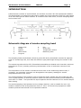
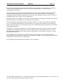
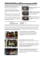
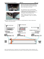
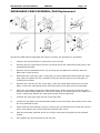
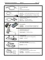
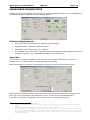
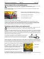
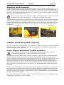
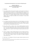
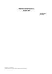
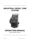
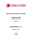
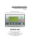
DX260/DX270 series SMOKEMETER SERVICE MANUAL TES1537E June 2009 Smokemeter Service Manual TES1537 Page 2 Smokemeter Service Manual TES1537 CONTENTS Page 3 Page No. HEALTH AND SAFETY 4 INTRODUCTION 5 OPERATION 7 Cabled Smokehead (DX260-1/DX270-1) 7 Wireless Smokehead (DX260-1BT) 7 SMOKEHEAD MAINTENANCE 9 Cleaning sample probes 10 Cleaning the lenses 10 Replacing charging contacts (DX260-1BT only) 11 Replacing the cable (DX260-1/DX270-1 only) 13 Replacing the fan assembly 13 Replacing the battery (DX260-1BT only) 14 OPTIONAL EQUIPMENT & CONSUMABLES 15 EQUIPMENT CONFIGURATION 17 Configuring or checking a Cabled Device 17 Configuring or checking a Wireless Device 17 SMOKEHEAD DIAGNOSTICS 18 DX260-1IFP INTERFACE POWER BASE (for Cabled Smokeheads) 26 Power Supply failure and replacement DX260-1CHP CHARGER BASE (for Wireless Smokeheads) 26 27 Testing the DX260-1CHP 27 Adjusting the DX260-1CHP output voltage 27 Power supply failure and replacement 28 Replacing the charging contacts 28 Adjusting the Microswitch 29 CABINET MOUNTED POWER SUPPLIES 29 Power supply replacement (cabled systems) 29 Power supply replacement (wireless systems) 30 Replacing the charging contacts 31 VERIFYING THE RS232 COMMUNICATIONS (cabled systems) 31 APPENDIX 1 – TECHNICAL SPECIFICATIONS 32 APPENDIX 2 – SPARES INFORMATION 34 AFTER SALES AND SUPPORT 46 Smokemeter Service Manual TES1537 Page 4 HEALTH AND SAFETY 1. The equipment is not weatherproof and should not be used outside in rain or snow. 2. The internal circuits and components of the analyser should not be tampered with. No internal parts are operator serviceable. 3. Operators should exercise due caution with regard to the engine fan and associated belts. 4. Always provide ventilation by using an exhaust gas extraction system or by having an adequate supply of fresh air. 5. Before starting an engine, ensure that the gear selector is in neutral or park. 6. Care should be taken with regard to scalding from the cooling system, burns from the exhaust system and electric shocks from the ignition HT system. 7. When disconnecting the fuel system of a hot engine beware of the fire hazard caused by fuel spilling onto manifolds, ignition distributor, etc. 8. Position the mains cable and sample probe in such a manner that they do not present a hazard to anyone. 9. The earth lead of the mains supply cable MUST ALWAYS be connected to a good earth point. 10. Operators should not allow themselves to come into contact with water or other similar conductors when using the equipment. 11. Equipment should only be serviced by authorised personnel. 12. All equipment should be sited in an area that is designated and clearly marked with the following: „FOR USE BY AUTHORISED PERSONNEL ONLY‟ EXTREME CARE SHOULD BE TAKEN WHERE THIS SYMBOL IS SHOWN Smokemeter Service Manual TES1537 Page 5 INTRODUCTION A Smokemeter consists of a smokehead, an interface unit and a PC with operational software. The Smokehead is a partial flow opacimeter suitable for Free Acceleration and Full Load testing of all sizes and types of diesel vehicles. It consists of two main items, a smoke sampling head and a control unit. Schematic diagram of smoke sampling head 1 2 3 4 5 Smoke inlet Heater Bypass Photo diode Purge air 6 7 8 9 Fan Green LED Temperature sensor Measuring tube The sampling head (Smokehead) utilizes a green LED and a photodiode mounted at opposite ends of a measuring tube, such that the effective light path length through the smoke is 250 mm. The measuring tube and the LED / Photodiode assemblies are heated such that their minimum temperature is 70ºC, thereby preventing condensation of the oil and water content of the smoke. The temperature of the smoke is measured at the inlet to the measuring tube so that, if necessary, an automatic correction can be applied to the opacity readings for smoke temperatures other than 100ºC. The smoke sampling head contains a fan to draw the smoke sample into the measuring tube via a by-pass system, so that the pressure inside the tube cannot normally exceed ambient by more than 7.5 mbar. This provides for rapid response and fast clearance of the smoke sample after testing. The smoke sampling head operates at low voltage (24V DC), and is suitable for use in all weather conditions and at temperatures down to -15ºC. The monitoring equipment is NOT weather protected and should not be operated outdoors. Smokemeter Service Manual TES1537 Page 6 The lenses are protected by an air curtain which reduces sooting. In addition, the sampling head has an autorange feature which can provide a step change in LED intensity to compensate for dirtiness. The measuring tube contains rings to eliminate reflection, and the LED is pulsed so that the detection system can ignore any ambient light level. Mid-point calibration is provided by automatically interrupting this pulse train to provide (for example) 3 pulses out of 8 to give a calibrated light level of 3/8 or 37.5% (patented). Sampling probes are available to suit most exhaust systems including mid-chassis and vertical. Extension poles are available for very high vertical exhausts. The smokehead communicates with a control PC either via a single 10m cable and Interface unit or via wireless (Bluetooth®) communications. The cable carries power to the head and data in both directions, for the wireless system the smokehead derives its power from internal rechargeable batteries. Depending on national requirements, various tamperproof security systems may be included. In addition, the sampling head has its serial number stored in permanent memory and the sampling head contains a clock that provides information for the printout and also to control the calibration interval. This equipment will operate from a mains supply of 100-240Va.c. single phase 50/60 Hz. If the equipment is required to operate from a different supply to this it is essential that special equipment is ordered for your requirement. The equipment should be stored and kept in a dry condition. The Bluetooth® wordmark is a registered trademark owned by Bluetooth SIG, Inc. and any use of such marks within this manual is under license. Smokemeter Service Manual TES1537 Page 7 OPERATION Cabled Smokehead (DX260-1/DX270-1) Connect the smokehead cable to the Interface base unit. Ensure the Interface base unit has power and data cables connected. Switch on power to the Interface base unit. The „Power On‟ light will illuminate and the Smokehead fan will briefly operate. There is a warm-up time of 5 to 20 minutes dependent on the outside temperature. During this time the Smokemeter will not return data to the PC. NOTE: For details of software controlled procedures, refer to the appropriate software manual. Wireless Smokehead (DX260-1BT) For wireless systems the operation of the equipment is identical but a wireless enabled Smokehead (DX260-1BT) using Bluetooth® wireless technology is utilised. When the equipment is first switched on the smokehead should be firmly positioned onto its charging base and the unit should be allowed to charge for a minimum of five to six hours (or preferably left overnight) to fully charge the batteries. The equipment screen will prompt the user to return the smokehead to its charging base between tests. This must be obeyed in order to proceed further. Failure to return the smokehead will result in depletion of the battery charge and may result in a shortened lifespan. The test will not continue until the smokehead has been returned. Blue flashing LED indicates battery charging operation Ensure the Smokehead is firmly positioned onto the charger base It is strongly advised that the Charger Cradle be left permanently switched ON with the Smokehead in situ overnight to ensure full operational usage at beginning of the working day. Please note that rechargeable batteries have a finite lifespan, therefore the battery pack will need to be replaced periodically if the smokehead is no longer sustaining sufficient charge for correct operation. Please contact a Service Engineer through Product Support. Smokemeter Service Manual TES1537 Page 8 The DX260-1BT wireless Smokehead contains a Multi-Cell Rechargeable Battery designed to give a maximum of 1.5 hours endurance from a full charge. To recharge, the Smokehead must be correctly located on its charging cradle. The Smokehead must always be replaced on the charging cradle in between tests. This will maximise the battery endurance and is also necessary for test results to be printed. On the handle of the Smokehead is a highly visible Blue Light emitting Diode (LED). This LED gives indication of the status of the Smokehead whether or not it is on its charging Cradle. Battery Charging Modes and Endurance: The nominal endurance of the internal Battery pack is 1.5 hours continuous use from a full charge and cold start. This will vary according to ambient temperature. For optimum use and battery life, the smokehead should be removed from the charging cradle for the minimum amount of time and returned to the charger immediately after testing as prompted by the smoke test Software. The rate of charging is dependant on a combination of Battery Voltage and Battery Temperature. If the Smokehead has seen reasonable use the charger will switch to „Fast Charge‟, taking approximately 1.5 hours to fully recharge. Once full terminal Voltage has been reached, the battery charging rate is reduced to „Trickle Charge‟. When charging for a protracted period, for example overnight, a trickle charge of 15 hours will completely recharge the internal battery. A blue LED on the Handle indicates the Charging Status. The Blue LED on the Handle of the wireless Smokehead determines the Charging Status. With the wireless Smokehead‟s charging unit plugged in to a Mains Supply and switched on: With the Smokehead returned to Charging Cradle: LED flashing slowly (ON for 1 second, OFF for 1 second): The Smokehead battery is in „Slow Charge‟ mode, the charging rate determined by either Terminal Voltage or, Battery Cell temperature. LED flashing rapidly (2.5 times per second): This shows the Smokehead is in „Fast Charge‟ Mode. The battery should be fully charged within 1.5 hours. LED flashing very rapidly (5 times per second): This indicates that the Smokehead has just been returned to its Charging Cradle and has detected that it is „On Charge‟ . This Status lasts for only a few seconds. LED fast Flicker (8 flashes/sec) on returning Smokehead to Charger: Poor contact with charger. Remove Smokehead from charger and replace. If problem persists remove Smokehead, clean all contacts (Smokehead and charger) and ensure the charger pins spring back after compression. If the problem still exists, contact your Helpline. With the Smokehead removed from Charging Cradle: LED ‘ON’ continuously: Smokehead is running on internal Battery. LED pulsing ‘ON’ for 2 seconds, ‘OFF’ for 0.5 seconds: Smokehead battery has reached a Low Voltage condition, and has less than 10 minutes life left before Auto-shutdown. LED ‘OFF’: After above Low Voltage condition: Auto Shut down due to Low Voltage. No more testing possible, return Smokehead to Charging Cradle for recharging. If the Smokehead has received no Communication from Host Computer for over 6 minutes and has gone into „Sleep‟ Mode. -- Return the Smokehead to the Charging Unit to invoke a response. Smokemeter Service Manual TES1537 Page 9 Fault Diagnosis: Check the Charging Cradle is connected to the 240 V AC Mains. If there are problems encountered with the charging process the following should be observed: No LED Lit on Smokehead: Return the Smokehead to Charging Cradle. LED should display according to Charging level required. No LED lit on Smokehead after returning Smokehead to Charging Cradle: Check that the Smokehead is correctly seated on the charging Cradle. The Smokehead has twin connectors on each insulated foot, and may be connected either way round. Check that the connectors that transmit the Charging Current on the Charging Cradle are clean and not stuck in a depressed condition. Check that the Charging Connectors on the insulated mounts on underside of the Smokehead are clean and free of dirt and obstructions. To check the charging Voltage at the Charging Cradle: Connect a Digital Multimeter across the two charging Connectors on the charging Cradle, and depress the Central micro switch. A Voltage of 30 Vdc +/- 0.5v should register on the Multimeter Display. The internal battery pack has a finite lifespan and will need to be replaced periodically. SMOKEHEAD MAINTENANCE The following operations are possible for Field Service on the cabled (DX260-1) and wireless DX260-1BT) Smokeheads. DX260-1 Function Check Lens and sample probe cleaning Power/data cable change/Repair and Plug Change/Repair Fan and Grill/Filter replacement. DX260 Interface Box Check DX260-1BT Function Check Lens and sample probe cleaning Fan and Grill/Filter replacement. Battery Pack Check and Replacement Smokehead Charging Contact check/Replacement Smokehead Charger Voltage check and Contact Replacement. Any other operations involving the DX260 Smokemeter are outside the scope of this Service Manual and the Smokemeter should be returned to Customer Service for examination. It is recommended that any Smokemeters that are to be bench examined, or repaired are thoroughly cleaned with a proprietary degreaser to remove all external traces of diesel residue as well as garage grime and oil. Smokemeter Service Manual TES1537 Page 10 Serial numbers Serial number locations are as follows: Smokehead internal - Underneath the lens housing (remove end cap for access). Smokehead external – on underside of Smokehead. CLEANING SAMPLING PROBES Under normal circumstances the sampling head does not require cleaning . If a sampling probe becomes restricted with deposits, test results can be affected. To clean a sampling probe, remove the sample probe from the smokehead. Blow through the sample probe only, using compressed air. DO NOT BLOW THROUGH THE SMOKEHEAD. CLEANING THE LENSES Two lenses are fitted in the smokehead, one at either end. The Smokemeter checks the cleanliness of the lenses at the start of each test, and the PC will provide a warning when cleaning is required. ACCESSING A LENS The cleaning procedure is as follows. 1. If fitted, remove the sampling probe. 2. Unscrew the knurled knob at the sampling probe end of the sampling head and remove the end cap. 3. Carefully pull out the lens housing and wipe the lens with a soft cloth (if required, a little methylated spirit will assist cleaning). 4. Refit the lens housing with the arrow pointing upwards (a little silicon grease on the 'O' ring will assist fitment – but do not get on the lens!). 5. Refit the end cap and tighten the knurled knob. NOTE: Ensure the end cap locates fully against the body of the sampling head before tightening the knob. If not correctly located, the lens housing is probably not fully home. 6. Clean the lens at the other end of the smokehead in the same way. NOTE: The end cap for the sampling probe must be fitted at the end away from the sampling head cable. Smokemeter Service Manual TES1537 Page 11 Charging Contact check/Replacement (DX260-1BT only) Firstly it is important to identify the condition of the contacts and ascertain the likely cause of the contact failure. To replace the Smokehead contacts carefully follow the procedure below taking care not to lose any washers or spacers used. Remove both of the end cap plates from the Smokehead by unscrewing the knurled securing screws. Put end cap plates aside. Using a cross-head Screwdriver remove the 4 screws from the plain end cap plate, and remove the plate. Put the plate and screws aside for reuse. GOOD The contact has slight wear, but otherwise acceptable. POOR The contact is slightly corroded through contact with dirt etc. Also small signs of pitting of the plating. BAD The contact shown left is showing bad signs of arcing and corrosion and should be replaced. A Service Kit DAS00560 for contact replacement comprises the following components: M12 Washer WSHR1086 x1 Contact block assembly DAS00553 x1 Smokehead contacts DDL00293 x4 The DDL00293 Smokehead contacts are used for the foot contact replacement. The remaining components are used on the charger base (which should ideally be replaced at the same time). Remove the other end cap plate with the fan by similarly unscrewing the 4 cross-head screws. Carefully remove the fan and end cap, and after noting the way the cables are connected inside the Smokehead, carefully disconnect the red and black fan drive wires by gently pulling downwards on the white Molex connector. At the Exhaust end of the Smokehead: Pull the 2-way Fan Cable connector, the 4-way Power/Comms Connector and the battery pack connector downwards to disconnect from the main PCB. At the Inlet end of the Smokehead: Pull the Temperature Sensor connector downwards to disconnect. Use M7 Spanner to release M4x20 Hex bolt. Use Fine nosed pliers to prevent charging contact from rotating with the bolt. Remove bolt, washers and carefully withdraw disconnected battery pack. Put battery pack safely aside. This centre screw and bolt retaining the battery DIN rail must be removed to permit access to the negative or ground terminal. Use a 7mm spanner where necessary to undo the contact retaining bolts and the Din rail nut. Smokemeter Service Manual TES1537 Page 12 Use fine nosed pliers carefully to grip the flats on the Contacts so that the Hex head bolts retaining the contacts can be undone with a 7mm spanner as shown. The reassembly of the new Smokehead contacts into the rubber feet is the reverse of dismantling. Care must be taken to include the small cylindrical metal spacer in the Negative terminal Rubber Feet. Ideally, lightly lubricate the four charger contacts with WD40 or light oil to prevent corrosion. DDL00293 Charging contacts are used for the Smokehead foot contact replacement – quantity 4 per Smokehead After dis-assembly and re-assembly of the smokehead charging contact assembly a full continuity check should be carried out to ensure connectivity and short-circuit prevention. Smokemeter Service Manual TES1537 Page 13 SMOKEHEAD CABLE RENEWAL/FAN Replacement Should the cable become damaged and require renewal, the procedure is as follows. 1. Unscrew the knurled knob (1) and remove the end cap. 2. Remove the four countersunk screws (2) which secure the internal fan and grille to the smokehead end plate. 3. Remove the four panhead screws (3) securing the end plate and carefully ease the plate clear of the housing. 4. Disconnect the 4-pin plug (4a). If carrying out a fan replacement disconnect the 2-pin plug (4b) and replace the fan. Carefully fit the fan and fan grille to the end plate (4 countersunk screws). 5. Remove the 4 wires from the 4-way plug. Undo the metal cable clamp from the end plate. Loosen the cable gland strain relief and remove the cable from the end plate. 6. Re-fit the new cable through the cable gland strain relief and secure to the end plate with the metal clamp (Important: secure the clamp on the earth braid of the cable). Refit the 4-way plug. Ensure the cable gland strain relief is tightened. 7. Connect the 4-pin plug (4a) and the 2-pin plug (4b). 8. Locate the end plate to the smokehead (cable on left hand side) and loosely secure with the four panhead screws. 9. Check that the lens housing is fully in, then fit the end cap and secure with the knurled knob. Fully tighten the knurled knob then slacken half a turn. 10. Push the end plate upwards as far as it will go, and then fully tighten the 4 panhead screws. 11. Fully tighten the knurled knob on the end cap. Smokemeter Service Manual TES1537 SMOKEHEAD BATTERY REPLACEMENT Page 14 (DX260-1BT only) Should the battery pack require renewal, the procedure is as follows. 1. Unscrew the knurled knob (1) and open up both end caps. 2. Remove the four panhead screws (2) & (3) securing the end plates and carefully ease the plates clear of the housing. 3. At the fan end, disconnect the 2-pin plug (4a) and also the 2-pin plug (4b) connected to the fan. 4. At the probe end, disconnect the 3-pin plug (5). 5. Depending on which version - loosen the two screws (6a) or the plastic spacer (6b) securing the battery pack and remove old battery pack, do not remove by pulling the cables. Ensure the connectors do not foul any components during removal/replacement of the board. 6. Replace with new battery pack (note orientation). Discard the two securing screws (earlier versions) or the plastic spacer (later versions) – no longer required. 7. Re-connect the 2-pin plug (4a), the 2-pin plug (4b) and the 3-pin plug (5). 8. Relocate the end plates to the smokehead and loosely secure with 4 panhead screws (7). 9. Check that the lens housing is fully in, then fit the end caps and secure with the knurled knob. Fully tighten the knurled knob then slacken half a turn (8). 10. Push the end plate upwards as far as it will go, and then fully tighten the 4 panhead screws. 11. Fully tighten the knurled knob on the end caps. NOTE: Ensure the battery is disposed of in accordance with current rules and regulations applicable and enforced in your area. When the equipment is first switched on the Smokehead should be firmly positioned onto its charging base and the unit should be allowed to charge for a minimum of five to six hours (or preferably left overnight) to fully charge the batteries. Smokemeter Service Manual TES1537 Page 15 OPTIONAL EQUIPMENT & CONSUMABLES DX210-4A Sampling probe (Standard) DX210-4A-L Sampling probe (Large) For large aperture exhausts (>70mm) DX210-6 Sampling pipe (Standard) For vertical stack exhausts DX210-6L Sampling pipe (Standard) For large vertical stack exhausts (>70mm) Cable – Smokehead Cable Assembly DAS00497 DAS00559 10m Standard 0.6m (Use with AS09188 Interface Module) Cable – Interface to PC, Serial Null Modem 2m DX230-261 9 way D (Female to Female) Cable – Serial comms cable from PC to VOSA Smartcard reader (UK only). AS08804 (Note: May already be fitted if host PC has EGA) DX260-1BT/01 Battery Pack (For use with DX260-1BT Head only) DX230-130/16 Fan Kit (Replacement fan for DX260-1 & DX260-1BT) Tacho Comms Cable AS09133 DX230-261 5m Standard (for CDSS1) 2m Standard (for CDSS4, CDSS6) Battery Tacho Power/Sensing cable CABL3016 CDSS3/4/6 to vehicle battery Battery Tacho Power/Sensing Cable CABL3023 CDSS3/4/6 to vehicle accessory socket Smokemeter Service Manual TES1537 Page 16 Inductive RPM Clamp HTP3 For use with CDSS3/CDSS5 Oil Temperature Probes TRDU0127 Use with CDSS4/CDSS4BT only (5m cable) DX210-25A DX210-26 2.5m (Use with DX211-11 or DX211-11BT) 0.75m (Use with DX211-11 or DX211-11BT) Temperature Probe Adapters (use with DX210-25A and DX210-26 probes) DX211-11 – 5m cabled Adapter DX211-11BT – Wireless Probe Adapter Power Supplies PWRS0031 PWRS0035 – 30v (use with wireless smokehead only) – 24v (use with cabled smokehead only) Smokehead Diagnostic Kit (Use with all Smokeheads) DX260-DIAGKIT – Software included Contact Block Kit (use DX260-1CHP Smokehead Charging Base) AS09662 Pre-wired Contact Block Assembly (use on Cabinet mounted Smokehead charger) DAS00553 Pre-wired Contact Replacement Kit (use on Smokehead feet & Smokehead charger) DAS00560 DDL002963 Pre-wired kit Smokehead foot contacts (Sold individually) Smokemeter Service Manual TES1537 Page 17 EQUIPMENT CONFIGURATION From the Platform Configurator screen of the host PC you can configure all peripheral devices either as „Wired‟ or „Wireless‟. To configure/re-configure or verify all peripheral equipment to the host computer the following configuration procedure should be followed: Configuring or Checking cabled device settings Minimize the main program and from the „Start‟ menu select the following: Start/Programs/Dieseltune (or Crypton)/Platform Configuration/Platform Configuration Utility For each wired device selected ensure that the „Wired‟ button is checked and the correct port identification entered in the „Port‟ entry box. Select „Save‟ then „Exit. Configuring or Checking wireless device Settings The Bluetooth® devices communicate to a controlling Personal Computer using Bluetooth® wireless technology. The configuration of the Bluetooth® wireless link will need to be verified and changed if a replacement device is fitted to an existing Smokemeter system. To verify the Bluetooth settings of the Smokehead, and if supplied, Temperature Probe, Test Progression Handset or the wireless Battery Tachometer/EOBD unit, or maybe to change the settings if replacement devices are fitted, the following configuration procedure should be followed: The Bluetooth ID (BTID) will need to be entered in the program. The Bluetooth® devices communicate to a controlling Personal Computer using Bluetooth® wireless technology. The configuration of the Bluetooth® wireless link will need to be verified and changed if a replacement device is fitted to an existing Smokemeter system. Minimize the main program and from the „Start‟ menu select the following: Start/Programs/Dieseltune (or Crypton)/Platform Configuration/Platform Configuration Utility Select the device to be configured. Ensure „Wireless‟ is checked. Enter the Bluetooth ID for the device in the „Bluetooth Address‟ box. This address is a 16character string identified on the device serial label. Select „Save‟ and „Exit‟. Smokemeter Service Manual TES1537 Page 18 SMOKEHEAD DIAGNOSTICS Testing of the Crypton/Dieseltune DX series of Digital Smokehead is done using the PSA80533 Smokehead monitor program a DX.260 Diagkit test kit. Software Requirements PC with at least one serial port or USB-Serial port adapter. 32 Bit Microsoft® Windows operating system1 Microsoft® .NET® Framework 1.1 or higher2 For wireless units, a Bluetooth® Software Stack that supports Virtual COM ports with no compulsory pairing (e.g. WIDCOMM, Toshiba but not Microsoft®)3 Operation The software (a single executable) does not have to be installed and can be run from a memory stick or network share (with appropriate permissions) When the program is started, it will present a dialog box similar to that shown below. Ensure the smokehead is powered and connected, then select the COM port 4 using the dropdown list. The test software will immediately try to connect to the smokehead and, if successful, will display information and readings similar to those shown below . 1. 2. 3. 4. All trademarks are acknowledged .NET v2.0 redistributable installation package (dotnetfx.exe) is included on the PSA80533 medium This issue will be addressed in later versions of the software. For wireless units, you must first connect the smokehead to a virtual COM port. Consult your Bluetooth module documentation for instructions. The Smokehead Bluetooth address by which it may be identified is printed on the serial number label. Note that pairing is not supported by the smokehead. Smokemeter Service Manual TES1537 Page 19 Basic smokehead information The basic smokehead information appears in the Smokehead group. For example, with a Dieseltune UK smokehead: The name is shown as DX260-1 The PIC Firmware is shown as 1.11 The MCU Firmware is shown as A2 The serial number should match the label The Time will be updating. Set the time, if necessary, by clicking in the box. The time will then stop updating and the new time may be entered. Press the Set button to update the smokehead real time clock. If the Time box has been clicked in accidentally, clear the box & press set. The updating current time will then re-appear. The date cannot be altered using this program. Note that it is in UK format i.e. dd/mm/yyyy If the smokehead RTC chip has suffered a power loss, the phrase “Time and Date Invalid” will appear below the date. This will disappear when the time is set. Smokemeter Service Manual TES1537 Page 20 Charger5 The Charger group shows the current state of the battery pack charging system. Mode The charger has six modes of operation. These are: Off – Smokehead is not on charging cradle or charger power is off On – Smokehead is on the charging cradle and is determining the optimum charging mode Fast – Smokehead is fast charging the battery pack. The Fast Charge mode will finish within 90 minutes as indicated by the 'Ends in' value displayed or earlier if the Battery Pack terminal voltage exceeds 28.5V or if the Battery pack temperature rise is excessive. Slow – Smokehead is charging the battery pack at the 15 hour rate. The time at which it is due to finish is as indicated in the 'Ends at' value displayed. It will, however, terminate earlier if the Battery Pack terminal voltage exceeds 28.5V Top-Up – The Fast charge does not fully charge the battery pack so a subsequent period of up to 4 hours at the 15 hour rate is used to top-up the charge. The time at which it is due to finish is as indicated in the 'Ends at' value displayed. It will, however, terminate earlier if the Battery Pack terminal voltage exceeds 28.5V Trickle – Smokehead is charging at a very low rate to maintain the Battery Pack in its fully charged state. The mode follows the termination of Top-Up or Slow charging modes Drive The Drive bar gives an indication of the charging current control setting required to achieve the optimum current for the mode. As the Battery Pack terminal voltage increases, the control is set higher to maintain the current at a constant level. When the charging mode changes, the drive is adjusted to set the new current. Contacts In the event that the charging contacts become pitted, corroded or loose, the presence of the charger may be detected but little or no charging current flow in spite of maximum drive setting. This condition causes the Contacts display to change from 'GOOD' to 'POOR'. Since all smokehead boards are 'wireless ready', this may also be displayed on wired smokeheads. 5. The Charger group applies only to battery operated, wireless smokeheads and has no significance with wired smokeheads. Smokemeter Service Manual TES1537 Page 21 Battery Pack6 The Battery Pack group gives information on the state of the rechargeable battery pack within the previous 60 seconds. Due to the continuous smokehead heater switching, the values are heavily filtered thus the effect of charging mode changes will take a while to be visible. Terminal Voltage The battery pack terminal voltage gives an indication of the state of charge of the Battery Pack Voltage Variation This shows the difference in terminal voltage caused by the switching of the heater current or a change of charging mode. Its purpose is to estimate the internal resistance of the battery pack which increases with time and charge cycling. When the pack has been fully charged and the Smokehead at operating temperature, remove the smokehead from the charging cradle. Let the smokehead stand for 30 seconds, then turn on the fan (see below) and press the “Reset Battery Data” button. A Voltage Variation reading of more that 2 Volts within 30 seconds indicates a suspect battery pack. Terminal Voltage Change Rate This give an indication of the Battery Pack internal resistance to charging but is less reliable that the voltage variation. Charging Current This shows median value of up to 60 readings of the charging current and provides a means of checking that the charger is operating correctly. Temperature This reading shows the temperature of the cells in the battery pack. The cell temperature is important for determining the optimum charging mode. The range of the reading is from 1°C to 60°C (approx) Temperature Change Rate This reading shows the heating effect of the current during charging and discharging. A rate of temperature rise of more than 1°C per minute for 3 consecutive minutes is used to terminate Fast charging mode early. 6. The Battery Pack Group and the “Reset Battery Data” button at the bottom of the dialog box, apply only to battery operated, wireless smokeheads and have no significance with wired smokeheads. Smokemeter Service Manual TES1537 Page 22 Gas Diode and Heaters For smokehead calibration purposes, the heaters must be operating at the normal measurement levels. This is especially important when selecting the Photodiode amplifier gain 'Select On Test' (S.O.T) resistor. When the heaters are running at the correct level, the background colour will be Green The forward voltage drop of the Gas Diode has been accurately measured at 50°C and is written on the measurement tube assembly outer plastic tube. The Gas Temperature calibration is set by the 10-turn potentiometer (R65) using a calibrated voltmeter accurate to 1mV and the supplied DX.260 DIAGKIT Calibration Box. DX.260 DIAGKIT To calibrate the Gas Temperature Sensor Diode: 1. Unplug the 2-way lead coming from tube assembly from the 9-way heater connector and connect the 2-way lead from calibration box. 2. Adjust the 10 turn resistor on the test box for the meter reading written on the tube assembly (e.g. .677 = 677mV). 3. Adjust the 10 turn potentiometer on the smokehead board (R65) for 50°C Gas reading (Green background colour). Ensure meter reading has not changed; adjust and repeat as required. 4. Unplug the calibration box & reconnect the Gas Diode lead from the tube assembly. Smokemeter Service Manual TES1537 Page 23 Optical Measurement System The Optical Measurement System group shows a number of parameters. To assist with setting up & calibration, background colour has been used to highlight in-spec and out-of-spec conditions on relevant readings. Live Reading Percent Obscuration This is the raw, unfiltered reading from the optical system. When selecting the Photodiode amplifier S.O.T. Resistor, the background will be Green for optimal resistor values. This is the raw, unfiltered obscuration calculated from the Live readings and the Min & Max values. It is for use with Neutral Density Filters of known transmission factors to check the system linearity. Set Zero Resets the Min. Max. and the Cal. Point values. Set Range Resets the LED Drive. The Live reading may drift for a time after range setting so the Set Zero button is disabled for 10 seconds. LED Drive range This is the LED brightness which is set to compensate for soot build-up on the lenses. For new unit calibration purposes, it must be 0. Auto-calibration check This is the result of the patented self calibration calculation. It should be 62.5% ± 3%. Correct values are shown on a Green background. Optical Reading Range The Min. and Max readings are the basis of the calibration and Percent Obscuration calculations Min. should be <61, Max. = 770 to 975 Correct values are shown on a Green background. If the Photodiode and/or LED cell has been replaced, it may be necessary to change the S.O.T resistor (R7). This is facilitated using a DX.260DIAGKIT Calibration Box To select the optimum resistor: 1. Ensure the heater readings are normal and stable. 2. Remove the existing S.O.T resistor. 3. Set the LED Drive range using the 'Set Range' button. Ensure the Range is Zero (Green background). 4. Connect the crocodile clips from the DX.260 DIAGKIT Calibration Box across the resistor fitment posts and dial-up successive resistor values using the rotary switches until the Live Reading background goes Green 5. Fit a fixed resistor of the value indicated by the DX.260 DIAGKIT Calibration Box Label. Smokemeter Service Manual TES1537 Page 24 Fan Operation The fan can be operated and the current checked. Acceptable current levels (whether On or Off) are shown on a Green background, incorrect values on a Pink background. Note that the start-up current may be high enough to cause a brief Pink background; this is acceptable. Adaptive Acoustic Progression The Acoustic Progression system can be exercised. When the smokehead first connects, the Current Threshold reading has the default background. Clicking the “Set Trigger” button causes the Automatic Setting procedure to start. If no trigger is obtained, the background colour will turn Blue and the smokehead will set the Threshold to 72. If the system could not clear a trigger (e.g. too much noise, incorrect microphone wiring or circuit failure), the background colour will turn Pink and the smokehead will set the Threshold to 72. All other conditions will show the threshold set by the system on a Green background Smokehead Status The Smokehead Status area shows the live state of the Smokehead as returned by the “Get Status” command. The Messages shown below represent (from left to right) bits 0 to 6 of the Status Byte. Under normal operation, “On Charge” (always on a wired unit) and, occasionally, “Battery Low” (even on a wired unit) will be seen. “Progress Test” will show for a period when the Acoustic Progression Trigger Threshold is exceeded. “Time Suspect” and “Date Suspect” may be seen if the Real Time Clock has lost power (see Basic Information) or if the Time and/or Date have been corrupted. They may be cleared by setting the time and date then power cycling the Smokehead. “MCU Not Responding” and “I2C Not Responding” indicate hardware problems and should never be seen. Program Status A program status area exists between the Smokehead Status and the bottom row of buttons. Messages that may be seen there include “Connecting to smokehead”, “Connecting - Please wait....” and “The smokehead is not responding”. With the latter, check that the correct COM port number was selected and the Smokehead is both connected to it and powered. If the wrong port was selected, exit the software and restart it. Smokemeter Service Manual TES1537 Page 25 Buttons The “Change Smokehead” button should be used when you wish to disconnect one smokehead and test another (on the same COM port). Clicking it sends a “Power Down” command to the Smokehead (turning off the Optical Measurement System & heaters), closes the COM port and clears all the data from dialog box. The button legend then changes as shown. 7 The “Reset Battery Data” clears the accumulated data used to generate the Battery Pack group display (see Battery section above). It is of no relevance to wired smokeheads. The “Exit” Button sends a “Fan Off” command, closes the COM port and exits the program. It does NOT send the “Power Down” command 7. For wireless units, you must first connect the desired smokehead to the previously allocated virtual COM port before pressing the 'Connect Smokehead' button. Note that pairing is not supported by the smokehead. Smokemeter Service Manual TES1537 Page 26 DX260-1IFP INTERFACE BASE (cabled Smokehead) The interface power base supplies power for the cabled smokehead. The power supply is nonadjustable and has a fixed output of 24v. (On earlier models the power supply is adjustable with its output set at 24V +/-0.2V DC. For adjustment of replacement of this power supply follow instructions as for DX260-1CHP). The DX260-1IFP Interface Base also relays wired communication from the DX260-1 cabled smokehead to the controlling PC through an RS232C connection. The Power Supply providing the 24V can be easily checked for the correct output voltage at the smokehead end, where PL2 4Way connector, Red to Black should provide a minimum 24.0V DC. There will be a voltage drop along the cable which is normally 10m in length. Maximum current demand from the power supply will be approximately 2.3A at 24V DC. Maximum current demand is usually on start up from cold as the tube and optic heaters pull maximum current to achieve an over-temperature condition prior to cooling to their specified temperatures. To check the Output Voltage of the DX260-1IFP: Unplug the DX260-1 smokemeter, and power up the interface power base unit: Using a Digital Multimeter (DMM) set to measure 30V DC , with the Negative probe connected to Pin 2 (black) and the Positive Probe to Pin 6 (red): The measured Voltage with the unit powered up should be 24V DC. 6 2 Picture left shows external view of DX260-1 Smokehead Socket. Power Supply failure and replacement: Before carrying out any work within the DX260-1IFP Interface Base - firstly ensure that all external connections are removed – in particular the Mains Power Input. Remove the 8 cross-head screws securing the lid to the base, remove the lid section from the base, and turn it over so that the power supply and associated wiring is revealed. Remove using a cross-head screwdriver the 8 screws securing the smokehead holder to the Base: 2 screws at each end (as shown) 2 screws at each side (1 shown) Illuminated ON/OFF SWITCH Disconnect the mains power connector from the power supply, then unplug the 2.1mm power connector from the secured socket. The power supply can now be carefully removed from the base by pulling up and away from its securing pad. Re-fit with the replacement power supply unit and re-make its connections. Refit the smokehead cradle top to the base with the 8 cross-head screws. Finally, reconnect mains power lead and enable power to the DX260-1IFP Interface Power Base. Test for correct output Voltage at the Smokehead socket as previously described. If the correct Voltage is present, reconnect the Smokehead. Check that the external metalwork is earthed. Smokemeter Service Manual TES1537 DX260-1CHP CHARGER BASE Page 27 (wireless Smokehead) Testing the DX260-1CHP The unit can be tested by measuring the output voltage at the charger pins whilst pressing the centrally mounted micro switch down. A Digital Multimeter (DMM) set to measure 30V DC should be used and the probes connected as shown: Multimeter NEGATIVE Probe Microswitch Multimeter POSITIVE Probe The Voltage across the Pins should be 30.0 V +/- 0.5V dc If the Voltage is within the above range, then no adjustment of the internal power supply Voltage is necessary. Adjusting the DX260-1CHP Charger Output Voltage Before carrying out any work within the DX260-1CHP Charger Base - firstly ensure that all external connections are removed – in particular the Mains Power Input. Remove using a cross-head screwdriver the 8 screws securing the smokehead holder to the Base: 2 screws at each end (as shown) 2 screws at each side (1 shown) Illuminated ON/OFF SWITCH An insulated trimming tool is required to adjust the internal power supply output voltage potentiometer. A Digital Multimeter set to read 30V DC should be connected across the + Red and – Black output voltage terminals of the power supply. Check that the spring-loaded connectors are clean and not stuck in a depressed condition. Also check that the crimp connections to the switch and mains IEC connector are secure. The mains 240V should be connected and the charger switched on at the red On/Off switch shown previously. The voltage displayed on the Digital Multimeter should be 30.0V +/- 0.5V DC. Adjust the potentiometer carefully clockwise to increase the Voltage, and anti-clockwise to reduce. Switch off power at the switch and remove the power input cable. Reassemble the charger Unit, refitting the charger cradle to the base, and replacing the 8 cross-head screws. Reconnect the charger unit to the local mains power, switch the charger ON, and retest the output charging voltage by connecting the DMM across the Positive and Negative charging Pins, and depressing the central micro switch. Check that the DMM displays 30.0V +/-0.5V DC Check that the charging connectors on the underside of the Smokehead feet are clean and free of dirt and obstructions. Check that the external metalwork is earthed. Smokemeter Service Manual TES1537 Page 28 Power Supply failure and replacement: all Before carrying out any work within the DX260-1CHP Charger Base - firstly ensure that external connections are removed – in particular the Mains Power Input. Remove Charging Base cover as described in previous section: „Adjusting the DX260-1CHP Charger output voltage‟. Remove using a cross-head screwdriver the 8 screws securing the smokehead holder to the Base: 2 screws at each end (as shown) 2 screws at each side (1 shown) Illuminated ON/OFF SWITCH If faulty the power supply is non-repairable and should be replaced: Remove the cables from the power supply noting their positioning. Remove the securing screws on the underside of the power supply and remove the unit. Replace the power supply and affix using securing screws. Re-affix the wires to their correct locations. Reassemble the Mains Chassis Assembly to the cabinet and re-affix the smokehead bracket. Charging contacts failure and replacement: Before carrying out any work within the DX260-1CHP Charger Base - firstly ensure that all external connections are removed – in particular the Mains Power Input. Charger base contact replacement will be required if the contacts have become severely corroded. Corrosion will occur if arcing has been taking place due to incorrect microswitch adjustment or can be a result of the contacts becoming dirty from contaminants and debris picked up from the workshop floor. Restricted movement of the contacts may also occur as a result of dirt or excessive heat from arcing. The contacts are replaced as a kit (AS09662) comprising two contact block assemblies. Access to the contact blocks can be achieved by removing the cover on the Charging Base. Remove the push-on retainers securing the contact blocks and pull out the blocks from the metal assembly. The contact block with the red lead is connected to the microswitch. Disconnect this red lead at the microswitch. The contact block with the black lead is connected to the power supply –V output. Disconnect this black lead at the power supply. Discard the old contact blocks and re-assemble the replacement contact blocks to the metalwork using the supplied push-on retainers and ensure there is free movement of the spring contacts (uninhibited by wire positioning). -V (Black lead) +V (Red lead) Re-connect the red lead to the microswitch and the black lead to the power supply –V. Re-assemble all parts and covers. Re-connect the mains power supply and check the presence of 30Vdc +/- 0.2V at the pin contacts when the microswitch is operated. Check that the external metalwork is earthed. Smokemeter Service Manual TES1537 Page 29 Adjusting the Microswitch Charger base microswitch height adjustment should be set so that the microswitch (Fig. 1) is heard to operate when the smokehead foot is between 1-2mm from the charging base (Fig. 2). If the microswitch is set to operate at a too high a setting then arcing of the charging contacts will occur. If it is set too low then it may fail to activate. Access to the microswitch is achieved by removing the Charger Base cover. Before carrying out any work within the DX260-1CHP Charger Base - firstly ensure that all external connections are removed – in particular the Mains Power Input. The microswitch height should be adjusted to the correct height by removing the microswitch retaining nut, dropping the microswitch away from the chassis and inserting an M12 washer (WSHR1086) between the microswitch and the cradle (Fig. 3). Re-fit the microswitch with its retaining nuts, re-fit the Charger Base cover and check for correct operational height using a Smokehead. Microswitch M12 Washer Fig. 1 Fig. 2 Fig. 3 CABINET MOUNTED POWER SUPPLIES On some equipment the wired DX260-1 Smokehead is powered directly from the cabinet Mains Chassis Assembly or the wireless DX260-1BT Smokehead may be charged from the cabinet mounted charging cradle assembly. Power Supply replacement (cabled systems): Before carrying out any work within the cabinet - firstly ensure that all external connections are removed – in particular the Mains Power Input. To replace the internal power supply it will be necessary to open the Mains Chassis Assembly located inside the cabinet. To remove the Mains Chassis Assembly first ensure that mains power is switched off and the power lead disconnected from the equipment. Remove the three securing screws that hold the smokehead bracket to the cabinet and discard the bracket. Remove the fourth screw next to the bracket to release the Mains Chassis Assembly from the cabinet. From inside the cabinet remove all connecting leads to the Mains Chassis Assembly then remove the unit from the rear of the cabinet. The Smokehead power supply will now be accessible. Disconnect the mains power connector from the power supply, then unplug the 2.1mm power connector from the secured socket. The power supply can now be carefully removed from the base by pulling up and away from its securing pad. Re-fit with the replacement power supply unit and re-make its connections. Reassemble the Mains Chassis Assembly to the cabinet and re-affix the smokehead bracket. For newer wired systems the power supply is not adjustable. It is also a non-repairable item and should be replaced if it becomes faulty. Smokemeter Service Manual TES1537 Page 30 Power Supply adjustment or replacement (wireless systems): Before carrying out any work within the cabinet - firstly ensure that all external connections are removed – in particular the Mains Power Input. To adjust the internal power supply voltage, it will be necessary to open the Mains Chassis Assembly located inside the cabinet. To remove the Mains Chassis Assembly first ensure that mains power is switched off and the power lead disconnected from the equipment. Remove the three securing screws that hold the smokehead charging cradle to the cabinet and remove the cradle. Remove the fourth screw next to the bracket to release the Mains Chassis Assembly from the cabinet. From inside the cabinet remove all connecting leads to the Mains Chassis Assembly then remove the unit from the rear of the cabinet. The Smokehead power supply will now be accessible: An insulated trimming tool is required to adjust the internal power supply output voltage potentiometer. A Digital Multimeter set to read 30V DC should be connected across the + Red and – Black output voltage terminals of the power supply. Check that the connectors that transmit the charging current on the charging cradle are clean and not stuck in a depressed condition. Also check that the crimp connections to the switch and mains IEC connector are secure. The mains 240V should be re-connected and the charger switched on – IMPORTANT – BE VERY CAREFUL - MAINS VOLTAGES PRESENT. The voltage displayed on the Digital Multimeter should be set to 30.0V +/- 0.5V DC. Adjust the potentiometer carefully clockwise to increase the Voltage, and anti-clockwise to reduce. Switch off power at the switch and remove the power input cable. Reassemble the Mains Chassis Assembly to the cabinet and re-affix the smokehead bracket. If faulty the power supply is non-repairable and should be replaced: Ensure that the Mains Power input is removed. Remove the cables from the power supply noting their positioning. Remove the securing screws on the underside of the power supply and remove the unit. Replace the power supply and affix using securing screws. Re-affix the wires to their correct locations. Reassemble the Mains Chassis Assembly to the cabinet and re-affix the smokehead bracket. Smokemeter Service Manual TES1537 Page 31 Replacing the Charging contacts: Before carrying out any work on the charging assembly - first ensure that all external connections are removed – in particular the Mains Power Input. Charger base contact replacement will be required if the contacts have become severely corroded. Corrosion will occur if arcing has been taking place due to incorrect microswitch adjustment or can be a result of the contacts becoming dirty from contaminants and debris picked up from the workshop floor. Restricted movement of the contacts may also occur as a result of dirt or excessive heat from arcing. The contacts are replaced as a complete contact block assembly DAS00553. Access to the contact block can be achieved by removing the cover on the cradle. Remove central fixing screw of contact block assembly. and remove the contact +V (Red lead) block. The red lead is connected to the microswitch. Disconnect this red lead at the microswitch. The black lead of the -V (Black lead) contact block is connected to the power supply –V output. Re-assemble the contact block and ensure there is free movement of the spring contacts (uninhibited by wire positioning). Re-connect the red lead to the microswitch and the black lead to the power supply –V. Re-assemble all parts and covers. Re-connect the mains power supply and check the presence of 30Vdc +/- 0.2V at the pin contacts when the microswitch is operated. Verifying RS232 Serial Communications (wired systems): The correct operation and functioning of the wired DX260-1 Smokehead is the only means of verifying correct serial communications. When a (known good) Smokehead is first plugged in and powered up, its fan will operate briefly (for about 0.5 second)s. This indicates only that the Smokehead has power and has started running its own internal firmware program. If incorrect operation of the Smokemeter system occurs, and any error message observed on the host PC screen, such as “Smokehead not Communicating”, then it is possible the Serial Communications have failed. The most likely cause of a wired Smokehead communication failure is a defective cable. Damage to the cable may be caused by full or partial severing, damage to insulation or shorting of internal wire cores. Any damage to the cable may prevent the smokemeter from starting up, and the brief start-up noise of the fan may not be heard. Attempt a software restart, and if the same message repeatedly occurs, then it may be necessary to replace/repair the RS232 cable. First examine the Smokemeter cable for damage – any deep cuts in the outer sheath, or if any wire or braided screen becomes visible then the cable must be replaced. Then examine the external RS232 cable for damage. If this is OK then the internal cabling of the Interface base unit should be checked for damage. Smokemeter Service Manual TES1537 Page 32 APPENDIX 1 - Technical specification A. SMOKE SAMPLING HEAD Sampling type Partial flow. Light source Green LED, wave length 560 mm. Light intensity 8-step autorange for optimum light level Effective optical path length 250 mm. Physical response time Less than 0.4 seconds (varies with gas velocity). Range 0 - 100% opacity, 0 - 10.00 m-1. Accuracy 1.0% full scale (static). Measuring cell temperature 70ºC min. Warm-up time 10 minutes approx. Operating conditions -15º to +40ºC. 10-90% relative humidity (non condensing). Wireless Range (DX260-1BT only) Class 1 wireless Module provides up to 100 metres range (maximum range outdoors – line of sight). Smoke temperature Checked at the inlet to the measuring cell. Smoke pressure Controlled at ambient ± 3.75 mbar. Sampling pipes Flexible stainless steel, internal diameter 10 mm, lengths 875 mm (standard) 1,255 mm (under-chassis and vertical exhausts). Lens cleaning Wipe with soft cloth every 250 vehicle tests approx. Calibration Automatic electronic calibration (patented). Manual calibration (using neutral density filters). Security Sampling head serial number and software version held in permanent memory. Fault diagnosis Condition monitoring for - Dirty lenses, calibration failure, incorrect measuring cell temp.- Excessive smoke temp. etc. Power 24V DC, 60W (DX260-1 only) - via Interface Box Internal battery (DX260-1BT only) - requires 30V 240W Charging Base Housing Aluminium extrusion with aluminium die cast end caps. Protection IP22. Dimensions 450 x 200 x 80 mm. Weight 3.2 Kg. (DX260-1) 3.9 Kg. (DX260-1BT) Smokemeter Service Manual B. TES1537 Page 33 CONNECTING CABLE - SAMPLING HEAD TO POWER SUPPLY (DX260-1 only) Construction 4-core screened. Sheath Polyurethane (for low temperature operation). Length 10m (standard). C. POWER SUPPLY - Interface Box (for DX260-1)/Charger Base (for DX260-1BT) Power requirement 100–250V AC, 50/60Hz, 3.2A (Interface Box - DX260-1) 100-260v AC, 50/60Hz, 8.0A (Charger base - DX260-1BT) Operating conditions 0 to + 40ºC. 10-90% relative humidity (non condensing). Output (DX260-1IFP only) RS232, 9-way 'D' (opacity, smoke temp.) 9,600 BAUD Protection IP20. Smokemeter Service Manual TES1537 APPENDIX 2 - SPARES INFORMATION Page 34 Smokemeter Service Manual TES1537 Page 35 Smokemeter Service Manual TES1537 Page 36 Smokemeter Service Manual TES1537 Page 37 Smokemeter Service Manual TES1537 Page 38 Smokemeter Service Manual TES1537 Page 39 Smokemeter Service Manual TES1537 Page 40 Smokemeter Service Manual TES1537 Page 41 Smokemeter Service Manual TES1537 Page 42 Smokemeter Service Manual TES1537 Page 43 Smokemeter Service Manual TES1537 Page 44 Smokemeter Service Manual TES1537 Page 45 Smokehead Processor Board – Part Numbers To replace the processor board in the field the board needs to be configured for the market it is intended for. Please use the following numbers to order the variant you require: PSA80522 PSA80523 PSA80524 PSA80525 PSA80527 PSA80528 PSA80529 PSA80530 PSA80536 Crypton (UK) Holland Belgium (TAE) Denmark Export Hartridge Hong Kong South Africa India Germany Smokemeter Service Manual TES1537 Page 46 SERVICE & SUPPORT For after-sales support please see the label inside the equipment door for customer support contact details. Crypton can provide information and contracts covering the following: Car Data; Fault Code Information; Diagnostic Information; Software Support Contracts; Software Updates & Accessories. Overseas Customers Service and spare parts cover outside the UK is provided by the agent from whom your equipment was purchased. Disposal of equipment Do not dispose of this equipment as miscellaneous solid municipal waste but arrange to have it collected separately. The re-use or correct recycling of electronic equipment (EEE) is important in order to protect the environment and the wellbeing of humans. In accordance with European Directive WEEE 2002/96/EC, special collection points are available for the delivery of waste electrical and electronic equipment. The public administration and producers of electrical and electronic equipment are involved in facilitating the processes of the re-use and recovery of waste electrical and electronic equipment through the organisation of collection activities and the use of appropriate planning arrangements. Unauthorised disposal of waste electrical and electronic equipment is punishable by law with appropriate penalties. Disposal of batteries Batteries must be recycled or disposed of properly. Do not throw batteries away as part of normal refuse disposal. Do not throw batteries into open flame.