1
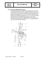
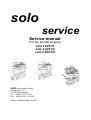
solo
service
Service-manual
For the aircraft engines
solo 2 625 01
solo 2 625 02
solo 2 625 02i
solo Kleinmotoren GmbH
Stuttgarter Str. 41
D 71069 Sindelfingen
Tel.: (0049) 7031 - 3010
Fax.: (0049) 7031 – 301195
Edition 2 dated October 1st.2010
Baureihe
2 625 01
2 625 02
2 625 02 i
Service Manual
SOLO
KLEINMOTOREN
GMBH
Table of contents
1
2
3
4
4.1
4.2
4.3
4.4
4.5
4.5.1
4.5.2
4.5.3
4.6
4.6.1
4.6.2
4.7
4.7.1
4.7.2
4.7.3
4.7.4
4.8
4.8.1
4.8.2
4.8.3
4.8.4
5
6
1
General hints and description of the engines ............................................................ 2
Necessary tools ........................................................................................................ 4
Disassembly of the engine ........................................................................................ 5
Check of the individual parts ..................................................................................... 6
Cylinder heads.......................................................................................................... 6
Cylinders................................................................................................................... 6
Piston and piston rings ............................................................................................. 6
Crankshaft ................................................................................................................ 7
Ignition system.......................................................................................................... 7
Engines 2625 01 and 2625 02 .................................................................................. 7
Troubleshooting ignition systems.............................................................................. 8
Wire diagrams Iskra and ducati ignition systems ...................................................... 9
Engine Control Unit (ECU)...................................................................................... 10
Wire diagram ECU 2625 02 i .................................................................................. 10
Wire diagram redundancy system of the engine 2625 02 i ..................................... 11
Carburettor.............................................................................................................. 12
Specialties MIKUNI BN 38 ..................................................................................... 12
Specialties MIKUNI BN 38-34-55............................................................................ 13
Adjustment of the carburettors ................................................................................ 14
Troubleshooting at the carburettors ........................................................................ 15
Trouble shooting at the fuel injection system (only 2625 02 i) ................................ 16
Engine does not start .............................................................................................. 16
Failures during operation ........................................................................................ 16
Failure memory ....................................................................................................... 16
Software for the ECU .............................................................................................. 16
Assembly of the engine........................................................................................... 18
Notes....................................................................................................................... 20
General hints and description of the engines
This service – manual shall give the engine specialist necessary hints for repairs and
overhauls for the engine and help him solving specific problems. General knowledge
of two-stroke-engines should be present.
This Service-manual is valid together with the engine-manual and the spare-partslist.
! Attention!
Because this engine is used as a certified engine for motor gliders the national
authorizations of the specific certifying staffs must be maintained.
edition 2 dated 1.10.2009
Seite 2
Baureihe
2 625 01
2 625 02
2 625 02 i
Service Manual
SOLO
KLEINMOTOREN
GMBH
Description of the engines
The aircraft engines 2625 01, 2625 02 and 2625 02i are based on the same engine
block and differ only by different carburetors or at the engine 2 625 02i by the use of
an electronic fuel injection. The engines 2625 02 and 2625 02i have a different
cylinder with a different port timing of the intake port. All three engines are watercooled two cylinder two-stroke engines with piston-ports. They have a displacement
of 625 cm3 with a stroke of 69 mm and a bore of 76 mm. They are lubricated by a
fuel-oil mixture. For all engines a breaker less double ignition is used.
Aircraft engine 2625 01
This engine has one diaphragm carburetor, which feeds both cylinders and a take-off
power of 39 kW at a speed of 6.250 RPM.
Aircraft engine 2625 02
This engine has a different intake-port timing compared to the engine 01 and two
diaphragm carburetors. The take-off power is 47 kW at a speed of 6.500 RPM
Aircraft engine 2625 02i
This engine is based on the engine 2625 02, which is converted according to the
Service bulletin TM 4603 – 3 to the version with electronic fuel injection. The
carburetors and the ignition system are replaced by this electronic fuel injection
system into the manifolds and also by an electronic ignition system. The former
ignition system is replaced by an alternator, which supplies sufficient electric energy
to operate the fuel injection and the ignition. The take-off power is 50 kW by a speed
of 6.500 RPM.
An ECU is controlling the injected amount of fuel and the ignition timing based on the
engine speed, the position of the throttle valve, the engine temperature, the ambient
pressure and the outside air temperature. This guaranties that the engine is running
under optimal conditions.
In order to achieve maximum security in case of a breakdown of the ECU a simple
redundancy system is installed, which supplies the engine with two additional
injection valves. An ignition module which is driving the two coils of the engine is
integrated in this system. The system is controlled by an additional RPM-sensor.
Other sensors are not necessary.
The engine management system is consisting of the following components:
•
•
•
Pre-filter, fuel pump, micro filter and fuel pressure regulator for the fuel supply.
The fuel pressure in the system is regulated by the pressure regulator at 3
bars. The fuel line from the pressure regulator back to the fuel tank is pressure
less.
Engine Control Unit with ignition modules and a pressure sensor, which
measures the atmospheric pressure. In the ECU the maps for fuel injection
and ignition timing are stored. Based on the air pressure and the air
temperature the ECU calculates the correct amount of injected fuel.
The engine has 5 sensors. Facing the flywheel of the alternator there is an
RPM sensor. At the throttle valve there is a sensor, which measures the
opening of the shutter valve. At the rear cylinder head there is a temperature
sensor measuring the coolant temperature. Near the air filters there is a
edition 2 dated 1.10.2009
Seite 3
Baureihe
2 625 01
2 625 02
2 625 02 i
•
•
Service Manual
SOLO
KLEINMOTOREN
GMBH
sensor measuring the intake air temperature. In the ECU there is a pressure
sensor measuring the atmospheric pressure.
A double throttle valve assembly and one injection valve each, which are
controlled by the ECU.
Two double ignition coils with ignition wires leading to the front and rear
cylinder each. The engine is running with minimal power loss fired by only one
coil.
If a sensor fails or a wire breaks standard values are stored in the ECU which
guarantee a limited operation of the engine. Only if the speed sensor fails the engine
stops. The ECU supplies constantly values about speed, temperatures and the
condition of the sensors via a CAN-bus, which can be displayed to the pilot. In
addition to that there is a failure memory, which can be read by the manufacturer.
With this memory it can be detected, if one or more values have exceeded their
limits. Short above the maximum engine speed the ignition is cut off. The starting of
the engine must always be in idle position. A choke or other fuel enrichment systems
are not necessary. The ECU has a serial interface, which allows the detection of the
status of the ECU in operation. Special software is necessary for that. The settings
and the access to the failure memory are protected by a password.
2 Necessary tools
In order to conduct an expert repair or check it is necessary to use functional tools in
good condition. Except the usual tools, present in each engine workshop the
following special tools are necessary.
Pos.
SOLO order No.
1
2
3
4
00 80 529
00 80 530
00 80 314
5
6
7
8
00 83 177
edition 2 dated 1.10.2009
Description
Puller for hub
Puller for Ignition flywheel
Pressure tester
Two stroke oil Castrol ACT>EVO, Castrol Super Two
Stroke, Other oils with specification JASO FC or FD
Air filter oil
Loctite 274
Loctite 270
Loctite 574
Seite 4
Baureihe
2 625 01
2 625 02
2 625 02 i
Service Manual
SOLO
KLEINMOTOREN
GMBH
3 Disassembly of the engine
Pos.
1
2
3
4
5
6
7
8
9
10
11
12
13
Operation
Clean engine before disassembly
Disassemble carburetor from manifold
Disassemble muffler, clean muffler from debris
and coal.
Loosen flywheel of the ignition system and pull
off flywheel with suitable puller.
Disassemble the stator of the ignition system
completely. If the engine has an ignition
system from Ducati disassemble also the plate
with the pick-ups.
Loosen hub at the front end of the crankshaft
and pull off with the suitable puller.
Loosen nuts at the cylinder head.
Lift cylinder head.
Mark cylinder head, cylinder and piston for
matching.
Loosen nuts at the bottom of the cylinder and
lift cylinder carefully.
Disassemble the piston-pin lock carefully. Push
piston-pin out of the piston by hand.
Loosen the 4 bolts on the side of the crankcase
and move the two halves of the crankcase
apart carefully so that they don’t get out of line.
Clean both parts.
ATTENTION! ON ENGINES WITH DOUBLE
BEARING ON THE DRIVE SIDE LOOSEN THE
FOUR BOLTS AT THE FRONT-END FIRST.
Take off seals, locks and outer rings of the
roller bearings by hand.
edition 2 dated 1.10.2009
Seite 5
Tools, aid
Use fuel
Open end spanner 13 mm
Allen key 6 mm
Puller SOLO-No. 00 80 530
Socket wrench 19 mm
Puller SOLO No. 00 80 529
Socket wrench 13 mm
Open end spanner 12 mm
Baureihe
2 625 01
2 625 02
2 625 02 i
Service Manual
SOLO
KLEINMOTOREN
GMBH
4 Check of the individual parts
4.1 Cylinder heads
•
•
•
Clean the inside part of the cylinder head from coal. Fuel can dissolute rests of
burnt oil. Heavy oil-carbon deposit can be removed with a steel brush.
Check both threads for the spark-plugs if damaged
Clean the sealing surface.
4.2 Cylinders
•
•
Check the cylinder surface (Coating) visually if there are damages
(Scratches).
Check the diameter of the cylinder in direction of the crankshaft and
rectangular:
Dimension
10 mm below top
30 mm below top
25 mm above bottom
•
•
•
New
76 mm +/- 0,005
76,mm +/- 0,005
76 mm +0,01
Wear limit
76,01 mm
76,01 mm
76,02 mm
Check visually the grooves for the o-rings at the top of the cylinder.
Check the entire cylinder for cracks or damages of the sealing surfaces.
Remove oil-carbon deposit on the coating and in the exhaust port.
4.3 Piston and piston rings
•
•
Remove oil-carbon deposit on the piston top carefully.
Check piston diameter. Measure the diameter rectangular to the piston pin
boss.
Dimension
D1=DN 22 mm above
bottom
D2: 59,5 mm above
bottom
D3: 69 mm above
bottom
•
•
New
76 mm +/- 0,06
Wear limit
75,9 mm
76 mm +/- 0,08
75,8 mm
76 mm - 0,093
75,7 mm
Check vertical play of the piston rings
New 0,05 mm - 0,10 mm
wear limit 0,20 mm
Check wear of the piston rings.
Distance between the two ends if the piston ring is mounted into the cylinder:
New 0,2 - 0,35 mm
wear limit 0,8 mm
No light has to be seen between cylinder wall and piston ring if the cylinder is
hold against a lamp.
edition 2 dated 1.10.2009
Seite 6
Baureihe
2 625 01
2 625 02
2 625 02 i
Service Manual
SOLO
KLEINMOTOREN
GMBH
4.4 Crankshaft
The Crankshaft can be disassembled only by the manufacturer.
The main bearings at the drive side or the ignition side (roller bearings) can be
replaced. To conduct this, the inner rings must be grinded carefully on one spot until
only 0.3 mm of wall thickness is left. Then they can be cracked by using a chisel.
After that they can be slipped off the shaft.
• Check true running on a centering device. The eccentricity at the bearings should
not exceed 0.04 mm. If the eccentricity is more the crankshaft can be adjusted by
the manufacturer.
• Check axial play at the con-rod bearings.
The play must be between 0.35 und 0.5 mm.
4.5 Ignition system
4.5.1 Engines 2625 01 and 2625 02
Following ignition systems are used:
•
ISKRA – Magneto Ignition with generator 12 V, 70 W for the engine 2 625
01 up to serial-No. 12.
•
DUCATI - Magneto Ignition with generator 12 V, 150 W for the engine 2
625 02 from serial-No. 1 and for the engine 2 625 01 from serial-No. 13.
Both ignition systems have two independent ignition circuits.
4.5.1.1
Specialties of the Iskra ignition system
This ignition system has a stator which can be adjusted on the crankcase.
The proper ignition timing is adjusted if the stator is turned as far as
possible against the rotational direction of the engine (anti clockwise).
The ignition timing can only be checked with a strobe light while the engine
is running in idle.
4.5.1.2
Specialties of the Ducati ignition system
The ignition timing is fixed and cannot be adjusted. The proper position of
the external pick-ups for the two circuits stand for the ignition timing.
The ignition timing (22 ° BTDC) can be checked with the strobe light while
the engine is running in idle. Therefore there are marks on the pick-ups
and the rotor which have to match. Then the correct angle can be checked
statically.
edition 2 dated 1.10.2009
Seite 7
Baureihe
2 625 01
2 625 02
2 625 02 i
4.5.2
Service Manual
SOLO
KLEINMOTOREN
GMBH
Troubleshooting ignition systems
• No spark on one Ignition circuit
o Wire defect on one wire from the pick-ups or at a wire to the ignition
coil.
o Wire from one pick-up to the ignition coil has connection to ground.
o The shut-off-wire for one circuit has connection to ground
o The relating ignition coil has a defect. This can be checked if the wires
to coil 1 are exchanged with the ones to coil 2. If the defect is moving
to the other circuit the coil has to be replaced.
o If the defect is not moving then a coil in the stator or one of the pickups have to be replaced.
• No spark on both ignition circuits
o Wire defect at the wires to the ignition coils.
o Wires from the pick-ups or from the generator coils to the ignition coils
have connection to ground.
o Shut-Off-wires have connection to ground.
• No charging current
o
o
o
o
Wire defect at the wires from the coils to the stabilizer.
Wires to the stabilizer have connection to ground.
Plugs at the stabilizer have a defect.
Are all previous defects not present the stabilizer has to be replaced.
edition 2 dated 1.10.2009
Seite 8
Baureihe
2 625 01
2 625 02
2 625 02 i
Service Manual
SOLO
KLEINMOTOREN
GMBH
4.5.3 Wire diagrams Iskra and ducati ignition systems
•
Iskra ignition system
•
Ducati ignition system
edition 2 dated 1.10.2009
Seite 9
Baureihe
2 625 01
2 625 02
2 625 02 i
SOLO
Service Manual
KLEINMOTOREN
GMBH
4.6 Engine Control Unit (ECU)
The following wire diagram shows the connection between the ECU and the various
components of the engine. The functions of the ECU where described in chapter 1.
The wire diagram of the redundancy system is shown below.
4.6.1 Wire diagram ECU 2625 02 i
15 ●
CANH CANL
● ●
25
7
Butterfly valve
4
●
2
●
31
─
Computer interface
2 3 5
● ● ●
3
●
▼
▼
IV2
IV1
26 Txd
35
1
1
20
─
2
─
17
8 Rxd
─
─
─
─
─
─
─
─
─
─
─
─
─
─
─
─
─
19
20
─
─
─
─
─
─
─
─
─
─
─
─
─
─
─
─
─
─
37
38
─
─
─
─
─
─
─
─
─
─
─
─
─
─
─
─
─
─
55
36
54
37
55
Shielded
21
3
41
4
+
42
4
-
+
IC
1
10
52
─
IC
2
53
─
●
●
Ignition switch
Relay
─
─
─
T-Air
31
Ground
T-Water
─ ●
31 15
Ground
4
HV
●
15
+
4
HV
●
30
+
●
15
─
31
+
─
Fuel pump
15 = Switched positive
30 = Continous positive
31 = Ground
4 = High voltage ignition wire
Ground throttle valve transducer
5 Volts throttle valve transducer
Signal throttle valve transducer
7
25
CAN L
CAN H
8
26
Computer interface Rxd
Computer interface Txd
17
35
Injection valve 1 (Alternator side)
Injection valve 2 (Drive side)
21
3
Temperature transducer air
Temperature transducer coolant
(CAN bus)
(CAN bus)
edition 2 dated 1.10.2009
─
31
41
42
Ignition coil 1 (Alternator side)
Ignition coil 2 (Drive side)
10
Relay fuel pump
53
54
RPM transducer (Induktive)
Ground RPM transducer
36
54
Ground
Ground
37
55
Switched positive
Switched positive
18
Continous positive
Seite 10
30
+
31
─
Battery
Plug connection ECU
1
20
2
18
∩
Ind. Sensor
─
31
Baureihe
2 625 01
2 625 02
2 625 02 i
SOLO
Service Manual
KLEINMOTOREN
GMBH
4.6.2 Wire diagram redundancy system of the engine 2625 02 i
GND
─
GND
─
GND
─
BAT
─
BAT
─
RPM
─
ZS
─
ZS
─
EV
─
▼
▼
IV2
IV1
31 ─
─
● 15
4
+
4
-
+
IC
1
─
IC
2
─
●
●
Ignition switch
Relay
─
─
●
15
●
30
Ind. Sensor
─
31
●
30
15 = Switched positive
30 = Permanent positive
31 = Ground
4 = High voltage ignition wire
4
HV
●
30
+
4
HV
●
30
+
─
31
+
─
Fuel pump
:Switched positive
:Switched positive
GND
GND
:Ground
:Ground
EV
:Injection valve 1 and 2
ZS
ZS
:Ignition coil
:Ignition coil
RPM
GND
:RPM sensor
:Ground RPM sensor
edition 2 dated 1.10.2009
Seite 11
31
─
Battery
─
31
Steckerbelegung TBD
BAT
BAT
30
+
─
31
Baureihe
2 625 01
2 625 02
2 625 02 i
Service Manual
SOLO
KLEINMOTOREN
GMBH
4.7 Carburettor
Two types of carburetors are used:
•
MIKUNI BN 38 Diaphragm carburetor without fuel-pump
•
MIKUNI BN 38 - 34 - 55 Diaphragm carburetor without fuel-pump
The engine 2 625 01 has one carburetor.
The engine 2 625 02 has two carburetors.
4.7.1 Specialties MIKUNI BN 38
The carburetor has an integrated main jet which controls about 75% of
the fuel at wide open throttle. This jet cannot be changed. Any fine
adjustment can be conducted with the needle marked with “H”. The
normal setting of that needle is one turn open. Typically the setting
should be slightly leaner (7/8 turns open).
The low-speed needle is marked with „L“. The typical setting is ½ turn
open and should not be changed.
edition 2 dated 1.10.2009
Seite 12
Baureihe
2 625 01
2 625 02
2 625 02 i
Service Manual
SOLO
KLEINMOTOREN
GMBH
4.7.2 Specialties MIKUNI BN 38-34-55
The carburetor has an exchangeable main-jet marked for 2 625 01 by
127.5 (engine 2625 02 has 117.5). This jet controls 75% of the fuel at
wide open throttle. The carburetor is adjusted by the manufacturer in a
way that the needle which is accessible from outside (marked “H”) the
engine can be adjusted leaner up to ¼ of a turn. The needle-top has a
plastic part which allows an adjustment of ¼ of a turn only. The needle
must be in the left (counterclockwise) end position. The leaner
adjustment is only necessary on airfields above 1.000 m above sea
level. The low-speed needle is marked with „L“. The typical setting is ½
turn open and should not be changed.
edition 2 dated 1.10.2009
Seite 13
Baureihe
2 625 01
2 625 02
2 625 02 i
Service Manual
SOLO
KLEINMOTOREN
GMBH
4.7.3 Adjustment of the carburettors
The adjustment is almost identical with both types of carburettors. Before you
start the basic needle adjustment should be made (see chapter 4.6.1 and
4.6.2).
Engine 2 625 01 with one carburettor
•
•
•
•
The Exhaust gas temperature (EGT) can be measured through a hole
in the exhaust manifold which is shaped like a Y 100 mm after the
cylinder flange with a Ni-CrNi thermo-couple. It is enough to measure in
one of the two legs of the manifold.
Start the engine and warm up the engine until the water reaches a
temperature of 40°C.
Adjust the idle speed with the idle speed screw until the engine runs
between 2.300 and 2.600 RPM.
At wide open throttle measure the EGT and wait until that temperature
reaches a stable max. value. (After approx. 3 minutes). The carburetor
should be adjusted so that the EGT is between 630 and 640 °C. Don’t
adjust too early because you then could set the carburetor too lean.
Engine 2 625 02 with two carburettors
•
•
•
•
•
•
The carburetor adjustment is almost identical for both types.
The typical setting should be made first. (see above „specialties“)
The Exhaust gas temperature (EGT) can be measured through a hole
in the exhaust manifold which is shaped like a Y 100 mm after the
cylinder flange with a Ni-CrNi thermo-couple. It is necessary to measure
in both legs of the manifold.
Start the engine and warm up the engine until the water reaches a
temperature of 40°C.
Adjust the idle speed with the idle speed screw until the engine runs
between 2.300 and 2.600 RPM. Both idle speed screws should be
adjusted so that the EGTs reach 230 °C +- 20°C. In order to have a
good start the air filters can be removed first and the two throttles can
be so adjusted that the opening angle is identical at 1 mm open.
At wide open throttle measure the EGT and wait until that temperature
reaches a stable max. value. (After approx. 3 minutes). The carburetor
should be adjusted so that the EGT is between 630 and 640 °C. Don’t
adjust too early because you then could set the carburetor too lean.
The difference between the two EGTs should not exceed 30°C.
edition 2 dated 1.10.2009
Seite 14
Baureihe
2 625 01
2 625 02
2 625 02 i
Service Manual
SOLO
KLEINMOTOREN
GMBH
4.7.4 Troubleshooting at the carburettors
• Setting too lean
Lean setting can be detected if the engine does not accelerate properly or
if the EGT is too high.
o Check typical setting of the adjustment needles first.
o Clean the carburettor after removing the diaphragm-cover. The
clean remove idle and high speed adjustment screws. Clean all
openings with pressurized air. Clean also the fuel inlet with
pressurized air.
o After reassembly of the inlet needle the proper sealing of the
valve has to be checked. It is necessary to use the pressure
tester (see above). Disconnect the fuel line and apply 0.4 bar of
pressure to the carburetor. The pressure-loss should not accede
0.1 bars per minute. If an electric fuel pump is installed, the
check can be conducted with this pump. First remove the
diaphragm cover and switch on the pump. No fuel should flow
out of the valve.
o Adjust the carburetor as described above.
•
Setting too rich
Rich setting can be detected if power is low (RPM), shaking of the engine
and loss of RPM below 3.000 m above sea level.
o Check typical setting of the adjustment needles first.
o Replace air-filter or clean filter mesh (wash with fuel and dry with
compressed air)
o Check the proper sealing of the inlet valve. It is necessary to use
the pressure tester (see above). Disconnect the fuel line and
apply 0.4 bar of pressure to the carburetor. The pressure-loss
should not accede 0.1 bars per minute. If an electric fuel pump is
installed, the check can be conducted with this pump. First
remove the diaphragm cover and switch on the pump. No fuel
should flow out of the valve.
o Adjust the carburetor as described above.
edition 2 dated 1.10.2009
Seite 15
Baureihe
2 625 01
2 625 02
2 625 02 i
Service Manual
SOLO
KLEINMOTOREN
GMBH
4.8 Trouble shooting at the fuel injection system (only 2625 02 i)
4.8.1 Engine does not start
No fuel
Check the fuel lines and the function of the fuel pump.
No spark at both spark
plugs
Weak battery, charge the battery.
Broken wire
No spark at one spark
plug
Spark plug defect. Ignition coil defect. Ignition wire broken.
4.8.2 Failures during operation
Engine overheats
Not enough coolant. Water pump defect. Fuel pressure not
sufficient.
Engine does not reach Fuel pressure not sufficient. Fuel filter clogged. Throttle
full power
valve does not open completely. Spark plugs defect.
Fuel pump defect.
4.8.3 Failure memory
The ECU has a failure memory, which detects failures at the system and stores
them. Only the manufacturer can read the memory. For an analysis the ECU has to
be sent to the manufacturer.
4.8.4 Software for the ECU
On the page http://www.trijekt.de/downloads-10.html software (Win trijekt) can be
downloaded, which allows to connect a computer to the serial interface of the ECU.
After installing the software the status of the ECU can be checked. Connect the serial
cable to the computer and the ECU and start the software. Then switch the ignition
(ECU) to “ON”. If the software shows „connected“the status of the sensors and the
ECU can be checked.
edition 2 dated 1.10.2009
Seite 16
Baureihe
2 625 01
2 625 02
2 625 02 i
Service Manual
SOLO
KLEINMOTOREN
GMBH
The status window shows the status of the sensors, the injection time and the ignition
angle during engine operation.
Check the following indications:
No. Of rev. errors:
If the number of rev. Errors increases during starting or engine operation, a failure of
the speed sensor can be indicated. Check sensor and wires.
Throttle potentiometer
In idle position the value should be around 10 degrees and during full throttle 90
degrees. With other readings the sensor is defect.
Engine temperature
Check the engine temperature with a second gauge if it is plausible.
Air temperature
Check the air temperature with a second gauge if it is plausible.
Air pressure (int.)
This value can be checked with an altimeter.
Other sensors are not connected.
edition 2 dated 1.10.2009
Seite 17
Baureihe
2 625 01
2 625 02
2 625 02 i
Service Manual
SOLO
KLEINMOTOREN
GMBH
5 Assembly of the engine
Before assembly apply two-stroke oil on crankshaft bearings, pistons and piston
pins.
Operation
1
2
3
4
5
6
7
8
9
Tool, aid
Heat inner rings of roller bearings up to 180°C
And slip on free ends of the crankshaft. The
flange of these rings has to be next to the
crank web.
Attention! For engines with double bearing first
slip on the ring with flange, then the spacer ring
and then the ring without flange. All three rings
must be positioned next to each other.
Clean crankcase with thinner. Remove
possible rests of former gaskets completely.
Apply Loctite 574 on contact surfaces of the
crankcase halves and put crankshaft into the
lower half. Before that apply two-stroke oil on
all bearings. Assemble all rings and seals
together with the crankshaft.
Mount other half of the crankcase plus the 4
bolts on both sides with Loctite and tighten with
a torque wrench.
Attention! On engines with double bearings
mount the steel liner with the two lower bolts
first. Then tighten the four bolts on the sides of
the crankcase. Then tighten the 4 bolts on the
front of the steel liner. Apply Loctite 274 on all
bolts.
Assemble piston with rings to the connecting
rod and secure with piston-pin locks. Push
piston pin into piston by hand. Apply two-stroke
oil on all parts.
Mount cylinders and mount nuts M8 so that the
cylinders are still movable.
Assemble intake manifold on engine 2 625 01
or exhaust manifold on engine 2 625 02 with
gaskets in order to get cylinders in line. Then
tighten the 4 nuts on each cylinder.
Assemble cylinder heads
Heating plate with temperature
control
Loctite 574
Two-stroke oil
Torque wrench (12 Nm)
Loctite 274
Piston ring clamp bent out of
spring steel
Torque wrench
(20 Nm)
Torque wrench (20 Nm)
Plug all openings (Intake and exhaust ports) Pressure tester
with steel parts and rubber parts in the shape
of the flanges. Check if the engine block is
sealed with 0.5 bar pressure. Pressure loss
edition 2 dated 1.10.2009
Seite 18
Baureihe
2 625 01
2 625 02
2 625 02 i
Service Manual
SOLO
KLEINMOTOREN
GMBH
should not exceed 0.1 bars per minute.
10
12
Assemble stator of the ignition system. Secure
all bolts with Loctite.
Assemble flywheel. Clean cone and flywheel
with thinner first.
Assemble exhaust manifold with gaskets.
13
Assemble carburettor on intake manifold.
14
Assemble air filter on carburettor.
15
Check sealing of the cooling system with a Pressure tester
pressure of 1 bar. No pressure loss allowed.
11
edition 2 dated 1.10.2009
Seite 19
Torque wrench (12 Nm)
Loctite 270
Torque wrench (80 Nm)
Torque wrench (20 Nm)
Loctite 270
Baureihe
2 625 01
2 625 02
2 625 02 i
Service Manual
6 Notes
edition 2 dated 1.10.2009
Seite 20
SOLO
KLEINMOTOREN
GMBH