1
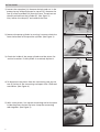
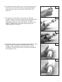
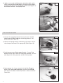
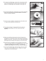
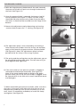
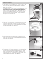
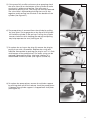
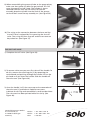
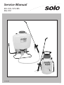
Service Manual
425 / 435 / 475 /485
456 / 457
9 425 300
1
CONTENTS
OPERATING DISCRIPTION
Specifications
Page
Technical Data
Operating Description
425/435/475/485
Operating Description
456/457
Backpack Sprayer
Trouble Shooting Guide
Piston Pump
Diaphragm Pump
Pressure cylinder
Handheld Sprayer
Trouble Shooting Guide
Handheld Sprayer
Shut-off valve
2
2
2
3
4
6
8
9
10
12
OPERATING DESCRIPTION
Compression Sprayer 456, 457
During the upward stroke, the o-ring on the plunger
moves to the fluted side of the o-ring groove and
allows air to be drawn past the o-ring and into the
pump cylinder. On the downward stroke, the o-ring
presses against the solid side of the o-ring groove
and blocks air from escaping past the o-ring. As the
downward stroke continues, air is compressed in the
pump cylinder and is expelled past the check valve on
the bottom of the cylinder and into the tank. As
more air is pumped into the tank, the pressure is
increased. Pressure in excess of 45 PSI is released
through the spring loaded pressure relief valve.
When the shut off valve is opened, liquid is forced
through a pick-up tube in the spray tank. From the
pick-up tube, the liquid travels through the hose,
shut-off valve and finally out the nozzle.
Backpack Sprayers 425, 435, 475, 485
During the upward stroke of the handle on either
the piston or diaphragm, liquid is drawn from the
formula tank through the intake channel into the
space above the pump. The lower valve plate opens
intake channel while the upper valve plate closes the
transfer ports. During subsequent upward stroke of
piston or diaphragm, the previously siphoned liquid
is forced through the four transfer ports and into the
pressure cylinder. During this compression phase, the
upper valve plate opens the transfer ports and the
lower valve plate closes, sealing the intake channel.
The transfer ports cannot be sealed by the lower
valve plate.
Through repetition of these piston or diaphragm
strokes, the air present in the pressure cylinder is
beeing slowly compressed by the forced-in liquid.
A prerequisite for this condition is a closed shut-off
valve. These pumping strokes can be carried out so
long until the required pressure is reached.
After opening the shut-off valve, continue to pump
slowly and steadily in order to achieve a consistent
rate of discharge.
TECHNICAL DATA
425
475
456
457
Weight, Empty
Tank capacity
Pump system
Pressure Chamber
Displacement
(Pump Cylinder)
Operating pressure
Total Height
Total Width
Depth
9.5 Lbs 4,3 Kg
4 US Gal 15 L
Piston
1.4 US Q/ 1,3 L
9.5Lbs 4,3 Kg
4 US Gal 15 L
Diaphragm
1.4 US Q/ 1,3 L
5.5 Lbs 2,5 Kg
1. 5 US Gal 5,0 L
Piston
N/A
6.5 Lbs 3,5 Kg
2 US Gal 7,5 L
Piston
N/A
4.9 CU IN
90 PSI 6 ATM
21 IN
13.75 IN
8.25 IN
4.9 CU IN
60 PSI 4 ATM
21 IN
13.75 IN
8.25 IN
21.1 CU IN
45 PSI 3 ATM
17.25 IN
8.25 IN
N/A
21.1 CU IN
45 PSI 3 ATM
23 IN
8.25 IN
N/A
2
BACKPACK SPRAYER TROUBLE SHOOTING GUIDE
PROBLEM
CAUSE
SOLUTION
Difficulty In moving Pump lever
Dirty bushing
Collar swollen (425) from long
term exposure
Remove pump lever, clean &
grease bushings
Remove piston, clean/ replace
piston & collar
Replace collar and maintain
according to instructions
Lack of lubrication (425).
Lubricate viton collar
Damaged/ dirty valve plates
Damaged o-ring at valve seat
Clean or replace valve plates or
cylinder
Replace o-ring
Collar or piston (425) worn
Replace collar or piston
Sealing in pressure regulator
is leaking
Check seal and valve seat
High resistance after just a few
pumping strokes, pressure lasts
only briefly
Little or no air cushion in
pressure cylinder
Remove PVC hose, drain
pressure cylinder, reconnect
hose, preventive measure:
release pressure after each use
During Spraying, upward
pumping becomes more &
more difficult and tank walls
may indent inwards.
Wrong formula tank cap
(No vent hole)
Replace with vented cap
Vent hole clogged
Clean vent hole
Lower valve plate sticks
Replace valve plate
Intake channels clogged
Clean channels & tank
When handle is pulled up it
wants to move itself forcibly
back down.
Screen at base of pressure
cylinder clogged
Clean intake screen with a
small brush and detergent
Leaks inside cylinder (425)
Damaged/ dirty collar or piston
Leaks outside cylinder (425)
Damaged o-ring on cylinder
Clean or replace collar and
possibly cylinder if worn
Replace o-ring
Dirty cylinder walls (425).
Insufficient resistance during
repeated pumping
and no pressure
Leaks on diaphragm pump (475)
Leaks from end of spray Wand
Damaged o-ring on pressure
cylinder
Replace o-ring
Damaged diaphragm
Replace diaphragm
Damaged o-ring on diaphragm
housing
Replace o-ring
Damaged o-ring on pressure
cylinder
Worn or damaged shut-off
valve
Replace o-ring
Inspect and rebuild shut-off
valve
3
PISTON PUMP
1) Loosen the stop plate (A). Remove the bolt and nut in the
protective cap and pull protective cap off (C). Remove the
two (2) allen head bolts (D) from the lever. The piston can
then be pulled from the cylinder (E). (See figure 1).
Also, loosen the clamp (F) and remove the hose.
Fig. 1
2) Remove the pump cylinder by turning it counter-clockwise
from the bottom of the pressure cylinder. (See figure 2).
Fig. 2
3) Check the inside of the pump cylinder and the piston for
vertical scratches. If the cylinder is scratched, replace it.
Fig. 3
4) To disconnect the piston from the connecting rod, pry the
two (2) halves of the connecting rod apart with a flathead
screwdriver. (See Figure 4)
Fig. 4
5) With a new piston, line up the connecting rod on the posts
inside the piston and on the lever. Snap the connecting
rods together. (See Figure 5).
Fig. 5
4
6) To replace the Viton collar, push it off with the top of the
piston with your thumb. The new one is simply pushed
over the piston crown into the form fitted sides. (See
Figure 6).
7) To replace the valve plates and o-rings on the pump
cylinder: remove the outer o-rings, the top valve plate and
replace. The lower valve plate (inside the cylinder) is
replaced by pulling out the retaining pin. Use pliers. (See
Figure 7). Replace the valve plate and then push the
holding pin back into place.
Fig. 6
Fig. 7
Fig. 8
8) The pump cylinder screws into the pressure cylinder. A little
grease on the o-ring makes reassembly easier. Screw
cylinder in tight, and be sure that the notch on pumpcylinder (A) is lined up with catch on pressure cylinder (B).
(See Figures 9 & 10)
Fig. 9
Fig. 10
5
9) Apply a non-water soluble grease (petroleum jelly works
well) arround the outside edge of the Viton collar before
installing the piston into the pump cylinder. (See figure 12).
Re-connect the lever to the pump rod.
GREASE
HERE
Fig. 11
Fig. 12
THE DIAPHRAGM PUMP
1) Loosen the stop plate (A) and remove the two (2) allen
head screws (B) that hold the connecting pieces to the
pump rod. (See Figure 13)
Fig. 13
D
E
2) Remove the pump rod (C) and the hose (D). Next, loosen
the clamp at the base of the sprayer (E). (See Figure 13)
A
C
3) Push the pressure cylinder approximately 1“ out of the
bottom of the tank. Then turn the pump assembly 1/2 turn.
(See Figure 14). Push pressure cylinder from sprayer.
B
Fig. 14
Fig. 15
4) Next remove the 12 torx screws that hold the flange in
place. The flange and diaphragm can then be removed.
(See Figure 15). Note: Pressure cylinder is shown removed
from tank.
6
5) To replace the diaphragm, remove the connecting rod (G)
from the backing plate by removing the retaining screw.
Replace the diaphragm and reassemble. (See Figure 16)
Fig. 16
G
Fig. 17
6) The valve assembly (H) is removed using a locally produced
special tool (See drawing for measurements). The valve
unscrews counter-clockwise.
H
7) Once the valve assembly is removed, the valve plates and
o- rings can be replaced. (See Figure 18).
Fig. 18
8) The pump housing (L) is separated from the pressure
cylinder (J) by pulling it off. The o-ring can then be
replaced.
Fig. 19
J
L
9) When reassembling the pump housing to the pressure
cylinder, be sure the square tab on the pump housing (K) is
aligned in the notch - (see arrows (L)) on the pump cylinder.
(See Figure 20). Be careful not to pinch or nick the o-ring.
Fig. 20
10) Screw the valve assembly into the cylinder. Be sure that
the two (2) square holes the threaded portion of the valve
assembly are aligned with the holes in the pressure
cylinder. Look through the inlet screen to check alignment.
11) Re-install the diaphragm and the flange with the twelve
(12) screws. Push assembly into tank. Tighten the large
clamp and re-install other parts.
7
THE PRESSURE CYLINDER
Fig. 21
1) With the large clamp at the bottom of the tank removed,
the pressure cylinder will push out through the bottom of
the tank. (See Figure 21).
2) Once the pump cylinder is removed, the large o-ring (A)
can be replaced. (See Figure 21). Note: The new o-ring
should be slid onto the pressure cylinder from the top to
the recess. It should not be streched over the flange at the
bottom.
3) Remove the adjustment cap by depressing and turning
counter-clockwise past the “1“ setting. (See Figure 22).
Fig. 22
4) The adjustment piece is then removed by unscrewing it
from the pressure cylinder. Once the o-rings are replaced,
apply a small amount of grease to them and reassemble.
(See Figure 23). Note: The adjustement piece has been
painted white for clarity of the o-rings in photo.
Fig. 23
5) The spring and the sealing piece on the adjustment cap can
be removed by pulling them apart. The new ones will just
push together. (See Figure 24).
Fig. 24
6) If the inlet screen on the pressure cylinder is clogged, it
should be cleaned before reassembly. (See Figure 25)
Note: If the pump handle tends to spring to the down
position when you lift up, the inlet screen is clogged. It can
be cleaned while in the tank with a small hard bristle brush
and detergent.
Fig. 25
7) When reassembling the pressure cylinder, make sure the oring stays in the recess. Also make sure that the cut out on
the pressure cylinder (B) lines up with the notch (C) on the
tank. Once it is completely assembled, re-install the clamp
and tighten. (See Figure 26).
Fig. 26
B
B
8
HANDHELD SPRAYER TROUBLE SHOOTING GUIDE
PROBLEM
CAUSE
SOLUTION
Difficulty in moving pump
handle
Dirty cylinder wall
Remove piston, clean and
replace
Low pressure & resistance
during pumping
O-ring on piston swollen
(Not cleaned properly)
Replace o-ring
No lube on piston/ cylinder
Lubricate with heavy grease
Check valve not sealing or
missing
Check & replace if necessary
Damaged o-ring in relief valve
Replace o-ring
Worn or damaged o-ring on
piston
Replace o-ring
Tighten cap
Tank cap not tight
No lube on piston cylinder
Lubricate piston, o-ring and
cylinder
Leaks from end of spray wand
Worn or damaged o-ring in
shut-off valve
Rebuild shut-off valve
Leaks from inside cylinder
Worn or damaged o-rings on
bottom of cylinder
Replace o.ring and valve cone
Leaks under cap
Damaged or missing gasket
Replace gasket
Screw cap not tight
Pressurize unit, tighten caps
until leaks stop
Leaks from shut-off valve
Worn, Damaged or Loose
fittings
Tighten fittings and replace
worn parts
Leaks from hose
Worn, Damaged or Loose
fittings
Tighten fittings and replace
worn parts
Pressure release valve sticks
Lack of lubrication or
contaminated release valve
assembly
Clean and lubricate pressure
release valve
Air leak - Air coming out
between the two halves of the
pump support
Tank cap not tight
Tighten tank cap
Gasket twisted
Straighten gasket
Tank lip damaged
Repair or replace tank
9
HANDHELD SPRAYERS
Fig. 27
1) If the sprayer will not hold pressure, fill the sprayer to the
neck with water. Replace the cap and pump up sprayer.
Note: USE CAUTION !
Filling the sprayer this full makes it very easy to pump up to
the maximum pressure. (Approx. 4 pumps). The pressure
relief valve is in the water and will therefore spray water
when it releases. You will be able to observe any leaks in
the way of water beeing released. (See Figure 27). If you
observe water on the outside of the sprayer, check the
damage at the site of the leak.
Fig. 28
2) If the leak is at a connection, try to tighten the screw cap.
If that fails, remove the screw cap and check the sealing
surface to make sure that it is flat, smooth and the seal or
o-ring is undamaged. (See Figure 28).
3) When reassembling the connections, especially the hose,
make sure that the o-ring is seated before tightening the
screw cap. (See figure 29).
4) The pressure relief valve is removed by unscrewing it from
the tank. Once removed, the lower housing pulls off to
acess the o-ring on the stem (A). When replacing this oring, make sure that it is seated in the recess on the stem.
Lubricate before reassembly. (See Figure 30).
10
Fig. 29
Fig. 30
A
5) If the pump fails to offer resistance when pumping check
the valve cone (A) on the bottom of the cylinder to make
sure that it is present and sealing. The valve cone is
removed by pulling it out. The o-ring can then be replaced.
The valve cone is replaced by pinching the two (2) ears
together and inserting into the hole in the bottom of the
cylinder. (See Figure 31).
Fig. 31
A
6) The pump piston is removed from the cylinder by pulling
the two apart. The large gasket at the top of the cylinder
will hold the cylinder in the red cap. Turning the cylinder
counter-clockwise while holding the red cap and pulling
may help separate the two. (See Figure 32).
Fig. 32
7) To replace the o-ring on the plug (A) remove the plug by
prying it out with a screwdiver. Replace the o-ring and
lubricate. Reassemble by pushing the plug in until it is flush
with bottom of the pump piston. The outer o-ring can be
replaced if damaged or worn. Lubricate it before it is
reassembled into the cylinder. (See Figures 33 and 34).
Fig. 33
Fig. 34
8) To replace the pump piston, remove the cylinder supports
by pushing them out of the red cap. Once the pump piston
is repaced, the cylinder support is snapped back into place.
(See Figure 35).
Fig. 35
11
9) When reassembling the pump cylinder to the pump piston,
make sure that gasket (A) does not get twisted. This will
cause the sprayer to leak. Note: The cylinder is shown
removed from the tank cap for clarity. To ease the
assembly, drop the cylinder into the neck of the sprayer
tank and then screw the cap assembly on. (See Figure 36)
Fig. 36
10) The o-ring at the connection between the hose and the
shut-off valve is replaced by first removing the shut-off
valve. The o-ring will then snap off and the new one can
be pushed on. (See Figure 37).
Fig. 37
THE SHUT OFF VALVE
Fig. 38
1) Complete shut-off valve. (See Figure 38)
Fig. 39
2) To remove valve core you must first take off the handle. To
do this, remove the retaining pin (C) by squeezing the
notched end and pushing through the handle. Pull on the
pin head until pin clears the handle. Slide the handle off
the valve core. (See Figure 39).
C
3) Once the handle is off, the screw cap can be removed and
the valve core (C) pushed out. Replace worn parts.
Lubricate the o-rings and reassemble in reverse order. Note:
The valve core has been painted white for clarity. (See
Figure 40).
SOLO Kleinmotoren GmbH
P.O. Box 60 01 52
D-71050 Sindelfingen
Germany
12
Telefon
Telefax
Telex
+ 49 - 7031 / 301- 0
+ 49 - 7031 / 301- 149
7 265 892
Fig. 40
C