1
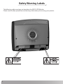
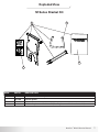
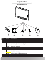
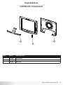
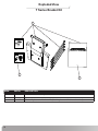
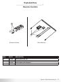
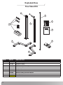
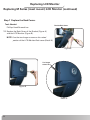
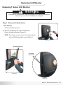
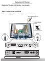
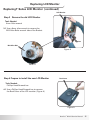
Be Strong.™
Service Manual
NV915 LCD Monitor
Model: NV915
P/N: 001-2032 Rev B ( 08/13/2007 )
Table of Contents
FCC Information.................................................... 3
Important Safety Precautions............................. 4
Product Specifications......................................... 5
Location of Safety Warning Labels...................... 6
Exploded Views and Parts Lists.......................... 7
Troubleshooting....................................................13
Replacing Headphone Jack.................................14
Replacing Keypad.................................................15
Replacing LCD Monitor (M Series Bracket)........17
Replacing LCD Monitor (T Series Bracket).........23
Important Contact Numbers...............................29
FCC Information
FCC Information
This equipment has been tested and found to comply with limits for a class B digital device, pursuant to
Part 15 of the FCC Rules. These limits are designed to provide reasonable protection against harmful
interference in a residential installation.
This equipment can generate, uses, and radiates radio frequency energy and, if not installed and used in
accordance with the instructions, may cause harmful interference to radio communications.
However, there is no guarantee that interference will not occur in a particular installation.
If this equipment does cause unacceptable interference to radio and television reception, which can be
determined by turning the equipment off and on, the user is encouraged to try to correct the
interference by one or more of the following measures.
• Reorient or relocate the receiving antenna.
• Increase the separation between the equipment and receiver.
• Connect the equipment to an outlet on a circuit different from that
to which the receiver is connected.
• Consult the dealer or an experienced Radio/TV technician for assistance.
AT T E N T I O N
• Any changes or modifications in construction of this device which are not expressly approved by the party responsible
for compliance could void the users authority to operate the equipment.
Nautilus® NV915 Service Manual
Important Safety Precautions
To reduce the risk of fire, electrical shock or
other injuries, follow these safety precautions
when installing, using and maintaining your
NV915 LCD TV Monitor.
Important!
Save these instructions
Read all instructions before using.
WA R N I N G
This symbol appearing throughout this manual means:
Pay Attention! Be Alert! Your Safety Is Involved!
WA R N I N G
• Always disconnect the power before installing or servicing the equipment.
• Disconnect the power cable and signal cable when thunder or lightning is present.
• Do not touch the power cord with wet hands. Make sure the electrical connectors are clean and dry before use.
• Disconnect the power cord when not in use for extended periods of time.
• Do not use if power cord is damaged.
• Do not install LCD Monitor close to heating sources.
• Do not place heavy articles on, or step on the LCD Monitor.
• The product should be installed in a clean and dry place.
• If you detect any smoke, unusual noise or smell, disconnect the electric power and contact service.
• Avoid contact with liquids or beverages.
• Do not use or place any combustible or flammable substances close to the LCD Monitor.
• Do not place the power cord close to any heating devices/sources.
• Do not apply any twisting forces or excess pressure to the LCD Monitor.
• Do not attempt to disassemble, repair or modify the LCD Monitor. If the LCD Monitor needs repair or adjustment, refer
servicing to qualified service personnel.
• When cleaning, do not directly spray with water or use flammable substances.
• Do not allow liquids to penetrate the LCD Monitor.
• When cleaning the LCD Monitor, disconnect the power and use a clean soft cloth. Never use a wet cloth.
AT T E N T I O N
• Any changes or modifications in construction of this device which are not expressly approved by the party responsible
for compliance could void the users authority to operate the equipment.
NV915 Product Specifications
NV915 LCD TV Monitor
Gross Weight: 12.5 lbs/ 5.7 kg
Net Weight: 9.5 lb/ 4.3 kg
Product Dimensions:49cm (L) x 17cm (W) x 43cm (H)
19.3” (L) x 6.7” (W) x 16.9” (H)
Power Requirements:
Adaptor Input: 100-240V AC, 50-60Hz
Adaptor Output” DC 12V, 3.33A
Regulatory Information:
FCC:
This device complies with Part 15 of the FCC and the Canadian ICES-003 regulations for Class A apparatus. Operations
is subject to the following two conditions:
(1). This device may not cause harmful Interferences and
(2). This device must accept any interference received, including interference
that may cause undesired operation.
The LCD TV Monitor NV915-000N Model bears the CSA Mark shown with adjacent
indicators ‘C’ and ‘US’
The LCD TV Monitor with PAL tuner bears the CE Mark and meets all safety and
EMC requirements required by the European Union and Australia / New Zealand.
For Customers in the European Union, Do not dispose of this product as refuse.
This product is to be recycled. For information on the proper method of disposal
contact a Nautilus Customer Service Representative. Contact information is available
in the Important Contact Numbers section in this manual.
The LCD TV Monitor with PAL tuner is RoHS compliant.
Nautilus® NV915 Service Manual
Safety Warning Labels
The following safety warnings are located on the NV915 LCD Monitor.
Please read all safety precautions and warning information prior to using your product.
Exploded View
M Series Bracket Kit
1
2
3
4
REF#
PART#
DESCRIPTION
1
001-1915
M Series Bracket Kit Complete
2
001-1894
Console Spacer
3
001-1959
M Series Bracket Kit Installation Manual
4
001-1944
M Series Replacement Hardware Kit (Use if replacement Hardware is needed)
Nautilus® NV915 Service Manual
Exploded View
LCD Monitor Kit
1
2
3
4
REF#
PART#
DESCRIPTION
1
001-1924
LCD Monitor with Accessories (US)
1
001-1992
LCD Monitor with Accessories (Euro)
1
001-2013
LCD Monitor with Accessories (Australia)
1
002-3782
LCD Monitor, DT with Accessories (Digital)
2
001-1922
Power Cord (US)
2
001-2015
Power Cord (Continental)
2
001-2019
Power Cord (Australia)
2
001-2017
Power Cord (UK/Ireland)
3
001-1938
Hardware Kit
4
000-8010
Power Brick
4
002-3787
002-0387
LCD, DT Power Brick (Digital)
5
001-1995
European Adapter Kit (Europe/Australia Only)
6
001-1923
Owners Manual (CD ROM)
6
001-7167
Owners Manual (Digital CD ROM)
5
6
Exploded View
LCD Monitor Components
3
1
2
REF#
PART#
DESCRIPTION
1
001-2033
Front Keypad
2
001-1945
Earphone Jack
3
001-1997
Back Cover
Nautilus® NV915 Service Manual
Exploded View
T Series Bracket Kit
1
3
2
REF#
PART#
DESCRIPTION
1
001-1948
T Series Bracket Kit Complete
2
001-1960
T Series Bracket Kit Installation Manual
3
001-1955
T Series Replacement Hardware Kit (Use if replacement Hardware is needed)
10
Exploded View
Remote Controls
1
2
Wireless Remote
REF#
PART#
DESCRIPTION
1
001-1939
Wireless Remote Kit (US)
1
001-2081
Wireless Remote Kit (International)
1
002-3785
Wireless Remote Kit (US Digital)
2
001-2028
Universal Wired Remote Kit
Wired Remote
Nautilus® NV915 Service Manual
11
Exploded View
Free Stand Kit
2
9
8
3
1
7
4
5
6
REF#
PART#
DESCRIPTION
1
001-2074
Stand Shroud Replacement Kit
2
001-1934
Upright Assembly
3
001-1851
Adjustable Mast Assembly
4
001-1935
Base Assembly
5
001-2049
Stabilizer B
6
001-2050
Stabilizer A
7
001-2036
Stand Assembly Instruction Manual
8
001-2035
Stand Hardware Kit
9
001-4874
001-2037
Stand Wire Harness
12
Troubleshooting
Poor Sound or Display Quality
• Make sure the Antenna is properly connected to the LCD Monitor, lower connection
on the unit and the video source.
• Check the Antenna Cable for damage.
No Image
• Make sure the Antenna is properly connected to the LCD Monitor, lower connection
on the unit and the Video source.
• Check the Antenna Cable for damage.
• Make sure the Power Cord is properly connected to the unit and a wall outlet.
• Press POWER button on remote.
Black Background Only
• Make sure the mode is set to TV and not PC or Video/S-Video when using a
coaxial cable input source.
Interference or Shaky Display
• Other appliances such as hair dyrers, wireless phones, power tools, etc. can cause
interferrence.
• Execute the fine tuning adjustment.
Can’t Store a Specific Channel
• Check whether Channel Setting is set to Normal.
No Sound
• Press the Mute button.
• Press the Volume Up button.
• Replace Headphone Jack
Remote Doesn’t Work
• Try the remote on another LCD Display if available.
• Make sure you have fresh batteries.
• Check or replace the Headphone Jack on the front of the LCD Monitor.
Nautilus® NV915 Service Manual
13
Replacing Headphone Jack
Over time the Headphone Jack may become worn and fail to function properly.
Replacing Headphone Jack
Tools Needed:
Phillips Head Screwdriver
Parts Needed:
Headphone Jack Kit Part# 001-1945
1. Remove the Decal covering the Headphone Jack. (Figure A)
2. Use a Phillps Head Screwdriver to remove the two screws securing the jack (Figure B).
3. Carefully remove the Headphone Jack from the LCD Monitor (Figure C) and disconnect the
wires (Figure D).
4. Reverse the procedure to install the jack.
Figure A
Figure B
Figure D
14
Figure C
Replacing Keypad
Over time the Keypad may become worn and fail to function properly.
Replacing Keypad
Tools Needed:
Phillips Head Screwdriver
Parts Needed:
Keypad Part# 001-2033
1. Remove the Back Cover of the LCD Monitor (Figure A).
2. Carefully pull the Ribbon Cable out of the connector (Figure B & C).
3. Gently lay the LCD on it’s back and peel off the old Keypad (Figure D).
4. Remove the old Keypad from the slot it the plastic (Figure E).
(Continued on next page)
Ribbon Cable
Figure A
Ribbon Cable
Figure B
Figure C
Keypad
Figure D
Figure E
Nautilus® NV915 Service Manual
15
Replacing Keypad
Replacing Keypad (Continued)
5. Insert the new Keypad ribbon cable through the slot with the adhesive side toward
the bottom of the LCD (Figure F).
6. Peel off the Adhesive Backing (Figure G).
7. Position the Keypad on the plastic and firmly press into place (Figure H & I).
8. Turn the LCD over and insert the Ribbon Cable into the connector (Figure J).
9. Replace the Back Cover (Figure K).
Adhesive Side
Figure F
Figure G
Figure H
Figure J
16
Figure K
Figure I
Replacing LCD Monitor
Replacing M Series (mast mount) LCD Monitor
7! 2 . ) . '
To avoid the risk of electrocution, shock or mechanical injury, before performing this
maintenance, ensure that the LCD Monitor is unplugged.
Step 1 Remove the Back Covers
$!.'%2
Tools Needed:
Phillips Head Screwdriver
1-1 Remove the Back Cover of the LCD Monitor
(Figure A) and the Bracket (Figure B).
!4 4 % . 4 ) / .
NOTE: Two longer screws used on the raised
portion of the LCD Monitor Back cover
(Detail A).
Figure A
Bracket Back Cover
)--%$)!4%!#4)/.2%15)2%$
Longer screws
used here
#!54)/.
Figure B
Detail A
Nautilus® NV915 Service Manual
17
Replacing LCD Monitor
Replacing M Series (mast mount) LCD Monitor (continued)
Step 2 Disconnect Wires From Monitor
2-1 Disconnect the Power, Antenna and Remote (if using optional wired remote)
wires from the LCD Monitor.
Optional Wired Remote wires.
NOTE: International
version will have
Coaxial Connection
Adapter.
International Coaxial Adapters
Power
Antenna
Power
Antenna
Antenna
Connections are REVERSED for the NV915 LCD Digital Monitor.
18
Power
Replacing LCD Monitor
Replacing M Series (mast mount) LCD Monitor (continued)
LCD Monitor
Bracket
M10 Allen Bolt
Step 3 Remove the LCD Monitor
Tools Needed:
6mm Allen wrench
3-1 Use a 6mm allen wrench to remove the
M10 Allen Bolts on each side of the Bracket.
Figure A
Step 4 Prepare to install the new LCD Monitor
Back Cover
Tools Needed:
Phillips Head Screwdriver
4-1 Use a Phillips Head Screwdriver to remove
the Back Cover of the LCD monitor. (Figure A)
Figure A
Nautilus® NV915 Service Manual
19
Replacing LCD Monitor
Replacing M Series (mast mount) LCD Monitor (continued)
LCD Monitor
Bracket
Step 5 Attach the LCD Monitor
Tools Needed:
6mm Allen wrench
5-1 Position the LCD Monitor on the Bracket (Figure A)
with the Metal Tabs resting between the upright
prongs (Detail A).
5-2 Re-Install the M10 Allen Bolts and Lock Washers.
Figure A
5-3 Position the LCD Monitor (Figure B & C).
Metal Tab
Note: The Monitor has a 30º range of viewing angles.
Position at your discretion (Figure B & C).
Prong
5-4 Completely tighten the M10 Allen Bolts.
30º Range
Detail A
30º Range
Figure B
Figure C
20
Replacing LCD Monitor
Replacing M Series (mast mount) LCD Monitor (continued)
Step 6 Connect Wires to Monitor
The connections shown are for Pre Wired units with Coaxial and power connections only.
For alternative configurations please refer to the LCD Monitor owners manual.
IMPORTANT! You must wire tie the Power Wire to the LCD Bracket to avoid
accidental disconnection.
NOTE: If you are using the optional Wired Remote, attach the end
labeled LCD TV at this time. Refer to Wired Remote Installation
Manual for more information.
NOTE: International version
will require supplied
Coaxial Connection
Adapter.
International Coaxial Adapters
Power
Antenna
Power
Antenna
These connections are not used in this configuration
For alternative configurations please refer to the LCD Monitor owners manual.
Antenna
Power
Connections are REVERSED for the NV915 LCD Digital Monitor.
Nautilus® NV915 Service Manual
21
Replacing LCD Monitor
Replacing M Series (mast mount) LCD Monitor (continued)
Step 7 Replace the Back Covers
Tools Needed:
Phillips Head Screwdriver
Bracket Back Cover
7-1 Replace the Back Cover of the Bracket (Figure A)
and the LCD Monitor (Figure B).
NOTE: Use the two longer screws on the raised
portion of the LCD Monitor Back cover (Detail A).
Figure A
Use longer
screws here
Figure B
Detail A
22
Replacing LCD Monitor
Replacing T Series LCD Monitor
7! 2 . ) . '
To avoid the risk of electrocution, shock or mechanical injury, before performing this
maintenance, ensure that the LCD Monitor is unplugged.
Step 1 Remove the Back Covers
Tools Needed:
Phillips Head Screwdriver
$!.'%2
1-1 Remove the Back Cover of the LCD Monitor
(Figure A) and the Bracket (Figure B).
NOTE: Two longer screws used on the raised portion
of the LCD Monitor Back cover (Detail A).
!4 4 % . 4 ) / .
Figure A
Bracket Back Cover
)--%$)!4%!#4)/.2%15)2%$
Use longer
screws here
#!54)/.
Figure B
Detail A
Nautilus® NV915 Service Manual
23
Replacing LCD Monitor
Replacing T Series LCD Monitor (continued)
Step 2 Disconnect Wires From Monitor
2-1 Disconnect the Power, Antenna and Remote (if using optional wired remote)
wires from the LCD Monitor.
Optional Wired Remote wires.
NOTE: International
version will have
Coaxial Connection
Adapter.
International Coaxial Adapters
Power
Antenna
Power
Antenna
Antenna
Connections are REVERSED for the NV915 LCD Digital Monitor.
24
Power
Replacing LCD Monitor
Replacing T Series LCD Monitor (continued)
LCD Monitor
Step 3 Remove the old LCD Monitor
Tools Needed:
6mm Allen wrench
3-1 Use a 6mm allen wrench to remove the
M10 Allen Bolts on each side of the Bracket.
Bracket
M10 Allen Bolt
Figure A
Detail A
Step 4 Prepare to install the new LCD Monitor
Back Cover
Tools Needed:
Phillips Head Screwdriver
4-1 Use a Phillips Head Screwdriver to remove
the Back Cover of the LCD monitor. (Figure A)
Figure A
Nautilus® NV915 Service Manual
25
Replacing LCD Monitor
Replacing T Series LCD Monitor (continued)
Step 5 Attach the LCD Monitor
LCD Monitor
Tools Needed:
6mm Allen wrench
5-1 Position the LCD Monitor on the Bracket (Figure A)
with the Metal Tabs resting between the upright
prongs (Detail A).
5-2 Re-Install the M10 Allen Bolts and Lock washers.
5-3 Position the LCD Monitor (Figure B & C).
Note: The Monitor has a 30º range of viewing
Bracket
angles. Position at your discretion
(Figure B & C).
Figure A
5-4 Completely tighten the M10 Allen Bolts.
Prong
Metal Tab
30º Range
30º Range
Detail A
Figure B
26
Figure C
Replacing LCD Monitor
Replacing M Series (mast mount) LCD Monitor (continued)
Step 6 Connect Wires to Monitor
The connections shown are for Pre Wired units with Coaxial and power connections only.
For alternative configurations please refer to the LCD Monitor owners manual.
IMPORTANT! You must wire tie the Power Wire to the LCD Bracket to avoid
accidental disconnection.
NOTE: If you are using the optional Wired Remote, attach the end
labeled LCD TV at this time. Refer to Wired Remote Installation
Manual for more information.
NOTE: International version
will require supplied
Coaxial Connection
Adapter.
International Coaxial Adapters
Power
Antenna
Power
Antenna
These connections are not used in this configuration
For alternative configurations please refer to the LCD Monitor owners manual.
Antenna
Power
Connections are REVERSED for the NV915 LCD Digital Monitor.
Nautilus® NV915 Service Manual
27
Replacing LCD Monitor
Replacing T Series LCD Monitor (continued)
Bracket Back Cover
Step 7 Replace the Back Covers
Tools Needed:
Phillips Head Screwdriver
7-1 Replace the Back Cover of the Bracket (Figure A)
and the LCD Monitor (Figure B).
NOTE: Use the two longer screws on the raised
portion of the LCD Monitor Back cover (Detail A).
Figure A
Use longer
screws here
Figure B
Detail A
28
Important Contact Numbers
If you need assistance, please have both the serial number of your machine and the date of purchase available when you
contact the appropriate Nautilus office listed below.
OFFICES IN THE UNITED STATES:
INTERNATIONAL OFFICES:
E-mail: [email protected]
For technical assistance and a list of distributors in your area,
please call or fax one of the following numbers.
• TECHNICAL/CUSTOMER SERVICE
Nautilus, Inc.
World Headquarters
16400 SE Nautilus Drive
Vancouver, Washington, USA 98683
Phone: 800-NAUTILUS (800-628-8458)
Fax: 877-686-6466
• CORPORATE HEADQUARTERS
Nautilus, Inc.
World Headquarters
16400 SE Nautilus Drive
Vancouver, Washington, USA 98683
Phone: 800-NAUTILUS (800-628-8458)
• INTERNATIONAL CUSTOMER SERVICE:
Nautilus International S.A.
Rue Jean Prouvé 6
1762 Givisiez / Switzerland
Tel: + 41-26-460-77-77
Fax: + 41-26-460-77-70
Email: [email protected]
INTERNATIONAL OFFICES:
• SWITZERLAND OFFICE
Nautilus Switzerland S.A.
Tel: + 41-26-460-77-66
Fax: + 41-26-460-77-60
• GERMANY and AUSTRIA OFFICE
Nautilus GmbH
Tel: +49-2204-610-27
Fax: +49-2204-628-90
• ITALY OFFICE
Nautilus Italy s.r.l.
Tel: +39-031-51-10-86
Fax: +39-031-34-24-97
• UNITED KINGDOM OFFICE
Nautilus UK Ltd.
Tel: +44-1908-267-345
Fax: +44-1908-267-346
• CHINA OFFICE
Nautilus Representative Office
Tel: +86-21-523-707-00
Fax: +86-21-523-707-09
Nautilus® NV915 Service Manual
29
Be Strong.™
For more information about the NV915 LCD Monitor or other Nautilus ® equipment , visit www.nautilusinc.com.
© 2007 Nautilus, Inc. All rights reserved. Nautilus, the Nautilus logo, and Be Strong are either registered trademarks or trademarks of Nautilus, Inc.
All other marks are either registered trademarks or trademarks of their respective companies.
Nautilus, Inc. World Headquarters, 16400 SE Nautilus Drive, Vancouver, Washington, USA 98683, 1-800-628-8458, www.Nautilus.com .