1
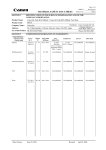
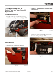
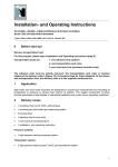
MAINTENANCE
Recommended Maintenance Schedule
Maintenance
Service Interval
Maintenance Procedure
8 hrs
•
•
•
•
•
25 hrs
• Check hydraulic oil5
• Inspect hydraulic lines for leaks
50 hrs
• Clean the foam pre-filter with liquid soap and warm water
• Clean the paper air filter by lightly tapping on flat surface
100 hrs
•
•
•
•
•
Change engine oil1, 2
Replace paper air filter1
Check battery electrolyte level
Adjust track tension
Check battery cable connections
200 hrs
•
•
•
•
•
Check hydraulic filter1, 3, 4
Check spark plugs
Replace drive belt
Replace fuel filter
Change engine oil filter
400 hrs
• Inspect fuel lines for leaks
• Change hydraulic oil and filter1
Yearly Storage
•
•
•
•
•
•
•
Grease the traction unit
Check engine oil level
Check for loose fasteners
Inspect the tracks for damage or wear
Change hydraulic filter after the initial 8-10 operating hours
Check for loose fasteners
Touch up chipped paint
Adjust track tension
Check tracks and road wheels
Complete all yearly maintenance procedures specified in the engine operator’s manual
Charge the battery and disconnect the cables (storage only)
Drain the gasoline (storage only)
More often in dusty, dirty conditions
Change oil after the first 50 operating hours
3
Change the hydraulic filter after the first 8 - 10 operating hours
4
For severe duty or rental applications, change every 200 operating hours
5
Check the hydraulic fluid level before using the traction unit for the first time
1
2
Important:
Refer to your engine operator’s manual for additional maintenance procedures.
Note: After 50 hours and then every 100 hours therafter (that is at 150, 250, 350, etc.) the screen displays CHG
OIL to remind you to change the engine oil. After every 100 hours, the screen displays SVC to remind you
to perform the other maintenance procedures based on a 100, 200, or 400 hour schedule. These reminders
come on starting three hours prior to the service interval time and flash at regular intervals for six hours.
Dingo TX420, TX425 Series Service Manual
Rev. 000
3-1
MAINTENANCE
Greasing the Traction Unit
(4) are located on the right side (Fig. 0002).
Grease all pivot joints every 8 operating hours and
immediately after every washing.
Grease Type: Lithium based NLGI2
1. Lower the loader arm and stop the engine. Remove
the key from the ignition switch.
2. Clean the grease fittings with a rag.
3. Connect grease gun to each fitting and pump grease
into the fittings until grease begins to ooze out of the
bearings (approximately 3 pumps).
4. Wipe any excess grease.
There are 12 grease fittings on the TX420/425:
(4) are located on the left side (Fig. 0001).
Fig 0002
IMG-6883a
(4) are located in the front on the quick attachment
assembly and the front loader arm assembly (Fig. 0003).
Fig 0001
IMG-6881a
3-2
Rev. 000
Fig 0003
IMG-6882a
Dingo TX420, TX425 Series Service Manual
MAINTENANCE
Maintaining the Road Wheels
4. Ensure that the road wheel turns smoothly on the
bearing. If it does not turn smoothly or spin freely,
replace the bearing; refer to Road Wheel Bearing
Replacement, page 8-108.
1. If the inner wheels or the complete tray of wheels
needs maintenance, remove the tracks. Refer to
“Track Removal” as follows:
• TX420 page 8-4
• TX425 (with a cast drive wheel) page 8-13
• TX425 (with drive sprocket wheel) page 8-29
5. Check the grease under the cap and around the
gasket. If it is dirty, gritty, or depleted, clean out all of
the grease, replace the gasket, and fill the head of
the cap with new grease (Fig. 0006).
2. Remove the snap ring from a road wheel (Fig.
0004).
Fig 0004
Note: It is not always necessary to remove the
track guide when replacing any of the road
wheel bearings. They can also be removed
by raising the unit off the ground. For safety
reasons, make sure the frame of the unit is
supported.
DSC-0821a
3. Remove the wheel bearing cap with seal (Fig. 0005).
Fig 0005
Dingo TX420, TX425 Series Service Manual
Fig 0006
DSC-0835a
DSC-0822
Rev. 000
3-3
MAINTENANCE
Hydraulic Reservoir Tank
5. Remove the cap from the filler neck and check the
fluid level on the dipstick (Fig. 0008).
Location
The hydraulic reservoir tank is located in the front of the
TX420/TX425 unit.
Hydraulic Tank Capacity: 10 gallons (37.85 liters)
Type of Oil to Use: 10W-30 detergent, diesel engine oil
(API service CH-4 or higher)
Checking the Hydraulic Fluid
Check the hydraulic fluid level before the engine is first
started and after every 25 operating hours.
1. Remove the attachment, if one is installed.
2. Park the traction unit on a level surface, lower the
loader arm, and fully retract the tilt cylinder.
3. Stop the engine, remove the key, and and allow the
engine to cool.
4. Clean the area around the filler neck of the hydraulic
tank (Fig. 0007).
3-4
Fig 0007
Fig 0008
PICT-5528
6. The fluid level should be between the marks on the
dipstick. If the level is low, add enough fluid to raise
it to the proper level.
7. Install the cap on the filler neck.
IMG-6890
Rev. 000
Dingo TX420, TX425 Series Service Manual
MAINTENANCE
Replacing the Hydraulic Filter
(TX420/425 250000401 & up Fig. 0010)
Change the hydraulic filter:
• After the first 8 operating hours.
• After every 200 operating hours.
1. Position the traction unit on a level surface.
2. Lower the loader arm, stop the engine, and remove
the key.
3. Open the hood.
IMPORTANT: Do not substitute an automotive oil
filter or severe hydraulic system damage may result.
4. Remove the old filter (TX420/425 250000399 &
lower Fig. 0009).
Fig 0010
IMG-6886a
5. Wipe the surface of the filter adapter gasket area
clean.
6. Pre-fill the hydraulic oil filter with oil and apply a thin
coat of oil to the rubber gasket on the replacement
filter.
7. Install the replacement hydraulic filter onto the filter
adapter. Hand tighten it clockwise until the rubber
gasket contacts the filter adapter, then tighten the
filter an additional 3/4 turn.
8. Wipe up any spilled fluid.
Fig 0009
IMG-6900a
9. Start the engine, raise and lower the loader arm,
then drive the unit forward and backward to purge
air from the system and check for leaks.
10. Stop the engine, check the fluid level in the hydraulic
tank (refer to “Checking the Hydraulic Fluid”, page
3-4) and add fluid to raise the level to the mark on
the dipstick. Do not over fill the tank.
11. Close the hood.
Note: Dispose of used oil and filters at a certified
recycling center.
Dingo TX420, TX425 Series Service Manual
Rev. 000
3-5
MAINTENANCE
Changing the Hydraulic Fluid
6. Remove the hydraulic tank cap and dipstick (Fig.
0012 and Fig. 0013).
Change the hydraulic fluid every 400 operating hours or
yearly.
Note: The hydraulic filter should be replaced whenever the hydraulic oil is changed.
1. Position the traction unit on a level surface.
2. Raise the loader arm, install the cylinder lock, stop
the engine, and remove the key.
3. Open the hood.
4. Allow the traction unit to cool completely.
5. Place a large drain pan (capable of holding a minimum of 11 gallons) under the drain plug on the front
of the traction unit, behind the front counterweight
(Fig. 0011).
Fig 0012
IMG-6890
Fig 0013
PICT-5528
3-6
Fig 0011
IMG-7023
Rev. 000
Dingo TX420, TX425 Series Service Manual
MAINTENANCE
7. Remove the drain plug and allow the oil to drain into
the pan.
8. When oil is finished draining, install and tighten the
drain plug.
Note: Dispose of the used oil at a certified recycling
center.
9. Fill the hydraulic tank with approximately 10 gallons
(37.8 liters) of 10w-30 or 15W-40 detergent, diesel
engine oil (API service CH-4 or higher).
10. Replace the hydraulic filter. Refer to “Replacing the
Hydraulic Filter” on page 3-5.
Checking the Hydraulic Lines
After every 100 operating hours, check the hydraulic
lines and hoses for leaks, loose fittings, kinked lines,
loose mounting supports, wear, and weather or chemical
deterioration. Replace all moving hydraulic hoses every
1500 hours or 2 years, whichever comes first. Make
necessary repairs before operating.
Vents - Hydraulic Tank
The vent location depends on the serial number of the
TX.
11. Start the engine, remove the cylinder lock, raise and
lower the loader arm, then drive the unit forward and
backward to purge air from the system and check for
leaks.
Note: The only maintenance to perform on these is
to make sure they are clean and free of any
debris.
12. Stop the engine.
240000299 & lower, the vent is in front of the hydrostat
pumps attached to the engine baffle (Fig. 0015).
13. Check the hydraulic fluid level and top it off if
necessary.
14. Replace the hydraulic tank cap and dipstick (Fig.
0014).
Fig 0014
Dingo TX420, TX425 Series Service Manual
Fig 0015
IMG-7048
IMG-6890
Rev. 000
3-7
MAINTENANCE
240000301 & up, the vent is located in front of the
engine secured to the oil cooler frame (Fig. 0016).
Oil Drain (behind the left track) (Fig. 0018)
Fig 0016
Fig 0018
A
Engine Servicing
Oil Dipstick - check oil level daily (Fig. 0017).
B
D
C
Fig 0019
A. Oil fill
B. Spark plug
3-8
Fig 0017
IMG-6899
IMG-7056
IMG-6895
C. Oil filter
D. Fuel filter
IMG-6901
Rev. 000
Dingo TX420, TX425 Series Service Manual
MAINTENANCE
• Change oil after the first 50 hrs then every 100 hrs1, 2
Fuse Block
• Oil Filter 200 hrs1, 3
Fuses are located under the hood, mounted to the tower
assembly (Fig. 0021).
• Fuel Filter 200 hrs1
• Inspect Spark Plug 200 hrs (Gap 0.030” (0.76mm))
More often in dusty, dirty conditions.
Change oil after the first 50 operating hours.
3
For severe duty or rental applications, change every
3
100 operating hours.
1
2
Refer the Kohler or Toro Operator manuals for additional
information.
ABCD
Air Filter
Every 25 hrs check and clean pre-filter and check the
paper element for damage (Fig. 0020).*
A.
B.
C.
D.
Fig 0021
IMG-6972
15 amp = Fan motor
10 amp = Neutral switch and gauges
25 amp = Charge and fuel solenoid
30 amp = Start circuit
Fuses can be removed to check continuity. The test
meter should read less than 1 ohm.
Fig 0020
IMG-6897
• Replace Paper Element 100 hrs*
* More often in dusty, dirty conditions
Dingo TX420, TX425 Series Service Manual
Rev. 000
3-9
MAINTENANCE
Belt, Hydrostatic Pumps
Track Inspection
Every 25 hours inspect the drive belt for wear or
damage.
Clean the track and drive assembly daily.
Check the track surface daily for cracks and tears.
Every 200 hours replace the drive belt.
Replace the belt if you find any signs of wear, cracks, or
damage or after 200 operating hours, whichever comes
first (Fig. 0022).
Replace the track if it is torn or cut and/or the tread is
worn (Fig. 000).
Check the center lugs daily for gouging and excessive
wear (Fig. 000).
Track Adjustment 2 3/4” (7cm) (Fig. 0023).
1. = 2-3/4 inches
(7cm)
Fig 0022
A
IMG-6889
B
Fig 0023
A. Tension nut
track install #3
B. Tensioner arm
Use an alignment tool (Toro p/n: 110-0069) to align the
track guide to drive wheel prior to track installation or if
the track lugs show wear. Refer to “Track Guide Alignment” as follows:
• TX420 page 8-112
• TX425 page 8-114
Replace the track if most of the center lugs are gouged
or worn 1/2” (1.27cm) on either side or a combination of
both sides. Nominal lug width is 2 1/2” (6.35cm) at the
base of the lug. Refer to “Track Installation” as follows:
• TX420 page 8-12
• TX425 (cast drive wheel) page 8-19
• TX425 (drive sprocket wheel) page 8-49
3-10
Rev. 000
Dingo TX420, TX425 Series Service Manual
MAINTENANCE
Battery Maintenance
Track Tread (Fig. 0024)
Batteries are available in two basic versions; maintenance free and maintenance type.
With either type of battery it is important to have clean
terminals and tight cable connections to the battery
posts. Escaping gases from the battery causes corrosion
at the terminals and other metal parts. The battery
should be cleaned periodically using a baking soda and
water mix; a couple of tablespoons baking soda to a pint
of water.
Fig 0024
PICT-3377
A maintenance type battery needs fluid level checks on
a routine basis. Use distilled water to bring the battery
cells to the correct level. Check and clean electrical connections and the changing system if the battery requires
water frequently and corrosion becomes excessive; both
are signs of over-charging.
A maintenance free battery is sealed and fluid can not be
added.
Center Lug (Fig. 0025)
Cold cranking amps (CCA) is a measurement of the
number of amps a battery can deliver at 0° F (-17° C)
for 30 seconds and not drop below 7.2 volts. So a high
CCA battery rating is good, especially in cold weather.
Sulfation of batteries starts when specific gravity falls
below 1.225 or voltage measures less than 12.4 (12v
Battery). Sulfation hardens the battery plates reducing
and eventually destroying the ability of the battery to
store a charge.
Fig 0025
Dingo TX420, TX425 Series Service Manual
PICT-3378
Rev. 000
3-11
MAINTENANCE
Sulfation is a normal process that slowly occurs over
time and is the reason a battery eventually needs replacement. However, a battery that is allowed to become
discharged and is left in this state will suffer permanent
sulfation damage and require premature replacement.
Occasional charging of the battery during storage is
recommended to the keep the specific gravity to recommended levels. This will minimize the sulfation of the
battery plates.
State of Charge
Specific Gravity
Voltage
12V
100%
1.265
12.7
75%
1.225
12.4
50%
1.190
12.2
25%
1.155
12.0
Discharged
1.120
11.9
Special Tools
Listed below are the special tools used in some of the
procedures in this manual. To order these tools, contact
the Toro Company.
Track Alignment Tool (Fig. 0026) - Toro P/N: 110-0069
For tool use example see page 8-113.
Testing
You must first have the battery fully charged prior to
any test. The surface charge must be removed before
testing. To remove surface charge the battery must
experience a load of 20 amps for 3 plus minutes.
Battery specific gravity can be measured by using a
hydrometer or a refractometer.
Fig 0026
PICT-4139a
Wheel Puller Kit (Fig. 0027) - Toro P/N: 112-2557
For tool use example see page 8-68.
Load test removes amps from a battery much like starting an engine would. The battery may have a label with
the amp load for testing and/or a CCA Cold Cranking
Amp rating. The load test number is 1/2 of the CCA
rating. For example, a 500 CCA battery would load test
at 250 amps for 15 seconds. A load test can only be
performed if the battery is near or at full charge.
If you have a maintenance free battery, the only ways to
test are with a voltmeter and/or a load test.
The reading on the digital voltmeter should be the
voltage shown in the previous table. If you have voltage
readings in the 10.5 volts range on a charged battery,
that indicates a shorted cell.
Batteries that are used in equipment that are stored for
some portion of the year can discharge and sulfation
between the battery plates can occur and shorten the life
of the battery.
3-12
Rev. 000
Fig 0027
PICT-4143a
Dingo TX420, TX425 Series Service Manual
MAINTENANCE
Spring Removal Tool (Fig. 0028) - Toro P/N: 92-5771
For tool use example see page 8-1.
Fig 0028
Dingo TX420, TX425 Series Service Manual
PICT-4131a
Rev. 000
3-13
MAINTENANCE
THIS PAGE INTENTIONALLY LEFT BLANK.
3-14
Rev. 000
Dingo TX420, TX425 Series Service Manual