1
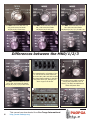
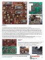
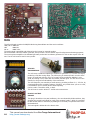
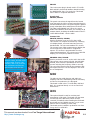
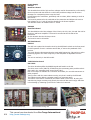
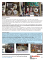
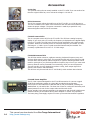
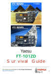
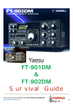
Yaesu
FT-101ZD
Survival Guide
This manual was downloaded from Fox Tango International
http://www.foxtango.org
PAØPGA
1
FT-101Z MK0
2
This manual was downloaded from Fox Tango International
http://www.foxtango.org
PAØPGA
Yaesu FT-101Z/ZD series transceiver
Yaesu FT-101ZD page
Presented by:
Fox Tango International
and PAØPGA
The FT-101 history
The Yaesu FT-101 series transceivers, produced in 1970-1978 were a very good alternative for the very expensive
American made receivers and transmitters of the time.
They were full of useful options, for which you had to pay much $$$ extra (if available) in other ham equipment.
Build like a battleship, with a modular construction, it was easy to repair, and the big numbers which are still around,
prove the sound work of the Yaesu engineers at the time.
The FT-101 series was very successful, and there were many versions of it, starting with the FT-101, released in 1970 to
the FT-101F, who was released in 1978. See the FT-101 page for more information for the FT-101 series of transceivers.
The Yaesu FT-101ZD was brought on the market in 1979, as a low-cost alternative for the FT-901ZD, which is the real
descendant of Yaesu’s famous FT-101 series of transceivers.
As Yaesu already had a very good reputation for performance and durability, it is no wonder that the new series
transceivers became very popular in the ham community, special in Europe, because the high $$$ price of the available
American equipment and the high import taxes on them, and the fact that there where almost no agents prohibited a
broad distribution of American equipment. I still think the American industry at the time missed a chance here.
Only Heathkit had a representative over here, and was very popular at the time for their nice kits.
Yaesu had a small sales network in Europe and the Swiss firm Sommerkamp imported the same sets with other
typenumbers and under the name Sommerkamp, they were a big success in Italy and Germany.
This manual was downloaded from Fox Tango International
http://www.foxtango.org
PAØPGA
3
MK3
The FT-101Z/ZD
In 1979 Yaesu announced a new version of the FT-101, called the FT-101Z (analog dial) and ZD, (with digital dial).
The FT-101ZD looked very much like the FT-901, but had a simpler internal construction with just a couple of plug-in boards
for HF, premixer and oscillator. The IF and the audio board, were connected with plugs from a wire harnass, the power supply
boards are soldered direct to the wire harnass, thus not the overall modular construction that made the older FT-101 and
new FT-901 so popular.
Altough the construction of the FT-101ZD was simpler, the transceiver was packed with useful features, that appealed to
many hams, (including myself, I bought one in 1979, and still use it almost daily,).
It had a very sensitive receiver, SSB and CW modes, a digital display, very liniair VFO, smooth tuning, a good set of filters, a
PA with real transmitting tubes (6146B’s), speech processor, IF shift with passbands between 300hz and 2.4khz, a clarifier,
a calibrator and a noise blanker, making it a very complete package for a very reasonable price. Later models had also AF
notch/peak filters, WARC bands and AM/FM capability. There were outputs for connection to a transverter and liniar amplifier,
inputs for a second VFO and phone patch. It was one of the best buys you could made at the time.
The FT-901 had even more bells & whistles, but had also a $ 1000 higher pricetag.
The transceiver is very well build, with good quality components, and, if used normally, will last forever. Weight is in excess
of 15 kg, due the built-in power supply, giving it the feel of a battleship.
The powersupply can be fed from 100/110/117 or 200/220/235 Volts 50/60hz, and with the optional switching unit, even
from 13.8 Vdc, altough you need a heavy-duty car battery. (current in voice peaks around 20 Amps).
Analog model FT-101Z
4
FT-101ZD MK1
This manual was downloaded from Fox Tango International
http://www.foxtango.org
PAØPGA
Specifications FT-101Z, FT-101ZD:
Type:
Frequency Range:
Mode:
RF Power output:
Sensitivity:
Selectivity:
Image rejection:
Display
Power:
Current drain DC:
Impedance:
Dimensions
Weight:
Manufactured:
Accessoires:
Amateur HF transceiver
10-160m,
SSB/CW,
SSB/CW
AM
SSB/CW:
AM:
SSB/AM
CW
FT-101Z
FT-101ZD
Mains,
Receive:
Transmit:
50 – 75 ohms,
15 kilograms
1979 – 1982
FV-101Z
FV-101DM
FL-2100Z
SP-901P
FC-901
(early models had no WARC bands)
(later models also AM or FM)
100W
35W
0.25 uV (10db S/n)
0.5 uV (10db S/n)
2.4 khz @ -6db,
4 khz @ -60db
600 or 300 hz, (optional)
- 60 db (160-15m)
- 50 db (10m)
analog dial
analog + digital dial
100-235 V ac 50/60hz
5.5 Amps,
13.8 Vdc option
1.1 Amps with heater off)
Max. 21 Amps.
SO-239 connector
345 * 157 * 326 mm (W*H*D)
external VFO
external scanning VFO
Linear Amplifier 1200W SSB, 1000W CW
External Speaker/Phone Patch
Antenna Coupler
The FT-101ZD is updated several times during its lifetime, and there are in fact 4 different types, using the same designator.
By the introduction in 1979, the transceiver had only SSB and CW, later there was a AM (tx/rx) option, still later the Warc
bands were introduced, and the last version had it all, including a optional AM or FM board, and Audio notch/peak filter.
The later models have more features, so they are more in demand, and are normally higher priced in auctions or on the
internet. It seems difficult to see what the difference is between the first and last models because there is not much changed
on the front.
Fortunately there is a easy way to see at a glance the difference between the various models, the only thing you need to
know is the serial number of the set.
The Yaesu serial number on the back of the set consists of a number, a letter and 6 numbers:
The first number is the year of production:
The letter is the production month:
The next 2 numbers are the production run:
The next 4 numbers are the serial numbers:
9=1979, 0=1980, 1=1981 a.s.o.
C=jan D=febE=march a.s.o.
from 01 (first series) to 24 and higher (last series)
from 0001 to 9999
TIP
Identification of the model is easy by the use of the production run:
FT-101Z/ZD MK0
Production run:
160-10m, SSB/CW, only, WWV rx-only, aux
01 – 07, all in 1979
FT-101Z/ZD MK1
Production run:
160-10m, SSB/CW/AM, WWV rx-only, aux
Only Run 16 has the new type counter.
08 – 16
FT-101Z/ZD MK2
Production run:
160-10m + WARC, SSB/CW/AM
17 – 23
FT-101Z/ZD MK3
Production run:
24 – 30? up
160-10m + WARC, SSB/CW/AM or FM
The last serie is also easely identified by the grey and silver knobs on the front.
This manual was downloaded from Fox Tango International
http://www.foxtango.org
PAØPGA
5
The MK0 model has SSB and CW
only, and covers the bands
160,80,40,20,15 and 10m.
The MK1 model has SSB, CW and
AM , and covers the bands
160,80,40,20,15 and 10m.
The MK2 model has SSB, CW and
AM and covers the bands
160,80,40,30,20,17,15,12 and 10m.
Differences between the MK0/1/2/3
The MK3 model has SSB, CW and
AM or FM and covers the bands
160,80,40,30,20,17,15,12 and 10m.
6
The switchboard in all models of the
FT-101ZD has the same functions,
but in the MK0, MK1 and MK2 models
they have black tumblers, in the Mk3
they have silver tips, fitting by the
silver rings on the knobs.
This manual was downloaded from Fox Tango International
http://www.foxtango.org
All models have a width control for
varying the passband of the IF
filter(s), the MK3 has additional a
audio APF/Notch filter.
PAØPGA
The Bandswitch of the MK0 and MK1 have 11 positions for the standard amateurs bands 160, 80, 40, 20, 15, 10m, a
receive only position for 5 - 5.500 Mhz, and a position for a optional band. The MK2 and MK3 bandswitch has 12
positions for the 160, 80, 40, 30, 20, 17, 15, 12 and 10M bands, so including the WARC bands.
The Preselector and the Plate tuning have in the MK0 and MK1 positions for the “old” hambands, in the MK2 and MK3
they have also positions for the WARC bands, resulting in a more cluttered arrangement.
All three models have a clarifier, wich allows tuning of +/- 5 khz around the original frequency, just enough for splitfrequency DX work, or for round-table QSO’s, if one of the members is not spot-on the frequency. The clarifier can be
used in receive or transmit mode, or both. In the MK3 model ( here on the right) there is also a Squelch knob for use
with the optional FM board.
Optional CW Filter
In the FT-101ZD, a CW filter is an option, and can easely be installed
on the IF board. The normal filter has a bandwith of 600 hz. Later
there was also a filter of 300hz, but using this filter, there is a
serious loss of signal, both on receive and transmit, because the
smaller bandwith.
The FT-101Z story
The FT-101Z was the budget version of the FT-101ZD, with a nice and
surprisingly exact mechanical dial instead of a digital dial, but otherwise
both models are the same in every way.
The FT-101Z was delivered in all the versions, from MK0 to MK3.
The digital counter module was an option and update is easy if you can find
one because all wiring is available in every transceiver. Just plug it in.
For all models with a serial number under 159999 you need the early type
counter module with TTL IC’s, above 16000 the newer counter with LSI chip.
This manual was downloaded from Fox Tango International
http://www.foxtango.org
PAØPGA
7
The various models and the used boards
FT-101ZD MK0
FT-101ZD MK1
FT-101ZD MK2
FT-101ZD MK3
Sn#
01 – 07xxxx
08 – 16xxxx
17 – 23xxxx
24 – upxxxx
RF board
NB/Fix
Premix
IF
AF
Premix LO
Sel.switch
VFO
Rect A
Rect B
Capacitor
Trimmer A
Trimmer B
Trimmer C
Bandwidth
APF
Driver
Final
Clarifier
LED
Lever switch
Display
Decoder
Counter
AM (**)
FM (**)
PB1960A
PB1961B
PB1962A
PB1963B
PB1964A
PB1965
PB1966C
PB1440B-3420
PB1967
PB1968A
PB1969A
PB1970
PB1970
PB1092
PB1972
PB1714A
PB1715A
PB1973A
PB1974A
PB1975A
PB1978
PB1979
PB1980
-
PB1960A
PB1961B
PB1962A
PB1963C
PB1964A
PB1965
PB1966C
PB1440B-3420
PB1967
PB1968A
PB1969A
PB1970
PB1970
PB1092
PB1972
PB1714A
PB1715A
PB1973A
PB1974A
PB1975A
PB1978 (*)
PB1979 (*)
PB1980 (*)
PB2040
-
PB2154
PB1961B
PB2152
PB1963C
PB1964A
PB2153
PB1966C
PB1440B-3420
PB1967
PB1968A
PB1969A
PB1970
PB1970
PB1092
PB1972
PB1714A
PB1715A
PB1973A
PB1974A
PB1975A
PB2098A
PB2086A
PB2040
-
PB2154
PB1961B
PB2152
PB1963C
PB1964A
PB2153
PB1966C
PB1440B-3420
PB1967
PB1968A
PB1969A
PB2193B
PB2192B
PB1092
PB2217
PB1714A
PB1715A
PB1973A
PB1974A
PB1975A
PB2098A
PB2086A
PB2040
PB2218
(*)
(**)
only production numbers starting 16xxxx had the PB2086A counter
optional, the AM board, or the FM board can be installed (MK3 only).
The used boards in detail:
RF boards
PB1960A and PB2154A
Contains the RF pre-amplifier, the receiver and transmitter mixer and a buffer stage,
The mixer output of 8.9875Mhz goes to the IF board. The in and output tuning of the
RF amplifier is done by permeability-tuned circuits, resulting in high sensitivity and
excellent rejection of unwanted out-of-band signals.
PB-9060A RF board component side
PB-9060A RF board solder side
8
The difference between the two boards is the mixer. The PB1960A uses a balanced
mixer with 2 Fet’s, the later PB2154A board uses a diode ring mixer, for a better big
signal behavior.
PB-2154A RF board component side
This manual was downloaded from Fox Tango International
http://www.foxtango.org
PAØPGA
IF board
PB1963B/C
The IF board is the heart of the transceiver, and is the same in every type of FT-101ZD.
The signal is first passed trough a monolithic filter with a bandwith of 10 khz, to have a wide band point for noise
blanking. The signal pass then the noise blanker gate and is fed trough the SSB filter or the optional CW filter to the IF
first mixer. Here the incoming signal is heterodyned with a 19.7475 Mhz local signal. This local signal is delivered from a
XCO and the resulting mixing frequency is 10.76 Mhz. This 10.76 Mhz signal is fed trough a second SSB filter, and mixes
with the same 19.7475 Mhz local signal back to the original IF frequency of 8.9875 Mhz. The 19.7475 Mhz XCO is tuned
with a varicap over a close range, and the result is that the passband of the first and second filter shifts along each other,
so in effect making the passband smaller or broader, depending of the frequency of the XCO. It is a very useful item, you
can make the band pass as low as 300 hz, and as high as the original passband of the first filter. (SSB 2.4 khz, CW 300 or
600 hz). The skirt of the filters add, so the filter passband improves too.
The output from the second IF mixer is fed to a 2-stage IF amplifier, and is delivered to the AF unit.
On the board are also a AGC amplifier and S-meter amplifier, the SSB tx IF filtering and the speech processor with filter.
The board has the SSB filter installed, and there is room for installing a 300 or 600 hz CW filter.
NB-Fix unit
PB1961
This board is also used in every FT-101ZD, and contains the noise blanker
circuitry and a x-tal oscillator for 2 fixed frequencies. The fixed
frequencies are sideband dependent, so the operating frequency is on
LSB 3 khz higher than on USB at a given x-tal frequency.
The necessary x-tals have to be in the VFO (5 – 5.5 Mhz) range.
This manual was downloaded from Fox Tango International
http://www.foxtango.org
PAØPGA
9
AF Unit
PB1964
The AF unit board contains the SSB/CW diode ring demodulator and the carrier oscillator:
USB, CW rx 8989 khz
LSB
8986 khz
CW tx
8988.3 Khz
The audio signal is amplified and delivered to the internal or external speaker.
On the AF board is also the marker generator, who provides a 25 khz marker signal for alignment and testing purposes.
The tx microphone amplifier with sideband generator, and a 800 hz sidetone generator for CW are also a part of the AF
unit. The AF unit board is used in every model.
VFO Unit
PB1440B-3420
The VFO uses a modified Collpitts type oscillator to generate a 5 –5.5 Mhz VFO signal,
producing a 500 khz tuning range. The VFO tuning is extremely liniair over the entire
range, no small feat with the use of a “normal” tuning condenser. Stability is very
good, and tuning is very exact with the smooth precision gear. The VFO is one of the
reasons for the good overall stability of the transceiver.
The VFO frequency can varied by a small amount, providing a offset of +/- 2.5 Khz, by
a varicap diode and a controlling voltage. (Clarifier), very useful when you are in a net,
if all members are not exactly at the same frequency.
Can be used in TX and Rx mode, or both.
This VFO unit is used in all the FT-101ZD series transceivers.
Premix Local Unit
PB1965
This plug-in board has 10 crystal oscillators, who are selected by diode switches, they
generate the premix local signal for each of the amateur bands + WWV. It is possible
to add another band on the board, by adding the neccessary components and rewire
the bandswitch.
The local signal is delivered to the Premix Unit.
10
This manual was downloaded from Fox Tango International
http://www.foxtango.org
PAØPGA
PB2153
This is the newer plug-in board, used in FT-101ZD
MK2 and MK3, that has all amateur bands including
the WARC bands 30m, 17m, and 12m. This board
has no WWV or a optional AUX band.
Premix Unit
PB1962, PB2152
The premix unit mixes the signal from the Premix
Local Unit with the VFO or crystal controlled signal in
a double balanced mixer. The premix signal is passed
trough a bandpass filter and delivered to the RF Unit.
The older board PB1962 has 7 filters, the newer
WARC board PB2152 has 9 filters, for coverage of all
amateur bands, including the WARC bands in the FT101ZD MK2 and MK3. See the table.
TIP
The MSM-9520RS was produced
solely for Yaesu, and was never
on the market. There is a kit
available, with a PIC processor,
wich substitutes all functions.
See the page 19 or the site:
http://homepage3.nifty.com/
RadioGaGa/COUNTER_e/
Counter Unit
PB1978, PB1979, PB1980,
Used in production runs 01 to 15 in the 101ZD
This counter is a complete enclosed unit, consisting
of a display board, a counter board and a count/
decode board. The unit uses standard TTL circuits.
The counter has a offset programming to display the
correct frequency of the carrier in a ingenious
manner. The counter is programmable for other
offsets with dipswitches. The counter uses 6 HP LED
displays, for a frequency readout to 100 hz.
PB2086A-3420, PB2098
Used in production runs 16- to the end in the 101ZD
This counter uses a custom LSI chip, the OKI MSM9520RS, wich has all the possibilities of the older
counter including the frequency offset in one chip.
The rest of the board is used for the transistor digit
and segment drivers. The LED displays in this counter are multiplexed.
AM Unit
PB2040
The AM print has a AM detector and audio preamplifier, and at the transmitting side the necessary
circuits for the production of a AM signal.
This board is used in the FT-101ZD MK1, MK2 and
MK3. It is a optional board, so it is not used in all
transceivers.
FM Unit
PB2219
This optional board is used for receiving and
transmitting in FM mode. The board uses the same
connections as the AM board, which must be
removed (if installed) when installing the FM board.
One board can be installed at a time, so you must
make a choice. Installing is rather easy.
This board can be installed in production runs from
24 up, the FT-101ZD MK3
This manual was downloaded from Fox Tango International
http://www.foxtango.org
PAØPGA
11
Power Supply
PB1967
Rectifier A board.
This board delivers all the high and low voltages used in the transceiver, so be careful,
there are points with 900 Volts dc on this board, and that voltage can do serious
damage to a unsuspecting Ham to say the least.
Unload always the condensors, preferabely with a resistor, before starting to work at
this circuits.
The board is positioned in the underside of the transceiver and delivers the various
low voltages (6, 8, 12 Volt dc) and the 900Vdc for the Power Amplifier.
This board is used in all models of the FT-101ZD
PB1968
Rectifier B board
This board delivers the bias voltages of the PA unit, the 150, 160, 200 and 300 Vdc for
the driver and Power amplifier. This board is mounted at the left side of the
transceiver.
On this board is also the CW keyer circuit.
The board is used in all models.
APF/NOTCH unit
PB2217
The APF unit is placed in the audio circuit by the APF/Notch switch on the front panel.
For APF operation forms it a selective active filter, to narrow the passband of the
receiver.
The notch function elimenates selective some audio frequencies, like carriers or other
interfering signals. The center frequency of the APF/Notch is adjustable from the
front.
This unit is used only in the MK3 model.
12BY7A Driver board
PB-1714A
The driver board amplifies the SSB/CW signal and feeds it to the PA.
The driver uses a tube (12BY7A) for delivering the neccessary power, and the tube is
also used in the automatic level control circuit (ALC).
Part of the output is available at a connector at the back, for use with transverters or
other purposes.
Tuning is done with the same inductive tuning unit, that is used by the RF board.
The inductive tuning allows a constant output over a greater range.
The heater of the tube is switched by the heater switch on the front. By using this
switch during longer receiving-only periods, the tube will last much longer, and there
is less heating up. Warming up time for the tubes is 60 seconds.
The trimmer boards (MK0/1/2)
12
The inductive tuning unit
This manual was downloaded from Fox Tango International
http://www.foxtango.org
The Driver board position
PAØPGA
The Power Amplifier
PB-1715A
The Power Amplifier, consists of two 6146B heavy duty transmitting tubes, the input filter and the output filter.
The output filter delivers the RF signal to a suitable antenna. The impedance from the antenna has to be between 50 and
75 ohms unbalanced. A Antenna with a different impedance at the feedpoint can be used, but there must be a matching
device between the transceiver and this feedpoint. The same goes for other antennas with a lower impedance such as
magnetic loops and others.
The 6146B PA tubes are very rugged, and can deliver around 100 -120 Watts output depending on the band of operation,
by a input of 180W in the SSB and CW mode. In AM mode the maximum input power is 45 Watt. This is due the fact that
the SSB signal has just one sideband, which has only 25% of the power factor of a AM signal, so the tubes can deliver in
SSB 4x the power of a AM signal, at the same dissipation.
It is never a good idea to push the PA to the limit, it is much better to run the PA with powers around 150W input in SSB/
CW, the tubes will last much longer, and the difference at the receiving station is minimal. You will be surprised how many
DX stations can be worked with low power. It all depends on an effective antenna, band conditions and operating skill,
and not only big power: you have to double your power output to make a S-point difference at the receiving station!
6146 series tubes:
There are several different types of 6146 tubes, and, now tubes are getting scarce is it good to know what possibilities
there are for replacing the tubes with others. The FT-101ZD uses the 6146B type, which has the biggest dissipation, thus
the biggest output, but has a bad reputation for VHF oscillation and TVI as result. They must be very good neutralized,
otherwise the PA destroys itself. The basic 6146 and 6146A (same tube, with a sturdier heater) is still around in great
numbers an can be used if there are no 6146B’s available. The only drawback is the lower power capacity: the anode
dissipation is 25% lower and they need a new neutralization and a correction of the bias voltage.
Another tube is the 6146W, a military designation, used as a remplace for 6146, 6146A and 6146B in the forces. This
tube has a rugged construction, similar to the 6146B, but the saying goes that the input power on this tube should also
be reduced to ca 75% of the nominal output of the 6146B. 6146 and 6146A may be mixed, but never mix a 6146(A) with
a 6146B, because you are in for very strange effects, and some fireworks.
There are other tube designations, they are put together in a small table at one of the next pages.
This manual was downloaded from Fox Tango International
http://www.foxtango.org
PAØPGA
13
Accessories:
Cooler Fan
The optional cooling fan can easely installed on the FT-101ZD. If you use another fan
than the original Yaesu fan, see to it that the voltage is 110 Volt ac.
DC-DC Converter
The DC-Dc converter allows the mobile use of the FT-101ZD, on a 13.8 Vdc source.
The unit is installed on the back of the transceiver and uses the internal transformer to
obtain the proper voltages. The power connection is made by a special DC cord,
delivered together with the DC-DC converter.
FV-101Z external VFO
This is a compact remote VFO for the FT-101ZD. The VFO has a analog frequency
display. If you use it with a FT-101ZD, the frequency is displayed on the digital display
from the FT-101ZD. The VFO has a precision tuning mechanism with a silky-smooth
operation. Clarifier for transmit,receive or transceive frequency is included. The VFO
shift range is +/- 8khz. Up to 6 crystal-controlled channels may be installed. The
necessary crystals have to be in the 5 - 5.5 Mhz range.
FV-101DM external VFO
This VFO has twelve memories, up/down scanning, keyboard frequency entry and
receiver offset tuning in 10hz steps. This provides smooth and precise tuning for SSB
and CW. Either the keyboard, main tuning knob or up/down scanning buttons can be
used for quick QSY to you preferred operation frequency. Up to four of you most used
memory channels can be protected from overwriting, when you store frequencies.
The two-loop PLL circuit is designed to produce a crisp, clean output signal for a
spurious-free receiver and transmitter.
This VFO can only be used with the FT-101ZD MK3, serial numbers above 240001
FL2100Z Linear Amplifier
The FL-2100 is special designed for the FT-101ZD transceiver. It uses two rugged
572B/T160 transmitting triodes in a class AB2 grounded grid configuration.
Power input is 1200 watts PEP on SSB and 1KW on CW, on all bands, including the
WARC bands 10, 18 and 24 Mhz. The linear has 2 fans for cooling the final tubes, and
special protection circuits for the output tubes and the tank circuit.
During standby is the antenne switched to the transceiver and the built-in SWR meter
allows monitoring of the feedline during either amplifier or exciter-only operation.
The heavy-duty powersupply requires no warm-up time and has excellent regulation.
14
This manual was downloaded from Fox Tango International
http://www.foxtango.org
PAØPGA
FT-901DM accessoires on the FT-101ZD
The FT-101ZD can use accessories of the FT-901DM, but there are some
restrictions at their use.
FV-901DM external VFO
This is a external VFO that provide a synthesized control system for your FT-101ZD. It
has a 3-speed scanner, which will take you instantly everywhere in the band, and the
auto-scan feature sweeps the band until it finds a signal. The synthesizer has a
steprate of 100 hz and is coupled to a 40-memory bank for storing the frequency. Fine
tune is done with the TX/RX clarifier.
Because there is no frequency display on the FV-901DM, use of this VFO in
combination with the analog FT-101Z is not possible, as the operating frequency
cannot determined.
FTV-901R transverter
The FTV-901R is a 3-band VHF/UHF transverter, all in one compact case. The basic
FTV-901R comes equipped for 144 – 148 Mhz. 6 meter and 70 centimeter modules
may be added.
The satellite 1-3 bands provide operation on OSCAR modes A/B/J on full duplex, when
a external receiver is used. Repeater split is provided on 6 and 2 meters.
YO-901 Multicscope
The YO-901 Multiscope provides superb monitoring capability, with a instant interface
to the FT-101ZD and can be used to monitor the output signal with trapezoidal and
two-tone tests, general oscilloscope measurements are also possible. A panoramic
adapter is a available option for a quick band activity examination. IF rx and tx
monitoring is not possible with the FT-101ZD combination.
SP-901P speaker/hybrid phone patch
The SP-901P features a shaped-response loudspeaker and a hybrid phone patch,
allowing efficient operation during patches. Styling and size match the FT-101ZD and
FT-901DM series.
FC-901 Antenne coupler
The FC-901 antenna coupler presents a 50 ohm load to your FT-101ZD transceiver, all
across the band. 3 coax-fed and one random-wire antenna may be accomodated.
SWR and Power metering allow quick determination of proper matching conditions.
This manual was downloaded from Fox Tango International
http://www.foxtango.org
PAØPGA
15
A Internet buy
The PA with 6146A and 6146B tube
The “skilfully repaired” PA
The creative relay solution and choke
Recently I buyed a FT-101Z on the Internet for a reasonable price, intended
more or less as spare for my FT-101ZD, that I own for almost 26 years now,
obtained new in 1979, one of the first production runs. The normal asking
price overhere is around 350 Euro’s, depending on condition. The price at 175
Euro (around $200) was good. The distance to the owner was under 100 Km,
making collecting possible. That way I could see what I got, (it is not the first
time that the pictures used by the auction have nothing to do with the actual
set). Well, the set was also a early version from 1979, so in view of spares for
my own transceiver it was ok. It looked nice enough, some scratches on the
top and sides, but a nice front. After removing the cover, I saw that the cover
of the PA was missing and that the neutralizing condenser was not connected.
The receiver worked ok, I could test that with the griddipper that I always take
with me for this purpose. The Ham was using it for the reception of weather
cards at the time, but had buyed a transceiver with a general coverage receiver,
for a better coverage. The FT-101Z had of course a analog display, and was
with the optional CW filter. The overall sight of the interior was very nice, and
at first sight I saw no modifications. The original crystals were there for all
amateurbands, the first thing to look for, because many sets are converted to
11 metres and have had a life of hard labour. Only the PA was a mess, it had
been repaired, but in a very crummy way, so I had to restore it back to the
original form. Some wires were half molten and the original wiring was changed.
I could not test the set on the air or at a dummy, because the seller had only a
piece of wire as antenne. The tubes were glowing, so I took the set at home.
After some cleaning and inspecting, there were no further surprises, only a
rewired mike connector, and some scratchy switches and potmeters. The
components, including power supply condensers and solder joints were OK.
However, when I pulled the PA tubes, I saw to my surprise that they had put in
a 6146A along a 6146B tube, one of the most serious mistakes you can make
with this tubes. You have to have 2x 6146(A), or 2x 6146B, and preferabely a
matched pair for optimal use. The input relay was changed in a very crude way,
glued to the chassis with a blob of silicone and the output lowpass filter was
removed. I have all wiring redone with 0.8mm silvered wire, isolated with the
original oil tubing, repaired the coil connections, rewired the neutalizing parts
and the output power meter. A new coil for the output lowpass filter was made
from 1.2mm silvered wire and I put in a new antenna relay with 16A silver
contacts. I think the PA looks a lot better now.
I have used a couple of 6146A tubes in this set, because they are at hand, and
to test the possibility for using that kind of tubes in this PA. They work fine.
The power output is not important for me, 100 Watts does everything I need,
and the output tubes will last forever. In my first FT-101ZD I have still the
original General Electric 6146B final tubes, and they look and work as new.
Wim PAØPGA
The PA now, after reconstruction
6146 type tubes and equivalents:
TIP
6146
25W = 6293 (heavy duty pulse tube, 5-10x longer lasting)
6146A
25W = 8298
6883A/8032 (12V heater)
6146B
35W = 8298A
YL1370
6883B/8032A (12V heater)
YL1372 (12V heater)
6146W
35W = 6146W
(fabricated as 6146B after 1962)
QE-06/40 25W = 6146A
European version by Philips & Mullard
QE-06/40F = 12V heater, K = 13.8 V heater, H = 26V heater
The rebuilt PA with 6146A tubes
16
This manual was downloaded from Fox Tango International
http://www.foxtango.org
PAØPGA
The 6146 Family of Tubes
by
Glen E. Zook, K9STH
Probably the most used tube of all times in the final amplifier of “boat anchor”
transmitters is the 6146. From the early 1950s until at least the 1980s, the 6146
found its way into virtually every manufacturer’s line of transmitters. In fact, during
the early 1960s RCA had a series of advertisements on the back cover of QST that
listed a different manufacturer’s equipment that used the 6146 each month.
There are actually three distinctive variants of the basic 6146: The 6146, 6146A, and
6146B. It is unfortunate that the 6146B was called the 6146B for it is really a different
tube from the first two. Primarily the difference between the “plain” 6146 and the
6146A is the makeup of the heater (“filament”). The 6146A has what RCA calls the
“dark heater”. This “dark heater” is supposed to be more resilient to vibration, work
well at a larger “range” of voltage, etc. Otherwise, the 6146 and the 6146A are the
same tube.
In mid-1964 RCA introduced the 6146B with the “claim” of 33.33 percent higher
power input than the 6146 / 6146A. Also, it was “claimed” that the 6146B could be
directly substituted for the earlier tubes. The 6146 / 6146A had a maximum rated
power input of 90 watts for CW and SSB operation and the 6146B had a rating of 120
watts for the same emissions.
Many amateurs are aware that the military “ruggedized” version was designated the 6146W (I will get to these tubes a bit later).
However, RCA also introduced in the early 1960s the 8298 tube for use in commercial mobile equipment. The 8298 is just a “heftier”
6146A. Motorola, General Electric, and quite a number of other commercial FM equipment manufacturers used these tubes in all sorts
of FM communications equipment for both low band (30-50 MHz) and high band (150.8 - 172 MHz). When the 6146B was introduced,
RCA “announced” the 8298A commercial equivalent of the 6146B. In fact, most of the RCA 6146B tubes were “cross branded” with the
8298A number in addition to the 6146B.
Those companies who were manufacturing 6146 series tubes for the military changed from the “plain” 6146 to the 6146A to the
6146B as the military decreed. However, all of the tubes manufactured under military contracts were known as 6146W and, to my
knowledge, nothing was done towards marking the tubes as being equivalents of the 6146, 6146A, or 6146B. The only way of telling is
from the “date code” which is printed on each tube. Different manufacturers changed tube types at different times. Also, I know of no
“master list” telling on what date a particular manufacturer changed from the 6146 to the 6146A to the 6146B. The only “sure” way to
know if a particular 6146W is of either the 6146 or 6146A type is to look for a “code date” of before 1964 since RCA introduced the
6146B in the middle of that year. However, some manufacturers did not start manufacturing 6146B equivalent 6146W tubes for at
least a year after RCA introduced the 6146B.
RCA “claimed” that the 6146B was directly interchangeable with the earlier members of the 6146 family. Unfortunately, this did not
hold true in most cases. Collins, Heath, and probably other companies, at first issued various documents saying that the use of the
6146B in their equipment was “fine”. But, this soon proved otherwise!
For example, when the 6146B was used in the Collins 32S-1, 32S-2, 32S-3, 32S-3A, KWM-2, and KWM-2A it was discovered that the
components in the neutralization circuitry “burned up” in a very short amount of time. Thus, Collins had to retract the statement that
it was “OK” to use the 6146B. Then, due to the fact that the United States military establishment wanted to “standardize” on the
6146W equivalent of the 6146B, the neutralization components had to be redesigned to allow the 6146B to be used. Fortunately, these
changes did not affect the use of the earlier 6146 and 6146A in those transmitters manufactured to use the 6146B. All three types of
tubes may be used without any problem in these transmitters.
Replacing the 6146 / 6146A tubes with 6146B types often results in spurious emissions, parasitic oscillations, etc. This is due to the
fact that there are different bias requirements, different inter-electrode capacitances, etc. of the 6146B versus the other two. It is
often difficult to neutralize 6146B tubes when used in place of the 6146 / 6146A. If neutralization can be achieved, often it lasts for
just a few minutes before the tube(s) goes into oscillation.
If one insists on trying the 6146B tubes in place of the 6146 / 6146A types, the very first thing to do is to neutralize the final amplifier.
If it will not neutralize, then the 6146B tubes should immediately be replaced with the older type tubes. If it does neutralize, then the
neutralization should be “watched” for several hours (even days) of operation. If the neutralization changes, then the 6146B tubes
again should be replaced with the 6146 / 6146A series. If the neutralization remains constant after several days, then use of the
6146B is fine in that particular transmitter.
This manual was downloaded from Fox Tango International
http://www.foxtango.org
PAØPGA
17
I have, in my shack, a number of transmitters that use the 6146 / 6146A type of tubes. These include Collins 32S-1, 32S-3 (earlier
model before the neutralization was changed); Heath Apache, DX-100, DX-35, SB-401, SB-110, Seneca; Johnson Pacemaker; and other
transmitters as well. Every one of these is much “happier” with the 6146 / 6146A family of tubes. In addition, I have owned
transmitters like the Knight T-150 and T-150A that use the 6146 tubes. Frankly, these transmitters were much happier with the 6146 /
6146A tubes.
There is another 6146 family tube that is “superior” for operation at least through 10 meters. That is the 6293. This tube was designed
for “pulse” service and is rated at 1-Kilowatt pulse power input. The primary difference between these and the “normal” 6146 is that
the plate is much “heavier” in its construction. Back in the late 1950s and early 1960s we would almost “kill” to get our hands on a pair
of these for our DX-100s, etc. The 6293 outlasts the 6146 in “normal” service by at least 5 times and often more than 10 times the life
of the tube. These tubes “show up” at hamfests, swap meets, etc., from time-to-time. If you see some of these, definitely “glomp” onto
them!
The 12-volt equivalent of the 6146 is the 6883, the equivalent of the 6146A is the 6883A, and the 6146B is the 6883B. Now, there are
the tubes that were manufactured for FM commercial service. These series go as follows: 6883, 6883A / 8032, 6883B / 8032A / 8552.
Again most of these are “cross branded” with all of the tube numbers that are equivalent.
From 1970 until late 1979 when Motorola went out of the reconditioned equipment business, I owned the Motorola reconditioned
equipment center for the south-central United States. We reconditioned Motorola FM equipment for 14 states, everything that Motorola
sold reconditioned that was exported, and everything that was sold to the United States Government (this was the height of Viet Nam
and the Government did buy reconditioned equipment!).
At that time, the Motrac series of mobile equipment was very popular. Depending on the model, these normally used one, or two, of the
6883A / 8032 tubes. It was only in the very “latest” models (HHT “E” series, LHT series, and MHT series) that Motorola had redesigned
the equipment to use the 6883B / 8032A / 8552 tubes. Around late 1976 or early 1977, Motorola decided to eliminate some of the tube
types that they were “stocking” at the Schamburg, Illinois, parts depot. Thus, they started shipping 8552 tubes in boxes that were
marked as 8032. The Motrac is unique in the fact that you cannot see the tubes when they are in operation (they are enclosed in a
metal “heat sink”). In fact, it is difficult to even “tune” a Motrac when the heat sink is not in place.
We went through from 50 to over 100 of the 8032 type tubes per week and within days were “down” to using the 8552 tubes in the
8032 boxes. Within a very few days of starting to use the 8552 tubes we started receiving complaints that virtually every Motrac unit
that was received by customers arrived with one, or both, tubes broken. Prior to this we had never had a single complaint. Upon
investigation we found that the 8552 tubes had so many parasitic oscillations that they were getting so hot that the glass envelope was
being annealed! This was happening within a minute, or two, of tune-up and final quality control. When the radio was subjected to
normal vibrations of shipping, the glass envelope of the tubes was being shattered.
This was reported to Motorola. At first they refused to believe us saying that we must have gotten a “bad” shipment of tubes. But,
within a couple of weeks they received over 1000 complaints from their service stations about exactly the same problem. It cost
Motorola one “heck of a lot” of money to pay the warranty claims because they had tried to “cut costs” by eliminating the earlier type of
tube. They had to re-box all of the 8552 tubes that had been put into 8032 boxes and get in a “rush” shipment of 8032 tubes.
The whole problem stemmed from the fact that the “B” series of tubes is not the same as the “plain” and “A” series. The parasitic
oscillations were caused by the different bias requirements and by the “fixed” neutralization of the driver and/or amplifier tube in the
Motrac. There was no practical way to change the circuitry to handle the “B” series tubes. Also, making such a change would void the
“type acceptance” of the units.
In a “practical” sense, it is “OK” to mix 6146 and 6146A tubes since the primary difference is in the design of the heaters. But, NEVER
mix 6146 / 6146A tubes with a 6146B! This is really “asking for trouble”.
Also, in a number of transmitters and transceivers (especially the Heath SB-Line) the heaters (“filaments”) of the pair of 6146 tubes are
in series. In these units it is very easy to change the heaters from series to parallel and substitute the 6883 / 6883A / 8032 tubes. The
12-volt equivalent tubes are often available for “pennies” because of the vast number that were used in the commercial FM market. I
have done this with my Heath SB-110A and it works “like a champ”. If you every want to change back, it is a very simple operation to
do so.
I know that there are amateurs who say that they have used the 6146B tubes in place of the 6146 / 6146A without any problems. I can
definitely believe that. But, I have seen way too many examples of the 6146B causing problems in relation to the cases in which the
substitution has no effect. As I said before, neutralize and keep checking the neutralization for several days if you do replace your 6146
/ 6146A tubes with 6146B types. Otherwise, you can find yourself with TVI, “burned out tubes”, and other damage to your transmitter.
You must be VERY careful when dealing with the various tubes of the 6146 family, otherwise you just might be in for some very
interesting problems. Substitute if you must, but, be aware that you are “treading on thin ice”.
Copyright article: Glen E. Zook K9STH, reprinted with his permission, tnx Glen!
More interesting articles on his website: http://home.comcast.net/~k9sth/
18
This manual was downloaded from Fox Tango International
http://www.foxtango.org
PAØPGA
Removing the Yaesu WARC bands TX disabling modification on FT101 ZD MKII.
( N.B. The Yaesu Mod did not disable the RX for the WARC bands)
The Driver mod works by effectively adding extra capacitance from the lower bands
across the coil, so that the WARC bands cannot tune to the required frequency, and no
drive is therefore produced for the PA.
This Mod removes the extra capacitance and
the WARC bands can then tune correctly. There are no adjustments to make after the
wiring change.
Takes about 15 minutes and you get three bands Going
PREPARATION
a. Turn the FT101ZD over with the front panel towards you. The Driver section is on
your Left hand-side half way up.
a. Remove the Driver section metal plate. Two of the lid securing screws will be hidden
under some foam.
c. The S1E wafer is next to the PA section, which is at the Left hand side rear. The S1D
wafer is in front of this one towards the front on the unit.
S1E wafer
S1D wafer
d. Identify the 3 BLUE wires and a GREY wire all joined together on a spare hole at the
top of the S1E wafer. The Blue wires are connected to the S1D wafer.
1
S1E wafer
S1D wafer
3 BLUE Wires
a GREY Wire
The MODIFICATION
1. Cut all the wires off the communing point on switch wafer S1E, 3 blue & 1 Grey wire.
Cut all the wires.
position 40 metre
30 metre
17 metre 12 metre
2. Remove completely the grey wire to switch wafer S1D position 12 metre.( best done
by using long nosed pliers and twisting it off )
3. Remove completely blue wire off switch wafer S1D position 40 metre.
17 metre
30 metre
2
4. Connect as a loop Blue wire on switch wafer S1D position 30 metre to switch wafer
S1D position 20 metre.
5. Connect as a loop Blue wire on switch wafer S1D position 17 metre to switch wafer
S1D position 15 metre.
17 metre connected to 15 metre as a loop
30 metre connected to 20 metre as a loop
6. End of modification.
foam tape
Driver section metal plate placed
Mario Chomicz (G8ODE) & Teruhiko Hayashi (JA2SVZ)
3
Counter Replacement Module
Text and explanations by Teruhiko Hayashi ( JA2SVZ ) http://homepage3.nifty.com/RadioGaGa/COUNTER_e/
For YAESU FT-101Z / FT-107 / Sommerkamp FT-307 / FT-707 / FT-901,902 (later version)
DISPLAY COUNTER UNIT (PB-2086A)
Custom Integrated Circuit (MSM9520RS) Replacement Module
Is your precious, beloved 101ZD still displaying the frequency?
“Pre-DSP/MPU era transceivers” from YAESU often made use of a custom
integrated circuit (IC), MSM9520RS in their DISPLAY COUNTER UNIT.
The bad news is that MSM9520RS is somewhat prone to failures. Since
this particular IC was not a standard product but a custom ordered IC by
YAESU and its production has been discontinued for long time, there is
very little hope to obtain a replacement part for repair, even at world
famous TOKYO AKIHABARA!
This replacement module takes advantages of the flexibilities of PIC
microcontroller (PIC 16F873) to “simulate” the exact functionalities of
MSM9520RS in the DISPLAY COUNTER UNIT: PB-2086A, equipped in FT101Z, FT-107, FT-707 and FT-901/902. This module restores their frequency display functionality when MSM9520RS fails.
Those YAESU models were designed and produced at the “supreme” of analogue technologies and can still perform “beautifully” when
properly maintained. (and with frequency display, of course!)
My FT-101Z came from one of my friends several years ago and like many others, the frequency display was nonfunctional:
MSM9520RS was dead. Since the entire transceiver except its frequency display was functional and in good shape, I decided to develop
this PIC replacement module for myself. It did not take too long for me to realize that many people in the world are desperately looking
for MSM9520RS and I started thinking I can be of their help.
Applicable Models
Originally this module was designed for and tested in my
YAESU FT-101Z but thanks to other enthusiastic
volunteers, the applicability of this module to other
YAESU models has been verified and tested. So far, the
following YAESU models can make use of this
replacement module.
FT-101Z
FT-107
FT-707
FT-901/902 (later version only)
For FT-901/902, the early versions did not use MSM9520RS for its frequency display; therefore the early version is not applicable. The
later version can be distinguished with its brightness control knob: “DIM” located on the left side of the frequency display. Also, the
DISPLAY COUNTER UNIT is marked as PB-2086A, with MSM9520RS 40 pin DIP IC.
Contents of the KIT
This module is offered as a parts kit form. It contains a custom made,
double sided printed circuit board for converting the 28 pin of the PIC
microcontroller to 40 pins of MSM9520RS, programmed PIC 16F873,
20.000 MHz crystal (for frequency measurement standard as well as
PIC clock generation) and resistors, capacitors and a transistor for
modifying the preamplifier circuit on the DISPLAY COUNTER UNIT:
PB-2086A.
The Assembly and Installation Manual is available for down load.
Please contact Teruhiko Hayashi (JA2SVZ) by e-mail: [email protected] for ordering information, S/H cost estimation and for
other technical information!
Prerequisite: It is necessary to unsolder 40 pin DIP IC (MSM9520RS) from the board: this may be a little challenging if you are not
familiar to. You need to deal with fine foil patterns on the conversion printed circuit board: routing between 1/10 of inch DIP IC pins.
Usually it takes a couple of hours for someone who often conducts transistor/ IC projects as a hobbyist to complete the assembly,
installation and adjustments.
This manual was downloaded from Fox Tango International
http://www.foxtango.org
PAØPGA
19
Hints and Kinks
by
PAØPGA
In this section I will give facts and thoughts, that I have collected from all over the net.
When sources are known, I will mention them, because to hold your FT-101ZD in an excellent condition is only possible
when all real amateurs, share their knowledge and experiences.
That’s still the first rule for a Ham in my opinion.
Of course are all tips free to use, but using them is always at your own risk. If you don’t have the knowledge or technical
skill, then please let the lids of your set closed, it is always better to have a good working transceiver then a perfect heap
of junk. Never try to be smarter than the HF engineers of the design Lab, there is almost always a good reason that
things are done the way it is.
Most modifications are small, and are additions for a specific reason, not a complete rebuild of the set.
So have said that, we start with a collection of tips:
First of all:
Get the proper user and service manuals for the equipment that you have, and make yourself familiar with the working of
the circuits. The manuals for the FT-101Z and ZD, and other Yaesu communication equipment are on the FoxTango site,
in PDF format, free to download, (well, a small donation is very much appreciated, to keep things rolling), so
there is no reason to start without them.
Special recommended is the very extensive Maintenance Service Manual, with around 200 pages, which is not only very
interesting, but gives all information on boards, voltages, trouble shooting lists and in general all information to keep your
FT-101ZD in a first class condition.
Switching the fan:
When the rig is mostly used on receive, there is no need to let the PA cooling fan run continuous.
I switch the fan with the heaters On/Off switch:
Pick up the 12V of the heater circuit at the accessory socket at the rear of the transceiver and rectify it with a diode and a
suitable elco. Use the DC voltage to switch a small relay. I used a small 12V reed relay with 1 contact. Use a suitable
series resistor to limit the current. With the relaycontact you can now switch one 100 Volt connection to the fan socket.
I made this modification 25 years ago, and it works still as a charm. There is room enough in the back of the transceiver
to mount the relay and the couple of small parts you need in a neat manner.
Source:
PAØPGA
Improving second Double Balanced Mixer:
On the AF board is the double balanced mixer, D02 to D05, they are 4x 1S4007.
Replace these with 4x Motorola MBD-702 diodes and the adjust VR01 and TC02 for the best carrier balance. It should be
possible to null the carrier almost completely.
Source:
G3TJP
First mixer overload
(only FT-101ZD MK2 and MK3, board PB-2154, used after run 17xxxx,)
RF board: Improve the dynamic range of the first mixer by modifying the T-Pad attenuator on the input as follows:
Change R8 (120R) to 36R, change R9 and R10 (10R) to 27R.
Reset overall gain on IF board using VR02, which is the source load of Q15.
Source:
G3TJP
Improved Fine-tuning:
Shunt the clarifier control with a 4k7 or 5k6 resistor, then recentre its action by adjusting VR01.
This mod reduces the control’s range.
Source:
G3TJP
Tips from Kiwi land
On 10 meters the transmitter takes off on HF or with the transverter beiing used. The problem is dry joints or earthing
points around the 12BY7. Resolder all connections on and around the 12BY7 board.
Source:
ZL3MH
20
This manual was downloaded from Fox Tango International
http://www.foxtango.org
PAØPGA
Fault blows main fuse every 0.5 to up to 6 hours and is not the 6146’s flashing over.
There are vertical type caps in PB-1968 and the internal fluid runs down and arc across the narrow gap in the caps (300
Volt screen supply, a common problem in TV sets).
Replace caps C1001, C1002, C1003 and C1004, they are all 10uF/450 Volts.
Source:
ZL3MH
Replace the 1000pf condensor from the plate of the driver tube to the grids of the 6146B’s.
This a precautionary measure, as the FT-101 series had problems here.
Source:
ZL3MH
The Noise Blanker stops working sometimes.
It appears to be a dry joint on plug pins of the Noise Blanker/ Fixed
channel board.
The fix is to solder around the connections of the board.
Source:
ZL3MH
I had the same type of dry joints in the cable connectors of the
audio board, and the cable connectors of the IF board, there where
several pins with craters around. See picture.
This gives all kinds of curious problems. Resoldering is the cure.
Source:
PAØPGA
The transmitter stops working:
The band change switch is in two parts. It is joined where it goes to the 6146B compartiment from a steel shaft to a fiber
shaft. This connection comes loose, and the bands do not line up properly.
It is a good precaution to mark the shafts with a markerpen and tighten the screws on the band switch extension. I heard
from a FT-101ZD repairer spending days to track this one down.
Source:
ZL3MH
FTV-250 and FTV-650B on the FT-101ZD.
The FT-101ZD is designed for the FTV-901 series of transverter via the 11-pin accessory socket.
The Plate, screen and bias voltages are not always wired to the accessory socket. This is needed if you want to run the
FTV-650B 6-meter transverter that is designed for the earlier FT-101 series.
Especially the MK3 model did not have the above wiring.
Both the FTV-250 and FTV-650B can be used with this mod on all FT-101ZD’s.
Source:
ZL3MH
Help notes on the FT101Z/FT101ZD
Collected tips from everywhere, sources unknown.
** there are several versions of the FT-101ZD, and some of these faults do not apply to all versions. **
Blowing mains input fuse :
Disconnect PA anode clips to see if one of the PA valves is short circuited. If not, then some of the diodes in the main
bridge rectifier are probably short circuited.
Intermittent blowing of mains input fuse :
If the fuse blows every now and again, then suspect that one of the PA valves is flashing over once in a while.
Fluctuations in power output :
Check the PA valves. Check the PA anode choke.
Sizzling/arcing from PA :
Check the PA anode choke.
Low power output on some bands :
Check the PA anode choke and also the coupling capacitor from the PA to the output tank circuitry.
PA unstable on higher frequency bands :
If the neutralisation is OK, then check if the 12BY7A driver is glowing blue on transmit - replace if it is.
This manual was downloaded from Fox Tango International
http://www.foxtango.org
PAØPGA
21
Low sensitivity rx :
If the marker can be received at the normal level then suspect the aerial fuse. If the marker signal is low as well then
suspect the PA driver 12BY7A - this shares a signal frequency tuned circuit with the RF stage. Q8 on the IF board also
causes this problem sometimes.
PA tuning incorrect :
If the PA won’t tune correctly on some of the bands then check for short circuits on the output tank coil and the nearby
wiring.
No rx :
Check the width control is not set at one end (surprisingly common).
No tx and no bias :
Check accessory plug is in octal socket at back. Check the PA screen grid voltage - if it is missing check D1002, D1012,
and R1006 on Rect.B unit.
No CW tx :
Check Q1003 on Rect.B unit (possibly Q1001 and Q1002 as well). I have had failure of the CW carrier osc xtal on a
couple of occasions.
No tx 28-30mhz only :
Check R8 which is mounted on the band switch assembly near the driver.
RF feedback on 21/28mhz :
Some units had a four way tag strip near the mic. i/p socket - the two centre earth connections should be connected
together.
Incorrect frequency display on one band only : Suspect the local osc xtal for that band.
Poor rx/tx on one band only : Local osc xtal as above.
11m reconversion :
These rigs were sometimes converted for illegal CB use. This usually involved replacing 28.5-30 MHz with 26.5 to 28
MHz. A few rigs are still around in this state, and will require re-converting back to 10
metres. This will require the replacement of the local oscillator crystals, and re-alignment. Realignment should not be
omitted, as the rigs may intermittently fail to operate correctly if it is. Change required local osc xtals for the original
types and the local osc must be re-aligned to ensure continued reliable operation.
Hum on rx when volume control at min :
This is usually caused by a hum loop. If there are two earth braids connected to the v/c then cut one of these.
Hum on tx :
Same as above but on mic gain control.
One segment of display does not light :
LED U/S. Note these are usually in sockets and are easily swapped for checking.
Incorrect segment illumination on one digit :
Digit driver IC U/S.
Intermittent incorrect frequency display :
If on one band only, suspect the local osc xtal on that band - check alignment of osc before ordering crystal, especially if
fault is on 10m (because it may have beiing used for illegal CB and not realigned). If on all bands suspect Q04 or Q05 in
the counter (later models) - note that Q04 must be the S version.
Intermittent rolling frequency/panel lights dim :
Suspect a dry joint on the LT smoothing cap. Also suspect the cap itself.
Lumpy VFO :
This is caused by wear of the VFO tuning mechanism. I have tried a number of times to repair and lubricate this, but
always without success, although it may last a short while.
To be continued…………………
22
This manual was downloaded from Fox Tango International
http://www.foxtango.org
PAØPGA
TIP
Buyers Beware
Be careful by buying any FT-101ZD transceiver with AM/FM and previously used on 27 Mhz by good
buddy’s, they have all been heavely overloaded by users that had no real knowledge what they are
doiing, so suspect the worst. They liked special the tube-type final sets, because they are not so easely
distroyed by misuse as the more modern sets with transistor PA’s.
When you buy such a transceiver, it will cost at least a couple of final tubes, at a additional cost of
around $ 100.-, if not the total repair of the Power Amplifier. It is better to pay something more for a
good-looking, not over-used set from a known source. The same goes for the FT-901DM, even more
popular with the CB folks because they had the AM and FM boards installed.
If the price is too good to be true, it usually is. Cheap sets are usually problem sets.
If you can repair everything yourself and have the time, there is nothing wrong with buying cheap, but
usually the sets are otherwise misused too, so you always end up with a lesser set than the one in good
condition, carefully used by a fellow ham. Of course this sets can also have some problems, but have at
least the potential to be restored to a first class piece of equipment. Use your common sense.
Always try to collect the set yourself, that way you can see what you are in for. Sometimes to meet the
vendor can give you a clue how the set was used.
Buying at Internet is a good source, if you take some precautions:
If the seller uses the internet much, he has usually a quality marking to his name, wich gives a clue to
his reliability, but this means also that he buys and sells very often, and is more interested in a quick
buck, than in the equipment itself. So please beware, and be careful. You see often the same pictures of
very nice equipment in ads, but when you receive it, is it a box full of junk, scratched and mostly with a
lot of internal problems. See the FT-901DM page for a sample.
The best buys come from local hams, or hams who want to upgrade to a newer ricebox with more menu’s and knobs to fiddle with. To obtain the new toy, they sell the old, reliable sets often for a modest
price. Another source can be the usual swapfest or estate sell fom a deceased Ham.
Of course you have to inform yourself on the market value of the set you are looking for.
Actual prices change with general condition, the available options or accessoires, and are often
negotiable. Take your time, and keep an eye at ads, sometimes you have to act fast if your dreamset is
at an auction for the right price. If you are in a hurry, you can always place a ad in the asked catagory.
6146 type power tubes:
Try to buy NOS tubes of American brands, I have a special liking for RCA tubes, but other good brands
are GE, Eimac, Tungsram, Raytheon or European Philips, Mullard, Siemens or Telefunken. All this firms
don’t make tubes anymore, but there are still much tubes on the market. Good tubes last practically
forever, if you use them properly, special the ruggidized types and SQ types in Europe.
They are in most respects much better than the Chinese and Russian and many other mysterious brands
that are on the market today.
A special warning may be worth the brands Haltron and Ultron. They were tube manufacturers in the
previous East-European countries and produced low-cost versions of all kind of popular tubes. They still
produced tubes when the other brands closed their factories. If you look close to the construction you
see skewed electrodes, balloons skewed in the sockets, and a general miss of quality. They never last as
long as the others. I prefer anytime a 50% tested secondhand RCA tube to a new Haltron.
73
PAØPGA
Keep them glowing...
This manual was downloaded from Fox Tango International
http://www.foxtango.org
PAØPGA
23