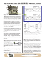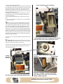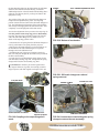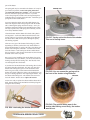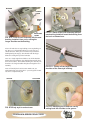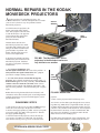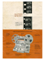
1
Repairing the
Kodak Instamatic M80
Projector
Includes the
variations in other
M-series projectors.
Plus...Normal Repairs on the
Kodak Moviedeck Projectors.
A Publication of Fargo Enterprises, Inc.
REPAIRING THE
KODAK INSTAMATIC M80 PROJECTOR
...and other models in the M-series.
Plus tips on repairing the Kodak Moviedeck projectors.
Contents
By Curt Fargo & Larry Lyells
M-SERIES
REPAIRING THE M-SERIES
PROJECTORS -----------------------------------------FLOW CHART ------------------------------------------RECOMMENDED TOOLS ---------------------------INSPECTION, REMOVING THE BOTTOM
COVER ----------------------------------------------------DISASSEMBLY -----------------------------------------CHECKING THE CAM BUSHING -----------------DISASSEMBLY OF THE MECHANISM ---------SHUTTER REPAIRS & INSTALLATION --------REPAIRS ON THE CAM-SHAFT ASSEMBLY -INSTALLING AND TIMING THE DRIVE-CAM
ASSEMBLY ----------------------------------------------REPLACING THE DAMPING ARM ---------------COMPLETING REASSEMBLY OF THE
MECHANISM --------------------------------------------REPLACING THE REWIND DRIVER -------------TESTS AND ADJUSTMENTS ----------------------FINAL STEPS OF REASSEMBLY ----------------TROUBLESHOOTING SUMMARY ---------------LUBRICATION SUMMARY -------------------------WIRING PICTORIALS ---------------------------------
1
2
3
4
6
12
12
16
21
23
25
27
31
32
36
36
37
37
M80 SPECS AND OPERATION
FROM THE KODAK MANUAL ---------------------Tools, specifications ----------------------------Operation --------------------------------------------Pulldown system --------------------------------Film selector --------------------------------------Spindle operation -------------------------------Rewind operation -------------------------------Direction of shifting operation ---------------
38
38
38
38
39
40
40
41
Courtesy Kodak.
MOVIEDECK SERIES
NORMAL REPAIRS IN THE KODAK
MOVIEDECK PROJECTORS ----------------------DISASSEMBLY STEPS ------------------------------DISASSEMBLY TO REMOVE
THE SHUTTER -----------------------------------------REMOVING AND REPLACING
THE SHUTTER ------------------------------------------
42
42
44
46
©2001 by Fargo Enterprises, Inc. All rights reserved. This publication is for information purposes only.
Fargo Enterprises, Inc. is not responsible for any damage caused to projectors while following these
procedures. Success in projector repair depends on the skill of the technician.
REPAIRING THE M-SERIES PROJECTORS
FIG. B1 The Kodak Instamatic M80 projector.
M
any repairs on the M-series of Kodak Instamatic movie
projectors are now practical. True, Kodak no longer
supplies parts—the projectors have been out of production
for too many years. But you can get many parts—including
those most frequently needed—through Fargo Enterprises,
Inc.
FIG. B2 Control panel for the M80.
Fargo Enterprises, Inc. has arranged for the frequently
needed parts to be specially manufactured or rebuilt. Also,
Fargo Enterprises, Inc. acquired the remaining supply of
parts from Kodak. If you would like a list of the parts
available, contact Fargo Enterprises, Inc. and request a copy
of the Micro-Tools catalog. Or check the parts online at
www.fargo-ent.com/kodak.htm.
For several years, Fargo Enterprises has also been repairing
the M-series projectors. We've gathered our M-series
experience for this manual. Here you'll find the instructions
for making the normal repairs to the Kodak M-series
projectors.
This manual focuses on the M80 projector. But all projectors
in the series are very similar. Where there are significant
differences, we've described the variations during the
disassembly. That way, you can follow these instructions
while you're working on any projector in the M-series.
What are the differences? Here's a list of the main variations
in the series:
M80. The first projector in the series runs both super-8 and
regular-8 film. The special super-8 adapter shown here fits
over the supply spindle,
increasing the diameter for
super-8 reels. The projector has
two lamp brightnesses and three
running speeds—54 fps, 6fps,
and NORMAL (18fps). The M80 uses the 120V projection
lamp.
M85. A less-expensive version of the M80, the M85 has
only one lamp brightness and one running speed (18fps). The
M85 also runs both super-8 and regular-8 film. The projector
uses the 120V lamp.
M70. The main differences between the M70 and the M80
FIG. B3 The two types of lamps. Note that
each lamp has one thick pin and one thin pin—
the pins are reversed in the two types.
are that the M70 runs only super-8 film and has a singleblade shutter (the M80 has a double-blade shutter). The M70
uses the 120V lamp with two lamp brightnesses.
M90. The M90 is the same projector as the M70 with one
exception—the M90 uses the 21V lamp, a variation that
requires a step-down transformer in the projector to drop the
line voltage to 21V.
M95. Here is the top-of-the line projector in the series. The
M95 has all the M-series features. Like the M90, the M95
uses a 21V lamp that requires the step-down transformer.
Another very similar projector is the Ektagraphic MFS-8, a
super-8 projector closely related to the Instamatic M-series
projectors. The MFS-8 has three running speeds, uses the
120V DNE lamp, and adds the convenience of a remote
control. There are a few internal variations among the
different projectors. You'll see these differences during the
disassembly. To see the major electrical differences, turn to
the wiring pictorials on page 37.
1/KODAK M-SERIES PROJECTORS
If you're new to the repair field, you'll need certain tools you
probably don't have. See the next section for the recommended tools. Also, there are some standard disassembly/
reassembly tips you might keep in mind:
1. You'll see this precaution over and over—but, for your
own safety, never plug in the projector with the bottom
cover removed. Unplug the projector, remove the bottom
cover, make any repairs or adjustments, replace the bottom
cover, and then plug in the projector to check operation.
2. Try to leave a large enough work area that you can spread
out the parts. Keep screws with the parts they hold. A large,
clean work area is also desirable to avoid losing parts.
Remember, the projectors have been out of production for a
long time, and not all parts are available. If you lose a part,
you may need to keep searching—it's not always possible to
buy a replacement.
3. In this manual, we'll go through reassembly as well as
disassembly. But you can always establish your own reassembly sequence—just reverse the order of your disassembly. For this reason, it helps to place the parts in order as you
remove them. In some cases, we have used slight variations
in the reassembly sequence (for the purposes of testing or to
make reassembly a little easier). But you can still simply
reverse your disassembly sequence—it's not necessary to
follow our reassembly sequence in exact order.
4. It helps to make sure you understand a part's operation
before you remove that part. If you're in doubt about some
phase of the operation, you might take a disassembly break
and check the Operation section starting on page 38. Here
we used the explanations and drawings provided in the
original the Kodak manual, a manual that's no longer
available from Kodak.
FLOW CHART
The flow chart for the M80 shows the sequence of operations—what drives what. During the discussions
of disassembly, troubleshooting, adjustments, and operation, you may wish to refer to this flow chart to
see the order of control. Only the major actions are shown.
120V
LINE POWER
LAMP
MOTOR
FAN
BELT
An arrow shows the
direction of control. A
dashed line indicates that
the two boxes are actually
one part—for example, the
up-and-down cams are
formed on the shutter-drive
shaft.
SWITCH
UP-AND-DOWN CAM
GEAR
SHUTTER-DRIVE SHAFT
FILM CLAW
IN-AND-OUT CAM
BELT
TAKE-UP SPINDLE
2/KODAK M-SERIES PROJECTORS
REWIND DRIVER
BELT
BELT
CAM SHAFT
FAST REWIND
SUPPLY SPINDLE
RECOMMENDED TOOLS
FRONT ROW, LEFT TO RIGHT: straight hemostat HEM-885-10, curved tweezer TWZ-302-28,
spring tool 51-1852.
SECOND ROW, LEFT TO RIGHT: single-edge razor blade, probe (pick) DD6, scriber with magnet
7077HS.
THIRD ROW, LEFT TO RIGHT: Starrett 6” digital caliper 721A-6-150, Wiha Phillips screwdriver
1x60mm 26110.
FOURTH ROW, LEFT TO RIGHT: cleaning brush (toothbrush) BRUSH, Wiha thin-walled 1/4” nut
driver 26563.
FIFTH ROW, LEFT TO RIGHT: heavy-duty syringe (glass and metal) DV-101 with blunt needle 182 (for grease), syringe B205-TPR (for oil), cotton-tip applicator FB100 362-P (for a quantity of 100).
BACK ROW, LEFT TO RIGHT: Pliobond adhesive 3oz bottle P-601-F, canned air (dusting gas)
1623, cleaner AK225 Asahikinlin 8oz 1663-85-F, Super Lube grease 3oz tube 21033, shutter oil
NYOIL.
There are two types of screws you encounter in the projector—one type has a standard Phillips head
and the other type has a hex head (a head with six flat sides). The Phillips screwdriver shown above
will handle all the Phillips-head screws. Use the 1/4" nut driver for the hex-head screws. Because of
the tight clearances in some cases, the thin-walled nut driver is essential. For the cleaning brush, you
can substitute a discarded toothbrush. But you don't want crossed bristles, bending heads, or the other
amenities often found in today's toothbrush—that's why we offer a simple, inexpensive toothbrush
that's great for scrubbing projector parts. The numbers and letters in italics following the item indicate
the order code.
For a complete catalog of tools, contact Fargo
Enterprises, Inc. Or check the tools online at
www.micro-tools.com/
3/KODAK M-SERIES PROJECTORS
INSPECTION, REMOVING THE BOTTOM
COVER
FRONT PLATE
I
nspection—that's the first step when you receive a
projector for repair. In a minimum amount of time, you
can determine what's wrong with the projector and what
parts you may need.
From the outside of the projector, evaluate the overall
condition. Check the damping arm, Fig. D1. There's a good
chance the plastic has become brittle with age and has
broken away, as in the illustrated projector, Fig. D2. Replacing the damping arm requires that you remove the projector
mechanism from the housing. But before you order a new
damping arm, there are a few more things to check.
To check the shutter mechanism, we'll remove the bottom
cover, Fig. D3. Caution: Be sure to unplug the projector
from the wall outlet before you remove the bottom cover.
Working on a partially disassembled projector that's connected to line voltage risks serious electrical shock.
1. Take out the four 1/4" drive screws located within the
cavities at bottom of the projector, Fig. D3.
2. Some projectors have an additional two Phillips screws
located near the handle. Remove these screws also, Fig. D3.
3. Lift aside the bottom cover as shown in Fig. D7.
4. The power cord in the bottom cover still connects to the
projector. To completely remove the bottom cover, first twist
off the wire tie, Fig. D7, to separate two of the wires.
5. The other lead of the power cord connects to the switch,
Fig. D6. Note the position of the power-cord lead. The
power-cord lead connects to the port labeled "L." But the "L"
port may be in the lower right-hand corner as in Fig. D6 or in
UPPER BOTTOMCOVER SCREWS
FIG. D1 Front view of the M80 projector.
DAMPING ARM
FIG. D2 A broken damping arm.
the upper left-hand corner. Insert your curved tweezers next
to the power-cord lead as shown in Fig. D6. Then pull the
power-cord lead out of the switch port.
VARIATIONS: If you're working on an M90 or an M95,
note the differences in Fig. D8 and Fig. D9. The M90 and
M95 use the 21V projection lamp rather than the 120V
projection lamp. Projectors that use the 21V lamp have a
large step-down transformer, Fig. D9, to drop the line
voltage. Also note the difference in the switch position, Fig.
D8—the "L" port for the power-cord lead is in the upper lefthand corner.
The bottom cover is now completely disconnected from the
projector. Set aside the bottom cover while you examine the
projector mechanism.
BOTTOM-COVER SCREWS
FIG. D3 Bottom of the M80 projector. Not all
projectors have the two upper screws. Note
that the bottom cover stores the take-up reel.
4/KODAK M-SERIES PROJECTORS
If the projector won't advance the film, the most likely
problem is a damaged shutter gear. Look in the area shown
by the dashed circle, Fig. D7. Fig. D4 and Fig. D5 show
enlargements of this area. In Fig. D4, the shutter gear has
been chewed away—the gear teeth are completely missing.
In Fig. D5, the entire gear is missing—the gear has broken,
and the sections may be inside the projector.
SHUTTER GEAR
IP: Before getting too far into the projector, check the
plastic guide—the guide is black plastic in Fig. D7 and
white plastic in Fig. D9. If the guide is cracked or broken,
there's no use proceeding with the disassembly—you can't
get the guide as a replacement part. If the projector belongs
to a customer, return it as unrepairable. If you own the
projector, you can use it for parts or as a practice mechanism.
Or perhaps you can locate an unrepairable projector you can
use for parts.
T
SWITCH
PORT IDENTIFICATION
FIG. D4 This projector has a broken shutter
gear—a new shutter is needed.
HUB FOR SHUTTER GEAR
FIG. D5 Here
the shutter
gear has
completely
broken away.
FIG. D6 Unplug the lead of
the power cord from the
switch.
SWITCH
GUIDE
WIRE TIE
FIG. D7 Bottom cover lifted aside.
MOTOR
5/KODAK M-SERIES PROJECTORS
FORWARD/REVERSE ARM
GUIDE
SHORT
SPRING
FIG. D8 Variation—the switch
position is slightly different in the
M90 and M95 projectors. The L port
is in the upper left-hand corner.
FIG. D9 Variation—the M90 and
M95 projectors use a transformer
to drop the line voltage for the 21V
lamp.
DISASSEMBLY
TRANSFORMER
With either a broken shutter gear or a broken damping arm,
it's necessary to remove the mechanism from the projector
housing. You'll see the other normal repairs as we proceed.
But remember that you'll occasionally encounter the repair
you can't perform—simply because the projector is so old
that parts are no longer available.
MOTOR
6/KODAK M-SERIES PROJECTORS
FAN HOUSING
C
BAFFLE
Use your canned air (duster) to blow out the dirt from the
inside of the projector. Keep the canned air handy. You'll
probably be using it throughout the disassembly to clean out
the projector.
1. Lift out the loose grille, Fig. D10.
2. Bow in the paper baffle, Fig. D10, until the slot at its top
edge disconnects. Lift out the paper baffle to uncover the
motor, Fig. D9.
3. Go now to the front of the projector and lift the top cover
as shown in Fig. D1. Snap off the front plate, Fig. D1.
Spring tabs hold the front plate to the projector.
4. Still at the front of the projector, remove the lamp, Fig.
D11—just push down the wire clip and unplug the lamp.
5. Pull forward the pressure-plate tension arm as shown by
the arrow in Fig. D12; then lift up the pressure-plate tension
arm to lock it in place. Lift out the pressure plate, Fig. D12.
6. Push down the film-path cover plate as indicated by the
arrow in Fig. D13. Lift out the film-path cover plate as you're
pushing it down. The U-shaped lower end of the film-path
cover plate fits over a post.
7. Slide out the projection lens toward the front of the
projector, Fig. D14.
GRILLE
123456789012345678901234567890121234567890123456789012345678901212345678901
123456789012345678901234567890121234567890123456789012345678901212345678901
123456789012345678901234567890121234567890123456789012345678901212345678901
123456789012345678901234567890121234567890123456789012345678901212345678901
AUTION: While we're at the front of the projector,
123456789012345678901234567890121234567890123456789012345678901212345678901
123456789012345678901234567890121234567890123456789012345678901212345678901
123456789012345678901234567890121234567890123456789012345678901212345678901
123456789012345678901234567890121234567890123456789012345678901212345678901
note the odd-shaped screwheads on the aperture
123456789012345678901234567890121234567890123456789012345678901212345678901
123456789012345678901234567890121234567890123456789012345678901212345678901
123456789012345678901234567890121234567890123456789012345678901212345678901
plate,
Fig. D12. No normal screwdriver fits these screws.
123456789012345678901234567890121234567890123456789012345678901212345678901
123456789012345678901234567890121234567890123456789012345678901212345678901
123456789012345678901234567890121234567890123456789012345678901212345678901
The
odd
shape serves as a warning—do not disturb the
123456789012345678901234567890121234567890123456789012345678901212345678901
123456789012345678901234567890121234567890123456789012345678901212345678901
123456789012345678901234567890121234567890123456789012345678901212345678901
123456789012345678901234567890121234567890123456789012345678901212345678901
screws. The screws secure a critical adjustment. Kodak
123456789012345678901234567890121234567890123456789012345678901212345678901
123456789012345678901234567890121234567890123456789012345678901212345678901
123456789012345678901234567890121234567890123456789012345678901212345678901
has a special tool that fits the screwheads.
123456789012345678901234567890121234567890123456789012345678901212345678901
GRILLE
FIG. D10 Bottom of projector, lower right-hand
corner.
WIRE CLIP
LAMP
PRESSURE PLATE
PRESSURE-PLATE TENSION
ARM
APERTURE PLATE
FIG. D11 Front view with front cover removed.
FIG. D12 Front view,
front cover removed—
removing the pressure
plate.
FIG. D12 Front view, front
cover removed—
removing the film-path
cover plate.
FILM-PATH COVER PLATE
FIG. D13 Front view, front cover
removed—removing the lens.
FIG. D14 M80 with the parts to
remove at the front of the projector.
7/KODAK M-SERIES PROJECTORS
PRESSURE
PLATE
Fig. D14 shows the front of the projector with the parts we
just removed. Now return to the bottom of the projector and
locate the forward/reverse arm, Fig. D18. The pivot for the
forward/reverse arm is an eccentric. The eccentric provides
one of the adjustments in the projector. We'll cover adjustments after reassembly. But you can normally avoid having
to disturb the adjustment on the forward/reverse arm. Just
use your scriber to mark the position of the eccentric as
shown in Fig. D15—one scribe mark on the eccentric and a
matching scribe mark on the forward/reverse arm. On
reassembly, turn the eccentric to line up your scribe marks.
You've just retained the adjustment. Unless the adjustment
was incorrect at the beginning, it should remain correct.
Next:
1. Use your 1/4" nut driver to remove the screw passing
through the center of the eccentric on the forward/reverse
arm, Fig. D15.
2. Disconnect the spring at the bottom of the forward/reverse
arm, Fig. D18.
ARIATION: Kodak uses one of two types of springs
on the forward/reverse arm—a short spring (1/2") or a
long spring (1"). Your projector may have either type. Fig.
D18 shows the long spring; Fig. D9 shows the short spring.
Note the difference in the spring-hooking point. The short
spring hooks to the tab above the fan housing, Fig. D9; the
long spring hooks to a spring-hooking tab nearer the outside
edge of the projector, Fig. D18.
V
FIG. D15 Scribing the eccentric bearing for the
forward/reverse arm.
WIRE CLIP
FIG. D16 Wire
clip for the
motor wires,
back of
projector.
FORWARD/REVERSE ARM
FIG. D17 Back view.
FAN
HOUSING
PULLEY AT THE
END OF THE
SHUTTERDRIVE SHAFT
MOTOR
PULLEY
FIG. D19
Disconnecting
the belt from
the shutterdrive shaft.
LONG SPRING
FIG. D18 Bottom view of projector, right-hand
side.
8/KODAK M-SERIES PROJECTORS
METAL TAB OVER
FAN HOUSING
3. Lift out the forward/reverse arm.
4. Using your spring-hooking tool, disconnect the rubber belt
from the pulley at the end of the shutter-drive shaft, Fig. D19
(the belt is just to the left of the fan). The belt connects the
shutter-drive shaft to the motor. So, as the motor runs, it
turns the shutter-drive shaft. And the shutter-drive shaft turns
the other parts of the projector.
5. Bend up the metal tab over the fan housing, Fig. D19, to
the position shown in Fig. D20 (bending up the metal tab
frees the fan housing).
6. Twist out the fan housing to the position shown in Fig.
D20.
7. Use your 1/4" nut driver to remove the 2 screws holding
the motor, Fig. D22.
METAL TAB BENT UP FOR CLEARANCE
IP: The motor screws pass through rubber grommets.
You may find that there's a metal washer between the
screwhead and the rubber grommet as in Fig. D21. In that
case, the screw should come out without a problem. But if
there's no metal washer, the rubber grommet tries to turn
with the screw. To turn the screw without tearing the rubber
grommet, put some shutter oil between the rubber grommet
and the screwhead. The screw will then break loose from the
rubber grommet. On reassembly, also apply oil to the rubber
grommet; the oil allows the screw to turn without turning or
tearing the rubber grommet.
T
8. Remove the wire clip that holds the black and white wires,
Fig. D16.
ARIATION: Some projectors don't use the wire clip
for the black and white motor wires. The wires then pass
under the casting post as shown in Fig. D23.
V
FAN HOUSING IN POSITION FOR REMOVING THE MOTOR
FIG. D20 Back view, lower right-hand corner.
9. Remove the wire clip that holds the red, black, white, and
yellow wires, Fig. D24 (squeeze together the sides of the
wire clip and lift it out).
SCREWS
HOLDING
MOTOR
FIG. D22 Back view, lower right-hand corner.
FIG. D21 Motor screw with washer over
grommet.
MOTOR WIRES
FIG. D23 Variation—routing of the motor
wires when no wire clip is used; the photo
shows an M95 projector.
9/KODAK M-SERIES PROJECTORS
WIRE CLIP
GUIDE
WIREWOUND
RESISTOR
FIG. D24 Remove the wire clip holding the wire
bundle.
2-WIRE LAMP LEAD
FIG. D25
Back view.
ONE-WIRE LAMP LEAD
FIG. D26 Unplug the lamp leads.
10. Lift out the motor (leave the wires connected).
11. Pull off the red and white lamp leads, Fig. D26. One
lamp lead has two wires—one red and one white. The yellow
insulator normally falls off when you disconnect this lead.
The insulator on the red-wire lead (the lead with just one
wire) normally stays with the wire.
12. Unscrew the long screw holding the wirewound resistor,
Fig. D25.
ARIATION: The M80 has two lamp levels. At
the lower brightness, the wirewound resistor drops part
of the voltage. If the projector you're working only has one
lamp brightness, such as the M85, there's no wirewound
resistor. And, as you saw earlier, projectors using the 21V
lamp have a step-down transformer rather than the resistor.
FIG. D27 The wirewound resistor.
V
GUIDE
NOTE: About that corrosion on the wirewound resistor...the
corrosion on the wirewound resistor is normal and presents
no problem. If the corrosion is severe, you might wipe off
the wirewound resistor. The corrosion then won't flake off
and get into the mechanism.
13. Remove the Phillips screws holding the guide, Fig. D27
(there are usually three screws, but some projectors have
four screws holding the guide—the guide in Fig. D27 has
four screws).
14. Using your spring-hooking tool, disconnect the rubber
belt from the pulley at the end of the cam shaft, Fig. D29.
The other end of this rubber belt goes to the pulley that
drives the spindles.
10/KODAK M-SERIES PROJECTORS
FIG. D28 Remove the screws holding the
guide—four in this example.
15. Use your 1/4" nut driver to remove the 3 screws holding
the mechanism, Fig. D32. You need a thin-walled nut driver
to reach the screw shown in Fig. D30.
16. Lift out the mechanism, Fig. D33. Tilt the mechanism
slightly until the right-hand end clears the case. Fig. D35
shows the mechanism removed.
ARIATION: In most of the M-series projectors, the
slotted tab on the film-selector slide assembly just slips
over the post on the cam lever, Fig. D31. But some projectors, such as the one shown in Fig. D31, have a snap ring on
the cam-lever post. If you have the snap ring, remove the
snap ring before you lift out the mechanism.
V
CAM SHAFT
FIG. D29 Unhooking the rubber belt from the
pulley at the end of the cam shaft.
SNAP RING
CAM LEVER
FILMSELECTOR
SLIDE
ASSEMBLY
FIG. D31 Variation--a snap ring holds
the film-selector slide assembly to the
cam lever in the M95.
MECHANISM SCREWS
FIG. D32 Remove the three mechanism
screws.
FIG. D30 Using a thin-walled 1/4" nut driver to
remove the third mechanism screw.
FIG. D33 Lifting the mechanism from the case.
11/KODAK M-SERIES PROJECTORS
STILL-MASK CHANGEOVER ROD
SHUTTER
SHAFT
BUSHING
FIG. D34 Bushing at the end of
the cam shaft—this one has
seen better days.
IN-AND-OUT CAM
IP: Earlier we mentioned that you must remove the
mechanism to replace the damping arm. The damping
arm is now accessible. However, replacing the damping arm
should be your final repair before replacing the mechanism.
Why? With the mechanism removed, the damping arm is
exposed to further damage. If you replace the damping
arm—and then proceed to do further repairs on the mechanism—you may accidentally break your new damping arm.
T
BUSHING
FIG. D35 Mechanism removed from the
housing.
Before going through the procedure for replacing the
damping arm, let's look at the other repairs on the mechanism.
CHECKING THE CAM BUSHING
The in-and-out cam, Fig. D35, runs on a plastic bushing—
the white bushing pointed out in Fig. D34. Replacing the
bushing is another normal repair in the projector. Again age
and humidity are the enemies. The plastic bushing deteriorates with age and atmospheric conditions.
FIG. D36 Here the cam-shaft bushing is
completely missing.
Fig. D34 shows a bushing that has deteriorated. The brown
color (rather than white) is one indication of deterioration. In
Fig. D34, you can actually see that the bushing is breaking
up. Fig. D36 shows another obvious example—here the
bushing is completely missing. But if you're in doubt, use
the sharp point of your probe to push against the plastic
bushing, Fig. D37. If the bushing breaks up, it should be
replaced. Replacing a questionable bushing now may save
you a problem down the road.
There are two different bushings—an early style and a latemodel style. Only the late-model style is available as a
replacement part. However, as you'll see a little later, you can
adapt the late-model bushing for a projector with early style
parts.
DISASSEMBLY OF THE MECHANISM
Locate the still-mask changeover rod in Fig. D35. The stillmask changeover rod moves the still-mode lever, bringing
12/KODAK M-SERIES PROJECTORS
FIG. D37 Probing the cam-shaft bushing to
test its condition. This one needs to be
replaced.
the heat-absorbing filter into the light path at the still-frame
function. Since the film isn't then moving, it needs the
additional protection of the still-mode heat-absorbing filter—
otherwise, the film may burn if you keep one frame in the
light path too long.
SPRING
STILL-FRAME CHANGEOVER ROD
The position of the snap ring on the still-mask changeover
rod provides an adjustment, Fig. D38—the snap-ring
position controls the movement of the still-mask changeover
rod. The adjustment then determines if the heat-absorbing
filter is fully in the light path in the still-frame mode—and
completely out of the light path at the other modes.
You lose the adjustment when you remove the snap ring. So
note the position of the snap ring prior to disassembly,
Fig. D38. The snap ring is normally around 1/4" from the
end of the still-mask changeover rod. Make a note or a
sketch of the snap-ring position. Then:
SNAP RING
FIG. D38 Bottom of mechanism.
1. Disconnect the coil spring from the still-mask changeover
rod, Fig. D38. Remove the spring from the projector.
2. Pull out the still-mask changeover rod toward the top of
the mechanism. The still-mask changeover rod passes
through a slot in the still-frame lever.
3. Straighten the arm of the super 8/regular 8 mask, Fig.
D40, so it will pass through the slot in the tab as you lift out
the drive-cam assembly.
4. Loosen the 2 screws that hold the spring clamps for the
cam-shaft brass bearings, Fig. D41. Swing aside the spring
clamps and lift out the cam assembly, Fig. D41.
AUTION: Be careful to prevent the regular-8 and
super-8 followers, Fig. D42, from coming out at this
stage. Projectors with both regular 8 and super 8 have two
C
FIG. D39 Still-mask changeover rod and
spring removed.
FLATTEN HERE
SPRING CLAMPS
SUPER 8/REGULAR 8 MASK
TAB ON FILMSELECTOR SLIDE
FIG. D40 Coupling to the super-8/regular-8
mask.
IN-AND-OUT CAM
CAM-SHAFT BEARINGS
FIG. D41 Loosen the screws holding the spring
clamps to remove the cam assembly.
13/KODAK M-SERIES PROJECTORS
followers that look like white bullets. One follower controls
the in-and-out claw movement for super 8; the other follower
controls the in-and-out claw movement for regular 8. If
you're working on a projector that just accepts super 8,
there's only one follower.
REGULAR-8 FOLLOWER
SUPER-8 FOLLOWER
The followers provide critical adjustments—the length of a
follower controls the depth of claw engagement. The
followers in a particular projector may be different in
length—as well as different from the followers in another
projector. It's therefore critical that you return the followers to their original positions.
Here's one technique you can use—mark one of the followers. It doesn't matter which follower you mark as long as you
know and remember. As a rule, we mark the super-8 follower shown in Fig. D43 with a red marker. During Adjustments and Tests, you'll see that you can remove and replace
the followers with the mechanism installed in the projector.
The super-8 follower is then closer to the top—and closer to
you—as viewed from the bottom of the projector.
FIG. D42 Cam assembly.
5. Lift the follower arms slightly and remove the followers.
T
IP: Here's one place the hemostat (described in the tool
section) comes in handy. Clamp the hemostat on a
KEY-SHAPED PLATE
RADIATION SHIELD
FIG. D43 Marking the super-8 follower with a
felt-tip pen.
follower before you lift the follower arm. Then lift the
follower arm only as far as necessary to remove the follower.
Using the hemostat helps prevent loss of the followers—
especially if you're removing and replacing the followers
with the cam-shaft assembly installed in the projector.
6. From the front of the projector, remove the radiation
shield (the plate with the heat-absorbing filter, Fig. D44.
Depending on the projector, there may be one screw or two
screws holding the radiation shield. Some projectors have the
key-shaped support plate shown in Fig. D44 under one
screw.
STILL-FRAME LEVER
HEAT-ABSORBING FILTER
FIG. D44 Lamp chamber at the front of the
projector.
14/KODAK M-SERIES PROJECTORS
7. Loosen the screw holding the spring clamp for the shutterdrive-shaft bearing shown in Fig. D46. Shift the spring
clamp away from the top of the shutter-drive-shaft bearing.
CAM FOLLOWERS
LOOSEN THIS SCREW
FIG. D45 Up-and-down cams at the end of the
shutter-drive shaft.
8. In Fig. D45, you can see the cams on the shutter-drive
shaft. These cams—one for super 8 and one for regular 8—
drive the claws up and down (the in-and-out cam, you'll
recall, drives the claws in and out). Turn the shutter shaft
counterclockwise (as seen from the pulley end) until the two
cams are parallel to the cam followers on the claws, Fig.
D45. Then pull out the shutter-drive shaft, Fig. D46.
FIG. D46 Shutterdrive shaft.
CAM FOLLOWERS
AUTION: A coil-type (compression) spring fits over
the end of the shutter-drive shaft, Fig. D48. The spring
will be loose when you lift out the shutter-drive shaft.
C
ARIATION: If the projector just runs super-8 film,
there's only one cam at the end of the shutter-drive shaft,
Fig. D49.
V
9. Lift out the shutter, Fig. 49. Watch for loose washers.
NOTE: There should be a washer between the shutter and
the shutter-shaft bearing that's still in the mechanism. You
may find additional washers on the shutter-drive shaft. But
only one washer is needed. Save any additional washers for
spare parts—the washers are no longer available from
Kodak. And if you lose the washer? Keep searching. As
you'll see in a moment, the washer is important.
FIG. D47 Claw assembly with shutter-drive
shaft removed.
SHUTTER
CAM ON SHUTTER-DRIVE SHAFT
AUTION: The cam followers for the up-and-down
claw movement are now loose, Fig. D45. The cam
followers can come off the claws once you remove the
shutter-drive shaft. Fig. D52 shows the same view as Fig.
D47, but we've removed one of the cam followers.
C
10. To make reassembly a little easier, also remove the rear
bearing (shutter side) for the shutter shaft, Fig. D50 (just
SPRING
FIG. D48 Shutter-drive shaft.
FIG. D49 Variation—the M70 and M90
projectors only run super 8. The shutter-drive
shaft then has just one cam to drive the claw
assembly.
15/KODAK M-SERIES PROJECTORS
CLAW ASSEMBLY
SHUTTER-SIDE
BEARING FOR
SHUTTER-DRIVE
SHAFT
SHUTTER
WASHER
SHUTTER-DRIVE SHAFT
SPRING
FIG. D50 Parts of the shutter removed from the mechanism.
loosen the screw and swing aside the spring clamp, Fig.
D51). As you'll see on reassembly, you can then simply seat
the bearing over the end of the shutter-drive shaft—after
you've installed the shutter-drive shaft in the mechanism.
That's a lot easier than trying to thread the shutter-drive shaft
through the bearing hole.
SHUTTER REPAIRS & INSTALLATION
As mentioned earlier, the plastic shutter gear can break or
deteriorate. Then, since the shutter drives the in-and-out
Now, with both the in-and-out cam and the shutter removed,
you can perform practically all of the repairs you'll be
making on this projector. There's rarely a reason to remove
the claw assembly, Fig. D50. However, we've removed the
claw assembly in Fig. D53 just to show the ball bearings.
Remember, if you lift the claw arms too far, the ball bearings
can fall out.
You can lubricate the ball bearings without removing the
claw assembly. Use your oil syringe to lubricate the tracks in
which the balls ride, Fig. D54.
SHUTTER-SIDE BEARING FOR SHUTTER-DRIVE SHAFT
CAM FOLLOWER
FIG. D52 Cam follower removed from the claw
assembly. The cams on the shutter-drive shaft
ride against this follower to provide the upand-down claw movement.
FIG. D51
16/KODAK M-SERIES PROJECTORS
BALL BEARINGS
CLAWS
FIG. D53 Claw assembly.
cam—and the in-and-out cam drives the spindles—the
projector won't transport film. Although you can't obtain a
new shutter, you can purchase a rebuilt shutter from Fargo
Enterprises, Inc. The rebuilt shutters have new Delrin gears.
But not all shutters can be rebuilt. The projector may have
either the early style or the late-style shutter, Fig. D56. The
early style shutter can't be rebuilt. However, you can install a
rebuilt shutter in a projector that has the early style shutter.
FIG. D54 Use the shutter oil to lubricate the
ball bearings in the claw assembly.
If you have the late-style shutter, send it to Fargo Enterprises, Inc. as an exchange for the rebuilt shutter. Sending in
your old shutter will save you money on the rebuilt shutter.
The shutters come in either of two sizes according to the
diameter of the center hole. Here's where you need the
caliper to determine which shutter you need.
Measure the diameter of the shutter-drive shaft, Fig. D55.
You should measure either 0.187" or 0.185". As you can see,
there's only 0.002" difference between the two sizes. Unless
you have a digital caliper, it's difficult to read to such high
resolution.
You now have all the information you need—the diameter of
the shutter-drive shaft and the number of blades on the
shutter. Fig. D56 shows double-blade
shutters; a single-blade shutter has just one
blade. Order the replacement shutter by one of
the following part numbers:
198395
178642
198574
178641
FIG. D55 To determine which shutter you
need, measure the diameter of the shutterdrive shaft.
double-blade, 0.187"
double-blade, 0.185"
single-blade, 0.187"
single-blade, 0.185"
Also note the disk with two flat springs at the
front of the shutter, Fig. D57. The springs are
for reducing chatter. Kodak has never
provided the spring unit as a replacement
part—the spring unit was only provided as
LATE-STYLE SHUTTER
EARLY STYLE SHUTTER
FIG. D56 Only the late-style shutter (left) can be rebuilt.
17/KODAK M-SERIES PROJECTORS
part of the shutter.
The spring unit may be cemented to the shutter. Or it may be
spot welded. If possible, remove the spring unit before
you send in the shutter for exchange—the rebuilt shutter
does not include the spring unit. However, if you can't
remove the spring unit, include a note to Fargo Enterprises
indicating that you need the spring unit also. You'll then get a
spring unit for the rebuilt shutter.
SPRING UNIT
You can cement the spring unit to the rebuilt shutter, Fig.
D58. Then align the slots in the spring unit with the shutter
tabs. Cementing the spring unit isn't necessary—once you
install the replacement shutter in the mechanism, the spring
unit stays in place. But, with spring unit cemented, you can
more easily install the shutter.
Clean the shutter and the shutter-drive shaft with a plasticsafe degreaser—such as the AK225 described in the tools
section. Then use your syringe with shutter oil to lubricate
the shutter-drive shaft where it passes through the pulleyside bearing, Fig.D59.
FIG. D57 Spring unit at the front of the shutter.
This one is already loose.
There are two types of the shutter-side bearing, Fig. D60—
depending on whether you have the early model shutter or
the late-model shutter. If you have the early style shutter, the
shutter-side bearing has a shoulder—a smaller section that
faces the shutter. A rear bearing for the late-model shutter
has no extension—that's because the shutter has the extended
shoulder at the center, Fig. D56.
But, even if you're installing a late-mode shutter in a projector that had the early style shutter, you can use the same rear
bearing. Just flip the rear bearing 180°. The flat side of the
rear bearing then faces the shutter.
If you have the late-model shutter-side bearing, take a look at
the surface that faces the shutter, Fig. D60. You may find
that the rear bearing has a groove worn around the center
hole. The groove tells you that someone had installed the
shutter-drive shaft without the washer. The shutter then wore
the groove during operation. After replacing the shutter, flip
the shutter-side bearing 180°. The side that isn't worn now
faces the shutter. And be sure to replace the washer.
FIG. D58 You can cement the spring unit to
the front of the shutter using Pliobond.
GROOVE
You're now ready to replace the shutter and the shutter-drive
shaft. Seat the shutter in the mechanism with the spring unit
facing the claw assembly.
FIG. D59 Lubricating the shutter-drive shaft.
18/KODAK M-SERIES PROJECTORS
FIG. D60 The groove shows wear in the
shutter-side bearing--most likely, the washer
was left out.
Make sure that the two cam followers are seated on the
claws, Fig. D52. Then seat the shutter-drive shaft. Remember
the position of the up-and-down cams you noted during
disassembly—parallel to the cam followers, Fig. D61. For
reassembly, start with the larger cam at around a 45° angle as
indicated by the dashed line in Fig. D61. Then, as you seat
the shutter-drive shaft, turn the shutter-drive shaft clockwise
until the cams are horizontal, Fig. D61. The shutter-drive
shaft should now seat fully.
ARIATION: Seating a shutter-drive shaft that just has
one cam is a little easier—the position of the cam isn't
critical. Pull down the claw assembly, Fig. D63, and insert
the shutter-drive shaft.
V
Hold up the shutter-drive shaft as shown in Fig. D62 as you
seat the parts at the other end. Fig. D64 shows the end of the
shutter drive shaft passing through the shutter—this is the
end that also passes through the shutter-side bearing. Use
your oil syringe to lubricate the end of the shutter-drive
shaft, Fig. D64.
FIG. D61 Installation position for the M80
shutter-drive shaft—start with the large lobe
on the dashed line and then turn the shutterdrive shaft clockwise to the position shown.
FIG. D62 Holding the shutter-drive shaft in
place to replace the parts at the front of the
shutter.
PULL DOWN THIS SECTION OF THE CLAW
ASSEMBLY
FIG. D63 Variation—claw assembly in the M70
projector.
FIG. D64 Lubricate the front of the shutterdrive shaft with shutter oil.
19/KODAK M-SERIES PROJECTORS
Seat the washer over the end of the shutter-drive shaft, Fig.
D64. Next seat the shutter-side bearing, Fig. D65. Remember
that there are two types of shutter-side bearings. Fig. D65
shows the early style. But here, because we've installed the
late-style shutter, we've flipped the rear bearing 180°. If you
haven't replaced the shutter—and you're using the early style
shutter—the smaller end of the shutter-side bearing faces the
shutter (180° from the position shown in Fig. 65).
Using your grease syringe, lubricate the cams on the shutterdrive shaft, Fig. 66. Also grease lubricate the surfaces of the
claw arms, Fig. D68, that come against the followers of the
in-and-out cam, Fig. D67.
Seat the wire clamp over the shutter-side bearing and tighten
the screw. Finally tighten the screw for the pulley-side
bearing, Fig. D66.
Check the freedom and operation of the shutter-drive shaft
by turning the pulley, Fig. D66, in a counterclockwise
direction (as seen from the pulley end of the shutter-drive
shaft). The shutter-drive shaft should turn freely, and the
claws should move up and down.
PULLEY-SIDE BEARING
FIG. D64 Replacing the washer over the
shutter-drive shaft.
PULLEY
FIG. D66 Lubricate the cams of the shutterdrive shaft with grease.
FIG. D65 Seat the shutter-side bearing. Here
we've flipped an early style shutter-side
bearing so the large surface faces the newstyle shutter.
IN-AND-OUT-CAM FOLLOWERS
FIG. D67 Cam assembly.
20/KODAK M-SERIES PROJECTORS
FIG. D68 Lubricate the arms that contact the
in-and-out-cam followers with grease.
REPAIRS ON THE CAM-SHAFT ASSEMBLY
WASHER
E-CLIP
BUSHING
Other than cleaning and lubrication, there's only one repair
you'll normally make on the in-and-out cam—replacing the
bushing, Fig. D69. Remember, the plastic bushing at the
front of the in-and-out cam deteriorates with age and
humidity.
Earlier we mentioned that there are two different styles of
bushings. The early model bushing has one shoulder; the
late-model bushing has two shoulders, Fig. D70. You can
only get the late-model bushing (part #177874). But if the
projector you're repairing has the early style, you can make a
modification to use the later style.
BUSHING (TWO
SHOULDERS)
WASHER
LEVER ASSEMBLY
IN-AND-OUT CAM
FIG. D69 Front of the in-and-out cam; the
followers have been removed.
Remove the E-clip and washer holding the lever assembly to
the front of the in-and-out cam, Fig. D69. Remove the lever
assembly, Fig. D69. You can now clearly see if you have the
early style or late-model parts. Again, if you have the latemodel parts, the bushing has two shoulders, Fig. 70 (top).
Also, the front of the in-and-out cam has no raised shoulder
around the center hole. You can then use the replacement
bushing as is—there's no modification required.
E-CLIP
LATE-MODEL PARTS
SHOULDER
Fit the replacement bushing to the lever assembly as shown
in Fig. D72 and Fig. D73. The shoulder with a larger
diameter faces the in-and-out cam; the longer shoulder has a
smaller diameter and faces the E-clip, Fig. D70.
But the early style in-and-out cam has a raised shoulder
around the center hole, Fig. D70 (bottom). Because of the
raised shoulder on the in-and-out cam, the bushing has only
one shoulder—the shoulder that fits through the lever
assembly and faces the E-clip. Now it's necessary to modify
both the bushing and the in-and-out cam.
BUSHING
(ONE
SHOULDER)
EARLY PARTS
FIG. D70 The late-model in-and-out cam (top)
and the early model (bottom). Note the
difference in the bushings and the shoulder at
the center of the early style in-and-out cam.
FIG. D71 Variation—this is the center of the inand-out cam in the M85, a single-speed
projector. Use the two-shoulder bushing as it's
supplied. No modification is necessary.
21/KODAK M-SERIES PROJECTORS
BUSHING
SUPER-8
LEVER
BRASS
POST
REGULAR-8
LEVER
FIG. D72 Front of lever assembly with the new
bushing installed. Here you're seeing the
longer shoulder on the bushing.
FIG. D73 Back of the lever assembly with the
new bushing installed. Insert the bushing from
the back as shown here.
First we'll make the two-step bushing a one-step bushing. In
Fig. D74, we've slipped the bushing over a the jaws of a
closed hemostat—that's just a convenient way to hold the
bushing during the surgery. The shoulder with the larger
diameter is facing the tips of the hemostat.
Now use a single-edged razor blade to cut off the shoulder
that has the larger diameter (the shoulder that normally faces
the in-and-out cam). The modified bushing now has only one
shoulder—the longer shoulder that passes through the lever
assembly.
Next we'll modify the in-and-out cam. Make sure you
understand what you're doing here—you can't get the in-andout cam as a replacement part.
GROOVE
FIG. D74 Cutting off the larger-diameter
shoulder of the new-style bushing.
SHOULDER
FIG. D75 Early style in-and-out cam.
22/KODAK M-SERIES PROJECTORS
FIG. D76 Modifying the in-and-out cam by
cutting back the shoulder to the groove.
Locate the groove around the outer circumference of the
shoulder at the center of the in-and-out cam, Fig. D75. Using
the single-edge razor blade, cut off the front section of the
shoulder—from the end to the groove, Fig. D76.
PLASTIC
PIECE
Even though you've cut off the front of the shoulder, there's
still a raised section at the center of the in-and-out cam—the
section from the groove to the surface of the in-and-out cam.
But you compensated for this difference when you modified
the bushing.
POST ON
LEVER
ASSEMBLY
Install the modified bushing to the lever assembly as shown
in Fig. D72 and Fig. D73. The shoulder passes through the
lever assembly from the back, Fig. D73.
Before replacing the lever assembly, clean the front surface
of the in-and-out cam, Fig. D75, using the AK225 cleaner.
Lubricate the front surface of the in-and-out cam with the
Super Lube grease. Then seat the lever assembly on the inand-out cam, Fig. D69. Replace the washer and the E-clip.
INSTALLING AND TIMING THE DRIVE-CAM
ASSEMBLY
FIG. D77 End of the lever assembly.
FIG. D78
Starting
the lever
assembly
into
position.
It's now time to replace the drive-cam assembly in the
mechanism. The shutter and shutter-drive shaft have already
been installed. As you install the drive-cam assembly, you'll
time the in-and-out cam to the shutter. The claw then moves
the film while the shutter is closed—and holds the film in
place while the shutter is open.
First locate the brass post on the lever assembly, Fig. D77—
the lip on the brass post must slip into the keyed slot shown
in Fig. D78 and D79. Also note the plastic piece around the
brass post, Fig. D77. You may find that the plastic has
broken. Or the plastic piece may be completely missing as in
Fig. D78. Fortunately, the
projector will work properly
without the plastic piece.
FIG. D79
The post on
the lever
assembly
within the
slot.
TAB
Slide the drive-cam assembly
into the mechanism as shown in
Fig. D80. Note the alignment of
the brass post on the lever
assembly shown also in the
close-up photos. Also make sure
the slot in the tab on the filmselector slide, Fig. D80, fits over
the black arm of the super-8/
regular-8 mask.
Fully seat the drive-cam
assembly. But before you tighten
the spring clamps on the cam
shaft, we'll time the in-and-out
cam to the shutter.
FIG. D80 Installing the drive-cam assembly.
23/KODAK M-SERIES PROJECTORS
Locate the notch on the outer edge of the shutter (large
blade), and the timing mark on the in-and-out cam, Fig. D81.
The in-and-out cam may have several timing marks. You can
use any of the timing marks on the in-and-out cam. But
usually one of the timing marks is highlighted, making it
easier to see, Fig. D82.
Shift the in-and-out cam out of engagement with the shutter
gear. You can now turn both the in-and-out cam and the
shutter gear to change their positions. Re-engage the in-andout cam with the timing marks aligned as shown in Fig.
D82.
Note that the timing mark on the in-and-out can isn't actually
within the shutter notch. Rather the timing mark on the inand-out cam is one tooth clockwise of the shutter notch, Fig.
D82. Once you're sure that the timing is correct, tighten the
spring clamps over the cam-shaft bearings.
Next replace the nylon followers. Fig. D83 shows one
technique. Here we've clamped the follower in a hemostat.
We're then using the hemostat to lift the spring arm (the arm
with the hole for the follower) and simultaneously sliding the
follower into place. As the spring arm returns, the hole
passes over the follower.
FIG. D81 Timing between the in-and-out cam
and the shutter.
HIGHLIGHTED TIMING MARK ON IN-AND-OUT CAM
Remember that it's critical to put the proper follower in the
proper position. One follower was individually selected to
control the depth of claw engagement for super 8; the other
follower was individually selected to control the depth of
claw engagement for regular 8. Prior to removing the
followers, you'll recall, we marked the super 8 follower (the
follower that's closer to the top of the mechanism and a little
easier to reach). In Fig. D83, we're installing the super-8
follower at the proper position.
C
AUTION: Don't lift the spring arms any further
than absolutely necessary. You've seen that the
claws run on ball bearings. Lifting the spring arm may
cause a ball bearing to fall out.
FIG. D83 Replacing the followers at the front
of the in-and-out cam.
24/KODAK M-SERIES PROJECTORS
TIMING NOTCH IN SHUTTER
FIG. D82 Here the shutter and the in-and-out
cam are properly timed.
FIG. D84 Check for proper operation by
turning the pulley of the shutter-drive shaft
counterclockwise.
Once you've installed the two followers, check the operation
of the unit. Turn the pulley of the cam shaft in a counterclockwise direction, Fig. D84. Now the claws should move
in and out as well as up and down.
NOTE: While you were working on the mechanism, the
mask spring shown in Fig. D85 may have come out. The
mask spring operates the regular-8/super-8 changeover mask
in the aperture. To replace the spring, remove the still-frame
lever, Fig. D87. Fig. D86 shows the spring installed. Use
your tweezers—and summon all your patience and dexterity.
FIG. D85
Mask spring.
REPLACING THE DAMPING ARM
MASK SPRING
There's one more repair to complete before you replace the
mechanism in the housing—replacing the damping arm, Fig.
D88. It's quite common for the plastic damping arm to be
broken in an old projector. Again, age and humidity make
the plastic brittle. You then have the bare spring and roller—
and possibly part of the old damping arm, Fig. D89.
The film passes over the damping arm. When you load the
film, push down the damping arm until it latches in the down
position (the damping arm does not latch with all models).
STILL-FRAME LEVER
FIG. D86 Mask spring installed.
Then, when the film starts running through the projector, the
latch holding the damping arm disengages. The damping arm
automatically springs up to put spring tension against the
film—tension that smooths out (or dampens) the film
movement through the film gate.
Replacement damping arms are made for the M-series
projectors by an independent manufacturer. Keep the spring
and roller section of the old damping arm. Just install the
new plastic section on the spring/roller section.
FIG. D87 Front of projector,
lamp removed.
REMOVE
We'll first remove the spring/roller section of the old
damping arm. Remove the cover screw indicated in Fig. D88.
Just loosen the other two cover screws. The projector may
DAMPING ARM
SPRING/ROLLER
LOOSEN
THIS SCREW MAY BE MISSING
FIG. D88 Damping arm, front of projector.
FIG. D89 A broken damping arm viewed from
the back of the mechanism.
25/KODAK M-SERIES PROJECTORS
have only two cover screws; the cover screw shown near the
frame knob isn't always used.
Now lift the cover slightly and slide out the old damping arm
(from right to left in Fig. D89). The end of the flat spring,
Fig. D89, hooks over two lugs under the cover. You can't see
the lugs with the cover installed. But you can feel when the
flat spring is free.
Remove any sections of the old plastic damping arm. Then
install the flat spring into the new damping arm as shown in
Fig. D90. The flat spring passes through the slot indicated
by the arrow in Fig. D90. The curve in the flat spring then
fits around a section at the back of the damping arm. Fig.
D91 shows the spring/roller installed on the new damping
arm.
Replacing the damping arm in the mechanism requires a little
feel to find the hidden lugs. If we had removed the cover,
you could see the lugs for the flat spring, Fig. D92. In Fig.
D92, the holes in the flat spring are seated over the lugs.
FIG. D90 Installing the spring/roller unit in the
new damping arm.
Even though you can't see the lugs with the cover in place,
you can feel when the flat spring is properly hooked. Slide
the flat spring through the cover slot as indicated by the
arrow in Fig. D91. Shift the position of the damping arm,
until you can feel the holes in the flat spring clipping over
the two hidden lugs. Once you can feel that the flat spring is
connected, tighten the cover screw you loosened. Then
replace the other screw(s).
Finally turn over the mechanism and locate the latching
mechanism for the damping arm, Fig. D94. There are two
different types—one using a torsion-type spring, Fig. D94,
and one using a coil spring, Fig. D96. If you have the
torsion-type spring, the long end of the spring came loose
when the damping arm broke or when you replaced the
damping arm.
FLAT SPRING
FIG. D91 The damping arm in position for
inserting the flat spring through the cover slot.
POSTS
DAMPING ARM
FIG. D92 With the cover removed, you can see
how the flat spring seats over a pair of posts.
26/KODAK M-SERIES PROJECTORS
FIG. D93 New damping arm installed.
TAB
STILL-MASK
SPRING TAB
CHANGEOVER ON SPEEDROD
STILL-FRAME
LEVER
LEVER
ASSEMBLY
SPRING
FIG. D95 Still-frame
changeover rod installed in the
mechanism.
SNAP RING
SPRING
FIG. D94 Underside of damping-arm
assembly.
FIG. D96 Variation in the latching mechanism
for the damping arm. Here the spring does not
disconnect when you remove the damping
arm.
Fig. D94 shows how the torsion-type spring should be
connected. Grasp the long (loose) end of the spring. Turn the
long end of the spring in a clockwise direction until you can
hook it against the tab (to the left of the tab in Fig. D94).
With all repairs completed on the mechanism, you're now
ready to replace the mechanism in the housing.
COMPLETING REASSEMBLY OF THE
MECHANISM
APPROXIMATELY 1/4"
FIG. D97 Initial adjustment of snap ring
position on still-frame changeover rod.
1. Replace the still-mask changeover rod, Fig. D95. The stillmask changeover rod passes through the hole in the stillframe lever and through the slot in the spring tab of the
speed lever. Replace the snap ring over the end of the stillmask changeover rod, Fig. D97. Remember, the position of
the snap ring provides an adjustment. You noted the position
prior to removing the snap ring. In most cases, the snap ring
is around 1/4" from the end of the still-mask changeover rod,
Fig. D97. Replace the spring for the still-mask changeover
rod, Fig. D95.
27/KODAK M-SERIES PROJECTORS
After completing the reassembly, we'll go through the
adjustment on the still-mask changeover rod. It's not likely
that you'll need to make an adjustment. But you should still
check to make sure the adjustment is correct.
GUIDE
SCREW
IP: Replace one of the screws in the plastic guide—the
screw shown in Fig. D98 (remember, the guide may be
either white as in Fig. D98 or black as in Fig. D99). The
screw holds the guide in position as you're replacing the
mechanism.
T
2. Seat the mechanism in the case as shown in Fig. D99. First
start the right-hand end of the mechanism under the lip in the
case. Then seat the left-hand side of the mechanism.
3. Check all points of alignment between the case parts and
the mechanism, shown by dashed circles in Fig. D100:
(1) the slot at the top of the speed lever over the pin on the
control knob, Fig. D100 .
(2) the slot in the film-selector slide over the post on the cam
lever, Fig. D100. Also note the position of the spring tab on
top of the film-selector slide in Fig. D100.
FIG. D98 Top of the
mechanism, viewed from the
back. Here we've replaced one
screw to hold the guide.
The spring on the cam lever, Fig. D101, sometimes pops out
of place. Be sure the spring is connected as shown in Fig.
D101.
PIN ON CONTROL KNOB
SPEED LEVER
FIG. D99 Starting the mechanism into the
case.
GUIDE
FILM-SELECTOR SLIDE CAM LEVER
FIG. D100 Mechanism installed in
case, points of alignment.
FIG. D101 The spring on the cam lever may
jump out of place—here's the proper
connection.
28/KODAK M-SERIES PROJECTORS
FIG. D102 Oil the grommet or the screw; the
oil prevents the rubber grommet from turning
as you tighten the screw.
RED AND WHITE LEADS
RED LEAD
FIG. D104
Connections to
the lamp socket.
PULLEY ON
SHUTTER-DRIVE
SHAFT
FIG. D103 Connecting the belt to the camshaft pulley.
FAN PULLEY
METAL TAB
4. Replace the three screws holding the mechanism.
IP: We mentioned earlier that some screws go through
rubber grommets. Unless the grommet has a metal
washer, it wants to turn or tear. Apply a drop of shutter oil to
the screw or to the grommet, Fig. D102 (Fig. D102 shows
one of the motor screws). You can then tighten the screw
without turning the grommet.
T
5. Connect the rubber belt to the cam-shaft pulley, Fig.
D103.
6. Seat the wirewound resistor, Fig. D106, and replace the
long screw (remember, only the projectors using the 120V
lamp and having two lamp brightness levels use the resistor).
7. Replace the remaining screws holding the guide, Fig.
D106.
8. Replace the lamp leads to the lamp housing, Fig. D104.
Remember to first replace the insulator for the lead that has
two wires.
BELT
FIG. D105 Motor installed.
SWITCH
ECCENTRIC
GUIDE
POWER LEADS
FORWARD/
REVERSE
ARM
WIRE TIE
UPPER WIRE
CLIP
WIREWOUND
RESISTOR
FIG. D106 Mecanism completely
installed housing, back view.
BLACK AND WHITE MOTOR WIRES
29/KODAK M-SERIES PROJECTORS
9. Replace the motor and fan assembly, Fig. D105. Again,
use shutter oil on the screws, Fig. D102, to prevent the
grommets from turning. Connect the rubber belt, Fig. D105,
between the fan pulley and the pulley on the shutter-drive
shaft.
WIRE CLIP
SPINDLE
HUTTER CHECK: Pull the rubber belt on the fan
pulley slowly toward you. The rubber belt turns the
shutter. Check carefully to make sure the shutter does not
touch any part of the projector through its 360° rotation. If
the clearance isn't sufficient at any point in the rotation, you
may have to slightly bend the shutter
S
9. Turn the fan housing, Fig. D105, to the position shown in
Fig. D106. Then bend down the metal tab, Fig. D105, as
shown in Fig. D106.
10. Route the white and black motor wires as shown in Fig.
D106. Replace the wire clip, Fig. D106.
11. Gather the wires coming from the motor and from the
wirewound resistor. Connect the upper wire clip, Fig. D106,
to hold the wires.
12. Install the forward/reverse arm, Fig. D106. Turn the
eccentric to your scribed position before you tighten the
screw. Replace the spring for the forward/reverse arm.
Remember the spring-hooking point—the metal tab over the
fan cover if the projector uses the short spring, the spring
hooking tab if the projector uses the long spring. Fig. D106
shows the long spring connected to the spring-hooking tab.
FIG. D107 Side of spindle with the spindle
pulled slightly from the projector.
TAKE-UP SPINDLE
LOOSEN SCREW
SUPPLY SPINDLE
To check the adjustment on the forward/reverse-arm eccentric, see, Adjustments #1. In fact, before connecting the
power cord to the projector, it's a good practice to check both
the forward/reverse-arm adjustment and the adjustment on
the still-mask changeover rod. See Tests and Adjustments, #1
and #2.
We'll now connect the power cord to the projector so we can
make the tests and adjustments. Remember, never plug the
power cord to a wall outlet until you've replaced the bottom
cover.
COVER PLATE
FAST-REWIND KNOB
FIG. D108 Front of projector.
TAKE-UP SPINDLE
SUPPLY SPINDLE
Both leads of the power cord are black. Route the long lead
as shown in Fig. D106—through the clamp to the switch.
Insert the bare end of the wire lead into the "L" port of the
switch.
REWIND DRIVER
BROKEN
TABS
FIG. D109 Bottom of spindles.
Hold the short lead of the power cord against the red lead
that comes from the lamp socket. The bare ends of the black
lead and the red lead should be even with one another. Then
install the wire tie, Fig. D106, over the bare ends of the
leads. Turn the wire tie in a clockwise direction to twist and
hold the wires.
FIG. D110 Here's the typical rewind problem—
the tabs are broken off the rewind driver.
30/KODAK M-SERIES PROJECTORS
Check the routing of the wires coming from the switch in
Fig. D106. Route the wires as shown; the routing prevents the wires from being pinched by the bottom cover.
Seat the bottom cover on the projector. As yet, don't replace
the screws—we still have a couple more parts to install at the
bottom of the projector. You're now ready to proceed with
tests and adjustments. But before we go through the tests and
adjustments, there's one more frequent repair we should
describe—replacing the rewind driver.
TAKE-UP PULLEY
SUPPLY PULLEY
REPLACING THE REWIND DRIVER
The rewind driver turns the take-up spindle for fast rewind.
For fast rewind, connect the film from the take-up reel
directly to the supply reel—the film does not pass through
the gate for the fast rewind. The control shown in Fig. D108
moves the rewind driver into engagement with the supply
spindle.
FIG. D111 Front of projector with
If the customer complains that the film won't fast rewind, the
cover plate removed.
rewind driver may be broken. You can make
a quick check by trying to hold the supply
REWIND
spindle, Fig. D108, in the fast-rewind mode.
LEVER
You should not be able to hold the rewind
spindle. If you can easily hold the rewind
spindle, the rewind driver is broken.
The rewind driver is another part that has
been remade for the M80 projector series. To
reach the rewind driver, it's necessary to first
remove the two spindles, Fig. D108.
Each spindle is by a wire clip or retainer, Fig.
D107. Fig. D109 shows the spindles removed
so you can see the wire clip. The wire clip
engages a slot in a shaft. So, when you pull
the wire clip out of the slot, the spindle is
free.
REWIND
DRIVER
Pull the spindle away from the projector until
you can see the wire clip, Fig. D107. Then
use your spring-hooking tool or a flat
screwdriver to pull the bent end of the wire
FIG. D112 Projector
clip toward you (away from the center of the
as viewed from the
spindle). When the wire clip clears the rod, you
supply-reel end.
can lift off the spindle. Repeat the procedure to
remove the other spindle. Note that the two
spindles are slightly different. The take-up
spindle has a slot in the back to fit the tabs of
the take-up pulley, Fig. D111. But the supply spindle has two
sets of slots—one to fit the tabs of the supply pulley and
another for the tabs of the rewind driver.
With the supply spindle removed, you can see the rewind
driver, Fig. D110. The rewind driver in Fig. D110 shows the
typical problem—the two lugs that engage the supply spindle
for fast rewind have broken off.
You can't as yet remove the rewind driver—it's first necessary to remove the cover plate, Fig. D108. Loosen the screw
indicated in Fig. D108; remove the other three screws. Then
lift out the cover plate, Fig. D111. Be careful to avoid
disturbing the belts, Fig. D111, and the parts below the
rewind driver (shown in the drawing of the side view, Fig.
FIG. D113 Mechanism that
moves the rewind driver to
engage the supply reel.
REWIND
DRIVER
REWIND
LEVER
FIG. D114 Tilt the rewind driver to clear the
rewind lever.
31/KODAK M-SERIES PROJECTORS
D112, and in the photo of the front view, Fig. D113). In
most situations, the only reason for removing the cover plate
is to replace the rewind driver.
REWIND
PULLEY
In the drawing, Fig. D112, you can see how the rewind lever
fits in the slot at the back of the rewind driver. Tilt the
rewind driver slightly, Fig. D114, to clear the rewind lever.
Then lift out the rewind driver.
On reassembly, clip the slot at the back of the rewind driver
over the rewind lever, Fig. D112. Align the two lugs on the
rewind driver on a horizontal line with the two tabs at the
front of the pulley, Fig. D111 (in this case, our replacement
rewind driver is white in color—the rewind driver we're
replacing is black).
Replace the cover plate. Then match the position of the
supply spindle with the tabs on the rewind pulley and on the
rewind driver—position the slots at the back of the spindle,
Fig. D109, on the same horizontal line as the tabs on the
rewind driver. Push on the supply spindle until it clicks into
place. Follow the same procedure to replace the take-up
spindle. But here you need only align one slot—the slot at
the back of the take-up spindle with the tabs on the take-up
pulley.
REWINDDRIVER
LUGS
FIG. D111 The replacement rewind driver
aligned with the tabs on the rewind pulley.
TESTS AND ADJUSTMENTS
If the operation of the still-frame lever isn't correct, reposition the snap ring at the end of the still-mask changeover rod,
Fig. D112.
-if the still-frame heat-absorbing filter doesn't move
1
Þ
1. Still-mask changeover rod. Check the position of the
still-frame heat-absorbing filter as you turn the speed-control
knob. Make sure that...
-at the slowest running speed, the still-frame heatabsorbing filter completely clears the film aperture.
-at still, the still-frame heat-absorbing filter moves into
the film aperture.
Þ
2
FIG. D112 End of the still-mask changeover
rod.
DOG ON SHUTTER-DRIVE SHAFT
DOG ON SHUTTER-DRIVE SHAFT
INNER LUG ON SHUTTER
FIG. D113 Shutter-drive shaft and shutter-position at reverse.
32/KODAK M-SERIES PROJECTORS
OUTER LUG ON SHUTTER
FIG. D114 Shutter-drive shaft and shutter-position at forward.
completely out of the film aperture at the slowest running speed, the snap ring is too far in. Move the snap
ring closer to the lower end of the still-mask changeover
rod—the direction of arrow #1, Fig. D112.
-if the still-frame heat-absorbing filter doesn't move
completely into the film aperture at the still setting, the
snap ring is too far out. Increase the distance between
the snap ring and the lower end of the still-mask
changeover rod—move the snap ring in the direction of
arrow #2, Fig. D112.
2. Forward/reverse arm. As you change between forward
and reverse, the forward/reverse arm shifts the position of
the shutter-drive shaft. The forward/reverse arm pushes the
shutter-drive shaft slightly closer to the shutter at the reverse
setting. At the forward setting, the forward-reverse arm
allows the shutter-drive shaft to move slightly away from the
shutter.
The in/out position of the shutter-drive shaft determines
which of two lugs on the shutter will be engaged by the drive
dog at the end of the shutter-drive shaft. In Fig. D113 and
Fig. D114, we've assembled a shutter to the shutter-drive
shaft to illustrate the operation.
BENT SPRING BLOCKING SHUTTER-DRIVE SHAFT
FIG. D115 Shutter-drive shaft and shutter—
here a bent spring at the back of the shutter is
preventing the shutter-drive shaft from moving
to the reverse position.
ECCENTRIC
On reverse, you've seen that the forward/reverse arm pushes
the shutter-drive shaft toward the shutter. The dog at the end
of the shutter-drive shaft then picks up the inner lug at the
back of the shutter, Fig. D113. On forward, the spring-driven
shutter-drive shaft moves slightly away from the shutter. The
dog at the end of the shutter-drive shaft then picks up the
outer lug at the back of the shutter, Fig. D114.
Watch the shutter-drive shaft as you shift the projector
between forward and reverse—make sure the dog on the
shutter-drive shaft engages the proper lug on the shutter. If
the shutter-drive shaft won't move back far enough to engage
the outer lug on the shutter, adjust the eccentric on the
forward/reverse arm, Fig. D116. Similarly, adjust the
eccentric if the shutter-drive shaft won't move in far enough
to engage the inner lug on the shutter. But first make sure
that the shutter-drive shaft is free to move in. If one of the
springs at the back of the shutter is bent, it may be blocking
the shutter-drive shaft, Fig. D115.
FORWARD/
REVERSE
ARM
FIG. D116 Back of projector.
PRESSURE PLATE
3. Testing film advance. For safety, always install the
bottom cover before plugging in the projector. If you've just
repaired the projector, it's not as necessary as yet to replace
the bottom-cover screws—just make sure the bottom cover is
in place.
Next install the lamp and the film-path cover plate. Also
replace the pressure plate, Fig. D117, and the lens; it's not
necessary to replace the front cover for tests and adjustments. You can now check the projector with test film. If
you're repairing the projector for someone else, always use
test film—don't risk damage to the customer's film.
When you're checking with super 8 film, install the super-8
adapter over the supply spindle. Remove the super-8 adapter
to check with regular-8 film.
FIG. D117 Front of projector—pressure plate
installed.
33/KODAK M-SERIES PROJECTORS
FIG. D118 M80 projector transporting film.
FIG. D119 Cleaning the supply spindle.
FILM
Bring the film from the supply reel across the damping arm.
Push down the damping arm until it latches. Then feed the
film through the top of the gate. When you turn on the
projector, the film should advance through the gate and
automatically wrap around the take-up reel. The damping
arm should disengage and move up, providing a loop of film.
Fig. D118 shows the film path through the projector.
0.35 ±.005"
CLAW
Turn on the lamp and check the projected image. Can you
detect any jumping in the image? You can more easily detect
jumping by turning the frame control until you can see the
line between the frames. The line should appear steady
without jumping.
APERTURE PLATE FILM APERTURE
FIG. D120 Side view of the claw engaging the
film.
CLAWS
If the image does jump, there are a couple of possible
problems. Does the image jump just on super 8? Or just on
regular 8? If the image jumps on one but not the other, you
may have to adjust the claw engagement (see the following
topic). But if the image jumps on both regular 8 and on super
8, the problem may be dirt in the spindle.
You might try drawing some film from the supply reel to see
if the jumping stops—that way, the film moves through the
gate without being held back by jerky movement in the
supply spindle. If the jumping does stop, try cleaning the
spindle. As the projector is running, spray the cleaner/
degreaser into the spindle as shown in Fig. D119. Hold the
spindle while you're spraying in the solution. Then use your
compressed air to blow out the cleaner.
FIG. D121 View through the lens opening, lens
removed.
34/KODAK M-SERIES PROJECTORS
Also check image while running the projector in reverse.
Again, the image should not jump. If the image does jump,
clean the take-up spindle just as you cleaned the supply
spindle.
REACH FOLLOWERS THROUGH HERE
BAFFLE
3. Claw engagement. If the image jumps—or if the film
fails to move through the gate—it may be necessary to adjust
the depth of claw engagement. You can visually check the
claw engagement by looking through the lens opening while
transporting a roll of test film, Fig. D121. Proper claw
engagement—0.35 ±.005". The specification gives you an
idea for visually judging the engagement—or you can make
the special gauge suggested by Kodak (see, Operation and
Repair Tips from Kodak). For a quick test while running
film, pull up on the film before it passes through the gate—if
you can pull the film out of the gate, the depth of claw
engagement is insufficient. Check both with super 8 and with
regular 8.
Remember that the M80 projector uses different followers
for super 8 and regular 8. The followers come in different
lengths to adjust the claw engagement. Here's the rule:
To increase the depth of engagement,
use a shorter follower.
To decrease the depth of engagement,
use a longer follower.
To remove the follower, unplug the projector and then
remove the bottom cover. Locate the in-and-out cam, Fig.
D122. You can then find the two followers on the motor side
of the in-and-out cam—they aren't as easy to reach as when
you had the drive-cam assembly removed, but you can still
get to the followers.
As you're looking from the bottom of the projector, Fig.
D122, the super-8 follower is closer to the bottom of the
mechanism—it's the follower that's easier to reach. The
regular-8 follower is further in; it's more difficult to reach.
Use your hemostats to grasp the followers. Clamp the
hemostat on the follower you want to remove. Then use your
probe to lift the arm slightly. Remember—don't lift the arm
too far. Lifting the arm too far may allow one of the claw
ball bearings to fall out; it's then necessary to disassemble
the mechanism to replace the ball bearing. As you lift the
arm, slide the follower out of its hole.
Now use your caliper to measure the length of the follower.
To make the adjustment, you probably need the bullet that's
one size longer (if the claw engagement is too deep) or one
size shorter (if the claw engagement is insufficient).
Here are the lengths of available followers for the M80:
0.220"
0.225"
0.230"
0.235"
0.240"
0.245"
0.250"
(part #176652)
(part #176653)
(part #176654)
(part #176655)
(part #176656)
(part #178373)
(part #178374)
CAM-SHAFT BEARING
IN-AND-OUT CAM
GRILLE
FIG. D122 Back of projector.
Suppose, for example, that you have insufficient claw
engagement with super-8 film. You then know you need a
shorter follower. Let's say the old super-8 follower measures
0.230". In that case, you might try the 0.225" follower. If the
claw engagement is still insufficient, try the 0.220" follower.
Clamp the new follower in your hemostat. Again lift the arm
slightly with your probe—just enough to slide in the new
follower.
Fortunately, you'll rarely have to change the followers. If you
do need a shorter follower, you can always file a little off the
flat side. But if you need a longer follower, order one
according to the part number.
ARIATION: If you're working on a model that just
runs super 8, there's only one follower. The follower is a
little different in shape (rather than looking like a bullet, it
looks more like a shift knob, Fig. D123), but the adjustment
is the same. Here are the followers for the M90 and M70:
V
0.202" (part #177640)
0.207" (part #176835)
0.212" (part #177641)
0.217" (part #177642)
0.222" (part #177643)
0.227" (part #177644)
0.232" (part #177645)
35/KODAK M-SERIES PROJECTORS
Changing the followers provides a very precise fine adjustment for the depth of claw engagement. There is one other
way to adjust the claw engagement—a rough adjustment.
You can loosen the restricting collars, one on each side of
the cam-shaft bearing, Fig. D122. Then shift the cam-shaft
bearing to move the complete in-and-out cam—closer to or
further from the claw. However, it's difficult to position the
in-and-out cam with great precision.
At times, though, you may find that the claw engagement is
so shallow that the film won't advance through the gate. The
reels turn, but the claw can't grab the film. You may then
have to adjust the bearing on the cam shaft until the claw
engages the film. Then use the followers for the fine adjustment to eliminate jumping in the image.
FINAL STEPS OF REASSEMBLY
Once you're satisfied with the operation, again unplug the
projector. Remove the bottom cover. Now slip in the grille
and replace the baffle, Fig. D122. Seat the bottom cover and
replace the screws. Finally, snap the front cover into place.
If the projector takes both super 8 and regular 8, remember
to replace the super-8 adapter over the supply spindle. Also,
before you return the projector to a customer, set the control
to super 8 (most people use super 8 rather than regular 8).
TROUBLESHOOTING SUMMARY
Malfunction: Film does not transport, even though motor
runs.
Likely cause: Shutter gear broken.
Solution: Replace shutter.
Malfunction: Image jumps.
Likely cause 1: Spindles dirty.
Solution: Clean spindles.
Likely cause 2: Insufficient claw engagement.
Solution: Adjust claw engagement.
Likely cause 3: Incorrect claw timing.
Solution: Time shutter cam.
Malfunction: Spindles turn, but the film won't move through
the gate.
Likely cause: Insufficient claw engagement.
Solution: Adjust claw engagement.
Malfunction: Supply reel doesn't turn on rapid rewind.
Likely cause: Rewind driver broken.
Solution: Replace rewind driver.
Malfunction: It's difficult to shift between the running
speeds.
Likely cause: Bushing on cam shaft damaged.
Solution: Replace the bushing.
Malfunction: Still-frame heat-absorbing filter remains in the
light path on the slowest running speed (6fps).
36/KODAK M-SERIES PROJECTORS
FIG. D123 A projector that runs only super 8
uses the knob-like follower on the left. A
projector that runs both super-8 film and
regular-8 film uses two of the bullet-shaped
followers on the right. Both types come in
different lengths for adjustment.
Likely cause: Snap-ring position on still-mask changeover
rod.
Solution: Adjust snap-ring position.
Malfunction: Still-frame heat-absorbing filter does not
move fully into light path at the still-frame setting.
Likely cause: Snap-ring position on still-mask changeover
rod.
Solution: Adjust snap-ring position.
Malfunction: Shutter does not turn, even though the shutterdrive shaft turns.
Likely cause: Adjustment on forward/reverse arm.
Solution: Adjust forward-reverse-arm eccentric.
Malfunction: Shutter does not turn when you operate the
projector in reverse.
Likely cause: Adjustment on forward/reverse arm.
Solution: Adjust forward-reverse-arm eccentric.
Malfunction: Excessive noise.
Likely cause: Shutter blade hitting other parts of the projector.
Solution: Bend the shutter blade for clearance.
Malfunction: Lamp does not turn on.
Likely cause 1: Lamp burned out.
Solution: Replace the lamp.
Likely cause 2: Connections to lamp.
Solution: Check the wire connections to the lamp.
Other possible causes include a defective switch, but switch
failure is unusual.
Malfunction: Motor does not run.
Likely cause 1: Connection between power cord and switch
or between power cord and motor.
Solution: Check, clean, and improve the connections.
WIRING PICTORIALS
M85
M80
Likely cause 2: Connection between motor white wire and
lamp socket.
Solution: Check, clean, and improve the connection.
Other possible causes include a defective switch or a
defective motor. However, these causes are unlikely.
LUBRICATION SUMMARY
Grease lubrication:
-up-and-down cams on the shutter-drive shaft
-surfaces of claw levers that ride against in-and-out cam
followers
-front surface of in-and-out cam
Oil lubrication:
-ball bearings on claw assembly
-shutter drive shaft (where the shutter-drive shaft passes
through the bearings)
-cam shaft (where the cam shaft passes through the bearings)
M95
37/KODAK M-SERIES PROJECTORS
M80 OPERATION & SPECS FROM KODAK
T
he Kodak service manuals provide good background
information in the operation of the M-series projectors.
Since you can no longer obtain all of the special tools
described, we have edited the following section of Kodak's
M80 service manual.
1. TOOLS, SPECIFICATIONS
Useful Service Tools
A suitable pull-down claw protrusion gauge can be made
as shown in Fig. K1.
FIG. K1
Electrical
110 - 125 volt, 60 cycle, AC only; shaded pole induction
motor.
Projection lamp
M70, M80, M85—150 watt, 120V, ASA Code DNE
M90, M95—150 watt, 21 volt, ASA Code DNF
Projection Lenses
KODAK Projection Ektanar, 28mm, f/1.5
KODAK Projection Zoom Lens, 20-32mm, f/1.5
KODAK Projection Ektanar, 22mm, f/1.5
KODAK Projection Ektar, 28mm, f/1.0
FIG. K2
Serial Number
The serial number is located on a plate by the film cutter.
2. OPERATION
Operation of the M80 will be described. Operation of the
M85 and M95 will be covered by applicable notes as the
description proceeds.
Pulldown System
The M80 and M95 projectors have a skip- frame pulldown
system that results in flickerless projection at 6, 18
(Normal), and 54 frames per second in Forward or
Reverse. The M85 operates only at 18fps in both Forward
and Reverse.
FIG. K3
To accommodate the two films (regular 8 and super 8),
there are two claws mounted on opposite sides of the
same claw post assembly, Fig. K2.
NOTE: As the cam shaft rotates counterclockwise, the
super 8 and regular 8 claws move in opposite directions
relative to each other. As the super-8 claw strokes UP, the
regular-8 claw strokes DOWN, Fig. K4.
A single-blade shutter assembly, mounted on the shutterdrive shaft but free to rotate relative to it, is driven by a
dog on the up-and-down cam. The shutter assembly
includes a pinion which engages the teeth of the in-andout cam.
The single in-and-out cam is driven by the pinion of the
shutter assembly at 9:1 reduction and operates at a
constant 6 rps.
The shutter-drive shaft is belt-driven from a motor at a
constant speed of 54rps, and the pulldown claws are
moved up and down at this rate by cams fastened to the
shutter shaft, Fig. K2.
38/KODAK M-SERIES PROJECTORS
The cam that is used as a counterbalance in the
CARALUX, M70, and M90 is put to work in the M80,
M85, and M95. The super-8 claw rides on the first cam,
and the regular-8 claw on the counterbalance cam.
This cam has 9 equally spaced depressions on its surface;
one extends nearer to the center than the others, two
extend an intermediate distance, and the other 6 a shorter
distance, Fig. K5. The M85 cam has only 3 equally spaced
depressions, all the same length.
FIG. K4
Two movable cam followers (one for each claw) are
located conventionally between the claw and the in-andout cam, Fig. K6. Both are in constant contact with the
cam and both are positioned by a speed-shift lever so that
they follow one of 4 tracks on the face of the cam. There
are only 2 tracks on the M85 cam.
FIG. K5
In position #1, Fig. K5, regardless of which claw is
"working," the projector is in "still" because the follower
does not drop in any of the detents as the in-and-out cam
rotates.
Position #2 gives 6 frames per second because the
follower drops in only the longest detent, once per
revolution of the 6rps in-and-out cam.
6rps X 1 detent = 6 frames per second
Position #3 gives 18fps because the follower drops in the
2 intermediate detents, plus the longest detent, on each
revolution of the cam.
6rps X 3 detents = 18 frames per second
Position #4 gives 54fps because the follower drops in the
6 short detents, in addition to the 2 intermediate detents
and the 1 long detent, on each revolution of the cam.
FIG. K6
6rps X 9 detents = 54 frames per second
The M85 has positions #1 and #3 only.
This operation can be observed by removing the base and
rotating the shutter shaft by hand. To prevent damage to
the mechanism, the shaft must be rotated counterclockwise only. Or use a strobe lamp set at a slightly lower rate
than necessary to "stop" the motion.
Film Selector
The selector knob, Fig. K7, determines whether the super8 claw or the regular-8 claw is in the operating position.
One window in the control panel plate indicates which
film (super 8 or regular 8) the projector is ready to accept.
The two remaining windows indicate Forward and
Reverse settings of the speed-control knob.
FIG. K7
39/KODAK M-SERIES PROJECTORS
Switching from regular 8 to super 8 changes the required
direction for rotating the speed-control knob to obtain
Forward or Reverse operation, Fig. K7. Observe For and
Rev change on the control panel.
When the selector knob is set for regular-8 film, the
regular-8 claw is in contact with the regular-8 follower,
which is riding on the in-and-out cam surface. The
follower may be set for 54, 18, or 6fps or "Still." In the
M85, the follower can be set for 18fps or "Still." The
follower imparts the in-and-out motion to the claw in the
film perforations.
All this time, the super-8 claw arm is being held up and
away from its follower by a nylon spacer on the toggle,
Fig. 8. The follower will be riding on the in-and-out cam
surface, but will not impart any in-and-out motion to the
claw. The claw will still go up-and-down, but will not go
in-and-out to engage film perforations.
In Fig. K9, note the direction of claw movement in the
regular-8 claw. It engages the perforations in regular-8
film at the top of the stroke, moves the film down,
disengages the perforations, and returns to the top of the
stroke again. The super-8 claw cycles in the opposite
direction, but does not engage film perforations. If there is
any in-and-out movement, it is very shallow.
FIG. K8
FIG. K9
When the selector knob is set for super 8, the selector
lever has moved the toggle counterclockwise. This moves
the other nylon spacer under the regular 8 claw arm,
raising it up and out of contact with its follower. At the
same time, the nylon spacer under the super-8 claw arm is
withdrawn, allowing the super-8 claw arm to contact its
follower. This act moves the regular-8 claw out of the film
perforations and moves the super-8 claw into position to
pull super-8 film, Fig. K10.
In reverse, Fig. K9, the ENGAGED claw enters the film at
the BOTTOM if its stroke, moves up, disengages the film
perforations, and moves down. Again the disengaged claw
never touches the film.
FIG. K10
Spindle Operation
Both spindles are driven by a single belt and
revolve in a "take-up" direction when the
projector is running, and a fairly low constant
tension is maintained by the clutches. Since the
projector is sprocketless and the tension of
both spindles is about the same, film will
automatically take up on whichever reel the
claw moves the film toward.
Rewind Operation
The rewind spindle (front) has a certain amount
of slippage which is necessary for proper
operation. When the rewind switch is moved to
the "On" position, the front spindle is driven by
a pin which prevents slippage, thereby rewinding the film.
FIG. K11
40/KODAK M-SERIES PROJECTORS
Direction of Shifting Operation
Because the motor turns the shutter-drive shaft in the same
direction at a constant 54rps at all times, shifting from
forward to reverse involves changing the phasing between
the up-and-down cam (on the shutter-drive shaft) and the
in-and-out cam (driven by the shutter). Remember that the
shutter and the shutter-drive shaft can rotate and slide
relative to each other.
To change direction again, the directional shift lever
releases the shutter-drive shaft and drive dog, and a spring
moves the shutter-drive shaft back to its original position;
the cam-drive dog is free to rotate 180°until it again
engages the long lug and this again is the regular-8
Reverse running position.
In the super-8 Forward running position, the cam dog
drives the long shutter lug (Fig. K12 and Fig. K15) and the
pulldown claw enters the film perforations at the start of
the down stroke.
Shifting direction: the directional shift lever pushes
against the shutter-drive shaft and moves it and the drive
dog to the left, Fig. K13, closer to the shutter and pinion
assembly.
The cam-drive dog is now disengaged (Fig. K13 and Fig.
K16) from the shutter assembly and is free to rotate
relative to it.
The cam-drive dog rotates 180° until it reaches the short
shutter lug, Fig. K14 and Fig. K18. This is the super 8
Reverse running position. The pulldown claw enters the
film perforations at the start of the upstroke.
FIG. K12
FIG. K13
To change direction again, the directional shift lever
releases the shutter shaft, and a
spring moves the shutter-drive
shaft and drive dog back to the
right; the cam-drive dog is free to
rotate 180°until it again engages
the long lug and this again is the
super-8 Forward running position.
In the regular-8 Reverse running
position, the cam dog drives the
long shutter lug, Fig. K12 and Fig.
K15, and the pulldown claw enters
the film perforations at the start of
the upstroke, Fig. K11.
Shifting direction: the directional
shift lever pushes against the
shutter-drive shaft and drive dog
and moves it to the left.
FIG. K15
FIG. K16
The cam-drive dog is now disengaged, Fig. K13 and Fig. K17,
from the shutter assembly and is
free to rotate relative to it.
The cam-drive dog rotates 180°
until it reaches the short shutter
lug, Fig. K14 and Fig. K18. This
is the regular-8 Forward running
position. The pulldown claw
enters the film perforations at the
start of the downstroke.
FIG. K17
FIG. K18
41/KODAK M-SERIES PROJECTORS
FIG. K14
NORMAL REPAIRS IN THE KODAK
MOVIEDECK PROJECTORS
A
nother popular series of Kodak projectors—the
Moviedeck series—still has widespread use. Even after
years of service, there are very few problems with the
Moviedeck projectors.
SUPPLY
SPINDLE
As with the M-series projectors, the
shutter gear breaks and/or deteriorates. The symptom is then the same
as with the M-series—the projector
won't transport film. Fargo Enterprises, Inc. also rebuilds the
Moviedeck shutters.
SPRING
SIDE
PANELS
Another shutter used in some
Moviedeck projectors has a metal
gear rather than a plastic gear. You
can't get the shutter with the metal
gear. But that's no problem—the
shutter with the metal gear never
seems to need replacement.
In all, there are probably only three
malfunctions you'll encounter in the
Moviedeck projectors. And there
are only two symptoms of the three
malfunctions:
FIG. MD1 The Moviedeck 447. All the
projectors in the Moviedeck series are
very similar to one another.
1. The projector immediately goes
into the rapid-rewind mode. The cause of the problem—a
sticky latch for the rapid-rewind switch. The symptom
just calls for a simple cleaning of the latch.
2. The reels won't turn to run the film through the
projector. We've already mentioned one possible cause—a
broken shutter gear. The other possibility—the in-and-out
cam has come loose from the cam shaft. Either of these
problems can be repaired with minimum disassembly. And
only one of the problems—the broken shutter gear—requires
a part.
Rather than covering the Moviedeck series in detail, we'll
concentrate on the three normal repairs. Your background in
repairing the M-series of projectors should prepare you for
the Moviedeck series.
DISASSEMBLY STEPS
1. Pull off the two side covers, Fig. MD1. Caution: the legs
on the side covers that clip to the projector can break.
2. Remove the supply spindle, Fig. MD1. Just use your probe
to move the spring, Fig. MD1, from right to left—then lift
the supply spindle straight up.
3. From the bottom of the projector, remove the four topcover screws, Fig. MD2. Use a thin-wall 1/4" nut driver.
Note that the two long screws go closer to the back of the
42/KODAK M-SERIES PROJECTORS
TOPCOVER
SCREWS
FIG. MD2 Bottom view.
projector.
4. Turn over the projector and lift off the top cover.
You can now see the shutter gear through the access cutout,
Fig. MD3. Fig. MD4 shows a single-blade shutter, the type
of shutter that has the plastic gear. In this example, the gear
is broken—the teeth have been sheared off. Your inspection
has shown that it's necessary to order a rebuilt shutter. But
first remove the old shutter; you can then send in the old
shutter and receive the exchange price.
Fig. MD5 shows the metal gear of the 3-blade shutter. You
can't get the 3-blade shutter as a replacement part. But, as
FIG. MD4 Close-up
of broken shutter
gear in the singleblade shutter.
SHUTTER GEAR
FIG. MD3 Top of projector, top cover removed.
TAP THE CAM SHAFT WITH
A HAMMER TO RESEAT IT IN
THE IN-AND-OUT CAM
IN-AND-OUT CAM
FIG. MD5 The 3blade shutter with
the metal shutter
gear never seems
to need
replacement.
METAL
SHUTTER
GEAR
FIG. MD6 Cam shaft at the back of the
projector.
already mentioned, that's no problem—the teeth of the metal
shutter gear never seem to break.
If the problem is that the projector goes immediately into the
fast-rewind mode, you need go no further in the disassembly.
Locate the latch in Fig. MD7 that controls the rapid-rewind
switch. The latch probably just needs cleaning—it get sticky
from dirt and old lubrications. The rapid-rewind switch then
stays closed. Use your cleaner and cleaning brush to
degrease and scrub the lever.
You can also take care of the other malfunction that causes
the film transport to fail. Remember, the in-and-out cam may
come loose from the cam shaft. At the back of the projector,
Fig. MD6, you can see the in-and-out cam and the end of the
cam shaft; the cam shaft passes through a gear that's held by
an E-clip.
LATCH
FIG. MD7 Top of
projector with
top cover
removed.
43/KODAK M-SERIES PROJECTORS
Lightly tap the end of the cam shaft, Fig. MD6, with a
hammer. Tapping drives the cam shaft into the hole at the
center of the in-and-out cam. Once again the in-and-out cam
is mounted to—and turns with—the cam shaft.
DISASSEMBLY TO REMOVE THE
SHUTTER
COINSLOTTED
LOCK
TAKE-UPREEL
COVER
There's only one normal repair that requires additional
disassembly—replacing the single-blade shutter. Here are the
disassembly steps:
1. From the bottom of the projector, Fig. MD8, open the
take-up-reel cover by turning the coin-slotted lock.
2. Remove the take-up reel by sliding over the spring shown
in Fig. MD9.
3. Use your 1/4" nut driver to remove the 3 screws at the
bottom of the projector, Fig. MD10. Note that the screws
pass through rubber grommets; you may have to oil the
rubber grommets to prevent them from turning.
4. Turn over the projector to the top. Pull the two wires (one
black wire and one white wire) from under the tab, Fig.
MD11.
5. At the front of the projector, remove the two screws
holding the accessory outlet. You can now remove the
nameplate. But, for reassembly reference, note that the
nameplate goes inside the housing.
6. Remove the bottom section of the housing, Fig. MD12.
7. Using your 1/4" nut driver, remove the three screws
pointed out in Fig. MD13.
8. Disconnect the hooked end of the spring shown in Fig.
MD14.
9. Using your 1/4" nut driver, remove the screw shown in
Fig. MD14.
10. Lift off the lamp housing, Fig. MD14.
11. You now have a clear view of the shutter at the front of
the projector, Fig. MD15. Note the plastic cap at the front of
FIG. MD8 Bottom of projector.
TAKE-UP REEL
SPRING
FIG. MD9 Bottom
of projector, takeup-reel cover open.
HOUSING SCREWS
FIG. MD10 Bottom
of projector, takeup-reel removed.
BLACK
AND
WHITE
WIRES
TAB
ACCESSORY OUTLET
FIG. MD11 Top of projector.
44/KODAK M-SERIES PROJECTORS
FIG. MD12 Front of projector.
the shutter—the tab on the cap aligns with the lamp box.
Before you replace the lamp housing, make sure the extension on the cap points straight down as shown in Fig. MD15.
LAMP-HOUSING SCREWS
DISCONNECT HOOKED END OF SPRING
LAMP HOUSING
FIG. MD13 Underside of projector mechanism.
LAMP HOUSING
REMOVE SCREW
FIG. MD14 Bottom of projector mechanism
from back.
IN-AND-OUT CAM
SHUTTER
SHUTTER CAP
CAM-SHAFT GEAR
FIG. MD15 Bottom of projector, viewed from the back—lamp housing removed.
45/KODAK M-SERIES PROJECTORS
REMOVING AND REPLACING THE
SHUTTER
LOOSEN THIS SCREW
1. Loosen the screw on the black bracket at the back of the
shutter, Fig. MD16. Fig. MD17 shows how to reach the
screw with a nut driver.
2. Using a screwdriver as shown in Fig. MD18, pull back the
shutter-drive shaft— push over the disconnected shutterdrive shaft to your right in Fig. MD18.
NOTE: Here we're freeing the front end of the shutter-drive
shaft. The brass bearing shown in Fig. MD18 stays with the
shutter-drive shaft.
3. Lift out the shutter, Fig. MD19. Watch for the coil spring
that fits over the front end of the shutter-drive shaft.
Lubrication is the same as in the M80 projector. Use shutter
oil to lubricate the shutter-drive shaft (between the shutterdrive shaft and the brass bearing, Fig. MD18). Also oil
lubricate the end of the shutter-drive shaft that passes
SHUTTER-DRIVE SHAFT
FIG. MD16 Bottom of projector viewed from
front.
SCREWDRIVER
FIG. MD17 Front of projector viewed from
bottom.
COIL SPRING
SHUTTER
BRASS BEARING
FIG. MD18 Using a screwdriver to free the
shutter-drive shaft.
HIGHLIGHTED TIMING MARK ON IN-AND-OUT CAM
TIMING NOTCH ON SHUTTER
FIG. MD19 After freeing the shutter-drive
shaft, lift out the old shutter. Send in the
shutter for the exchange rate.
46/KODAK M-SERIES PROJECTORS
FIG. MD20 Timing the shutter to the in-and-out
cam.
through the shutter. Lubricate the face of the in-and-out cam
with grease.
On reassembly, time the shutter to the in-and-out cam just as
you learned for the M-series, Fig. MD20. Notice in Fig.
MD20 that there's one tooth between the highlighted timing
mark on the in-and-out cam and the edge of the shutter blade.
The timing mark on the in-and-out cam now points directly
to the shutter blade.
CAM-TENSION SHAFTS
Seat the shutter-drive shaft, Fig. MD16, and tighten the
screw on the black bracket. As you tighten the screw, make
sure the two cam-tension shafts, Fig. MD21, remain straight
and free. The cam-tension shafts pass through the bracket; if
the bracket shifts in position, it will bind the cam-tension
shafts.
Before going further in reassembly, lubricate the cam on the
shutter-drive shaft, Fig. MD22, with grease. Also grease
lubricate the teeth of the shutter gear and the in-and-out cam,
Fig. MD22.
CAM ON SHUTTER-DRIVE SHAFT
GREASE
SCREWDRIVER TIGHTENING BRACKET SCREW
FIG. MD21 Front of projector, viewed from
bottom.
SHUTTER
ARM ON STILL-MODE HEAT SHIELD
FIG. MD22 Grease lubrication points.
ADJUSTMENT FOR FORWARD/REVERSE CHANGEOVER
SPRING
FIG. MD23
One spring sometimes slips out of place as you're working
with the shutter—the spring shown in Fig. MD23. Make
sure the spring is connected to the arm of the still-mode heat
shield as shown in Fig. MD23.
FIG. MD24
You can now complete the reassembly. As mentioned earlier,
simply reverse the order of your disassembly. Adjustments
are similar to those in the M80--even though they don't look
the same and are at different positions. The adjustment
shown in Fig. MD24 adjusts the forward/reverse changeover
(just like using the eccentric on the forward/reverse arm in
the M80). To change the depth of claw engagement, you can
add or remove washers to the cam-shaft gear, Fig. MD15
(between the cam-shaft gear and the E-clip). The effect is to
move the complete in-and-out cam.
47/KODAK M-SERIES PROJECTORS