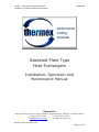
1
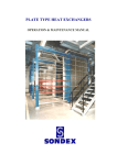
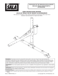
TTS005 – Gasketed Plate Heat Exchangers
Installation, Operation & Maintenance Manual
thermex Ltd
Gasketed Plate Type
Heat Exchangers
Installation, Operation and
Maintenance Manual
thermex Ltd
Merse Road, North Moons Moat, Redditch, Worcestershire. B98 9HL. United Kingdom
T +44(0)1527 62210
F +44(0)1527 60138
E [email protected]
W www.thermex.co.uk
Revision Date: December 2010
Page 1 of 23
TTS005 – Gasketed Plate Heat Exchangers
Installation, Operation & Maintenance Manual
thermex Ltd
Contents
1.
2.
3.
4.
FOREWORD
INTRODUCTION
SAFETY ALERT NOTICES
GENERAL
4.1.
Identification of the heat exchanger
4.2.
Correct operation
4.3.
Cautions
4.4.
Thermal design
5.
CONSTRUCTION
5.1.
Frame
5.2.
Plates
5.3.
Gaskets
5.4.
Special executions
5.5.
Right / left plates
6.
INSTALLATION
6.1.
Requirements of the installation area
6.2.
Transport, lifting & storage
6.3.
Installing the pipe connections
7.
COMMISSIONING & OPERATION
7.1.
Commissioning & pre-checks
7.2.
Operation
7.3.
Shut-down for short periods
7.4.
Shut-down for long periods
8.
MAINTENANCE
8.1.
Clean in place (CIP)
8.2.
Cleaning Detergents
8.3.
Opening the heat exchanger
8.4.
Cleaning the plates
8.5.
Plate replacement
8.6.
Gasket replacement
8.7.
Tightening & testing of the plate pack
8.8.
Maintenance of the heat exchanger
9.
PROBLEM SOLVING
10.
AFTER SALES SERVICE
10.1.
Ordering parts
10.2.
Modifications to the heat exchanger
10.3.
Contacts
3
3
3
4
4
4
5
6
7
7
7
7
8
8
10
10
10
12
13
13
13
14
14
15
15
15
16
17
18
18
19
20
21
23
23
23
23
Revision Date: December 2010
Page 2 of 23
TTS005 – Gasketed Plate Heat Exchangers
Installation, Operation & Maintenance Manual
thermex Ltd
1 FOREWORD
This manual is a guide for installation, commissioning and maintenance of plate type
heat exchangers supplied by Thermex.
It is meant for those who are responsible for the installation, the use and
maintenance of thsee heat exchangers. We recommend that you read this manual
carefully before commencing any work.
2 INTRODUCTION
This manual is applicable for all bolt-up plate type heat exchangers produced and
supplied by Thermex.
Thermex can not be held responsible or liable for damage as a result of
incorrect installation, use and / or maintenance of Thermex plate type heat
exchangers, or arising from non-compliance with the instructions in this
manual.
Please note that our plate type heat exchangers are specially designed and
built for the operating conditions (pressures, temperatures, capacities and
type of fluids) provided by the customer. Sudden pressure peaks beyond the
normal operating pressure (or pressure surges) which can occur during
starting up or stopping of the system can severely damage the heat
exchanger and should be prevented. Thermex can not be held responsible
for any damage as a result of any operation deviating from the original
design conditions.
If you wish to alter the design conditions, please contact us: refer to page 23 for
contact details. You may only commission the heat exchanger under the modified
conditions after inspection and written approval by Thermex. Also the name plate on
the heat exchanger will be adapted, modified or replaced.
3 SAFETY ALERT NOTICES
The following must be respected when installing, running or servicing Thermex plate
heat exchangers:
Observe current local safety regulations.
Ensure that the exchanger is depressurised and cooled to below 40ºC.
Use gloves to prevent any injury from sharp edges when handling plates.
In all cases ensure that all local health and safety and environmental protection laws
and regulations are strictly adhered to when working.
YELLOW TRIANGLE
Refer to applicable SAFETY ALERT notices within the manual!
All SAFETY ALERT notices are applicable to personal injury and
identified by this symbol.
Revision Date: December 2010
Page 3 of 23
TTS005 – Gasketed Plate Heat Exchangers
Installation, Operation & Maintenance Manual
thermex Ltd
4 GENERAL
4.1 Identification of the heat exchanger
All plate type heat exchangers supplied by Thermex are provided with a name plate.
On this plate the following details are specified:
• type of heat exchanger
• year of manufacture
• manufacturing number
• nominal capacity in kW
2
•
•
•
•
•
transmission area in m
max. working pressure in bar
test pressure in bar
max. working temperature in °C
min. assembling measure in mm
4.2 Correct operation
This user manual provides information and instructions for correct and safe operation
of the unit. Many accidents are caused by incorrect use! It is essential that you study
the instructions carefully, and above all ensure it’s availability to those who install,
maintain and operate the heat exchanger on a daily basis. This manual is of no
value if it is not available at the time when your staff need it.
If a problem occurs with your Thermex Heat Exchanger which is beyond the scope of
Revision Date: December 2010
Page 4 of 23
TTS005 – Gasketed Plate Heat Exchangers
Installation, Operation & Maintenance Manual
thermex Ltd
this manual, do not hesitate to contact us. The installation should not be put into
operation before all queries have been answered!
To avoid injury and damage, follow the instructions and local applicable health and
safety regulations. Also take the necessary protective measures, depending on the
nature of your process or circumstances related to it, at your plant.
Please note that our plate type heat exchangers are especially designed and built for
the operating conditions (pressures, temperatures, capacities and type of fluids)
provided by the customer. Sudden pressure peaks beyond the normal operating
pressure (or pressure surges) which can occur during starting up or stopping of the
system can severely damage the heat exchanger and should be prevented. Thermex
can not be held responsible for any damage which occurs as a result of any operation
deviating from the original design conditions.
If you wish to alter the design conditions, please contact us. You may only
commission the heat exchanger under the modified conditions after inspection and
written approval by Thermex. Also the name plate on the heat exchanger will be
adapted, modified or replaced.
4.3 Precautions
All potential personal injury hazards are identified by safety
alert symbol.
Bodily harm can be caused by:
• burning as a result of touching the heat exchanger or
other parts of the installation;
• the uncontrolled release of pressurised media with which
the danger of burning and other injuries is present;
• contact with chemicals;
• touching sharp edges of the installation.
Damage to equipment can be caused by:
• external forces;
• corrosion;
• chemical action;
• erosion;
• material exhaustion;
• water hammer;
• thermal and / or mechanical shock
• freezing;
• wrong transport / lifting.
Even after stopping the installation some parts of it can still be hot!
The heat exchanger may only be used with the fluids specified on the datasheet.
The hot medium may not flow through the exchanger without the cold medium
flowing through. This is to prevent damage to the exchanger. In case the cold
medium is present but does not flow while the hot medium is flowing through, the
cold medium will start boiling and the exchanger will be damaged.
Sudden pressure and temperature changes should be prevented.
Revision Date: December 2010
Page 5 of 23
TTS005 – Gasketed Plate Heat Exchangers
Installation, Operation & Maintenance Manual
thermex Ltd
When a heat exchanger (filled with water or a water mixture) which is not in
operation is exposed to temperatures below zero, the plates can become deformed.
If a danger of frost occurs, the heat exchanger should be drained completely.
Demountable plate heat exchangers can always leak. We advise you to take this
into account while installing. Preferably you should install a drip tray underneath the
heat exchanger to prevent leakages onto the floor and/or harm to electrical
equipment. (Short circuit/moisture damage).
If the heat exchanger is being used with temperatures above 60º C or with
aggressive fluids, we advise you cover the heat exchanger with a screen plate to
prevent the risk of touching.
If welding activities have to be carried out near the heat exchanger, never use the
heat exchanger for earthing the construction work. Electrical currents can cause
severe damage to both plate and gasket. If you have to carry out a welding
operation on the system which includes the heat exchanger, dismantle the
connecting flanges and isolate the heat exchanger from the system before starting
welding work.
4.4 Thermal Design
Thermex plate type heat exchangers are designed and calculated according to the
newest technology. If a performance test has to be carried out on the unit, the
exchanger must be totally clean before the test.
In the Thermex data sheet the nominal capacity and pressure losses are mentioned.
The pressure loss can deviate by up to 15 % from the data in the data sheet
depending on plate thickness, the plate material and the difference in the two
working pressures.
Revision Date: December 2010
Page 6 of 23
TTS005 – Thermex Plate Heat Exchangers
Installation, Operation & Maintenance Manual
5 CONSTRUCTION
5.1 Frame
The heat exchanger consists of a frame plate
(head), a pressure plate (follower), a carrying bar,
a lower bar and a column. Tie (clamping) bolts are
used to press the plate package together. The size
and number is depending on the type of heat
exchanger.
5.2 Plates
The plate package consists of plates with a groove
along the rim of the plate and around the ports. The
number of plates, their size and design, is dependant
on the thermal output required. Depending on the
application stainless steel or titanium plates might be
used
5.3 Gaskets
The groove provided in the plates holds the special
gasket. The purpose of this gasket is to prevent
intermixing of the media and leakage to the outside.
The gaskets are selected to suit the actual
combination of temperature, chemical resistance and
possible other conditions to be considered.
They can be supplied in Viton, Nitrile or EPDM.
Page 7 of 23
TTS005 – Thermex Plate Heat Exchangers
Installation, Operation & Maintenance Manual
The following types of gaskets are used in our plate type heat exchangers:
• Glue gaskets
• "Snap-in" gaskets
• "Lock-on" gaskets (new generation of gaskets)
• "Hang-on" gaskets
“Snap-in” gasket
“Lock” gasket
“Hang On” gasket
5.4 Special applications
If the plate heat exchanger works with several fluids at the same time, it may be
necessary to insert intermediate frames. The intermediate frames are equipped with
corner blocks which form the connections between the different sections. Two
connections can be placed in the same corner block with a connection to two
different sections in the plate heat exchanger.
For the exact application of your plate type heat exchanger please check the
documentation which was supplied with the heat exchanger.
5.5 Right/left plates
The heat exchanger plates are designed in such a
way that they can be used both as right and as left
plates. The plates just have to be turned 180º. (
Excepted are types S1, S53 and SF52, which are
“diagonal” plates. Here right and left plates are
different ).
Right and left plates:
• On a right plate the flow runs from hole 2 to
hole 3 or reverse from hole 3 to hole 2.
• On a left plate the flow runs from hole 1 to
hole 4 or reverse from hole 4 to hole 1.
Page 8 of 23
TTS005 – Thermex Plate Heat Exchangers
Installation, Operation & Maintenance Manual
The opening of the corner holes are described in a “plate code index”. For instance
1234 means that all corner holes are open. Every plate can be identified by the
gasket configuration, the plate code index and thermal short or thermal long
execution.
Plate Types
Start plate with gasket
Left hand flow plate with gasket
Right hand flow plate with gasket
Thermal long plate
Thermal short plate
Page 9 of 23
TTS005 – Thermex Plate Heat Exchangers
Installation, Operation & Maintenance Manual
6 INSTALLATION
6.1 Requirements in the
installation area
It is very important that enough space is
kept free around the heat exchanger for
servicing of the unit, including renewing
plates & gaskets and tightening of the
plate package.
As a rule of thumb the free space
around the unit should be 1.5 to 2x the
width of the unit.
6.2 Transport lifting and storage.
WARNING:
To prevent personal injury always
use appropriate hoisting equipment.
If you are lifting the heat exchanger
itself, straps should be used. They
should be placed as shown in the
picture at left.
Page 10 of 23
TTS005 – Thermex Plate Heat Exchangers
Installation, Operation & Maintenance Manual
Lifting:
Usually the heat exchanger will be supplied lying
horizontal on a pallet. The back side of the head
will then be strapped to the pallet. This allows
you to transport the unit easily by means of a
forklift truck.
Lifting of the unit:
• Remove all straps from the pallet.
• Place straps around one bolt on each side
as shown in the picture. NEVER use steel
cables or chains!
• Lift the heat exchanger from the pallet.
• Lower the heat exchanger slowly to the
vertical and onto it’s feet, locating it in it’s
installation position.
• Remove the lifting straps and secure the
heat exchanger to the floor
NEVER lift the heat exchanger using the
connectors or the studs around them.
Attention:
ALWAYS:
• Use the lifting eyes if fitted.
• Lift the top side of the head.
• Attached the straps to the bolts close to
the head.
NEVER:
• Lift using the connections.
• Lift with the follower plate.
• Lift using an intermediate plate.
• Lift with a strap attached close to the
follower.
Storage:
Should it be necessary to store the heat exchanger for a longer period (1 month or
more), certain precautions should be taken in order to prevent unnecessary damage
to the equipment.
Preferably the heat exchanger should be stored inside in a room with a temperature
around 15 to 20 ºC and a humidity of max. 70%. If this is not possible, place the
heat exchanger in a wooden box which is provided with a lining on the inside against
penetration of moisture.
It is not permissible to install the heat exchanger in a room containing
ozone producing equipment, including electric motors or arc-welding equipment,
since ozone destroys many rubber materials. Also do not store organic solvents or
acids in the room and avoid heat or ultraviolet radiation.
Page 11 of 23
TTS005 – Thermex Plate Heat Exchangers
Installation, Operation & Maintenance Manual
6.3 Installing the pipe connections
Depending on the type, the Thermex plate type heat exchanger will be provided with
flanges, couplings, threaded pipes, etc.
When connecting the pipe system to the heat exchanger make sure that no
stress or strain is imposed, by the pipe system, on to the heat exchanger!
We advise you of the following:
• Heavy pipe work needs to be supported. This will prevent excessive loading
on the heat exchanger.
• Always install flexible connections on the follower to prevent vibrations on the
heat exchanger.
o Flexible connections also prevent expansion of the pipe work, caused
by temperature influence, onto the heat exchanger.
o Flexible connections need to be fitted in a longitudinal direction to the
plate package.
• The pipe work needs to be thoroughly cleaned and flushed before connecting
up to the heat exchanger.
• Always install vents on both sides of the heat exchanger.
Note: For proper venting the vents should be fitted on the highest point in the
direction of the flow of the medium (preferably on an air vessel). To enable the heat
exchanger to be opened when necessary shut off valves should be provided in all
connections!
Make sure that the pipe work connected to the heat exchanger is protected
against pressure peaks / surges and temperature shocks!
Threaded pipe connections:
If a plate type heat exchanger is provided with threaded pipe connections, make
sure that these connections do not rotate when fitting to the pipe work. During
installation the threaded pipe on the heat exchanger should be supported to prevent
it rotating otherwise damage to the gasket on the start plate may occur.
Flange connections:
If the connection is rubber lined, the liner will act as the flange gasket. Bolt the
connecting flange directly to the endplate using the drilled and tapped holes
provided. Tighten the bolts evenly – do not over-tighten as this could strip the
threads cut into the frame plate.
If loose backing flanges are fitted to the heat exchanger a suitable gasket is
required to seal the flange.
Unless otherwise stated, the liquid circuits should be connected to flow in reverse
directions through the exchanger (counter-current). Refer to the contract drawing
or quotation details if the connections are not marked.
Page 12 of 23
TTS005 – Thermex Plate Heat Exchangers
Installation, Operation & Maintenance Manual
7 COMMISSIONING
7.1 Commissioning and pre-checks
Commissioning may only be done by staff specially trained for the job or by Thermex
approved commissioning engineers.
Control, maintenance and repair of the installation may only be done by authorized,
trained and properly instructed staff.
Maintenance and cleaning may only be done with a heat exchanger cooled to under
O
40 C and shut down!
Check and ensure that all connections are fitted correctly and to the correct ports
(see also 6.3).
Filtration: The media flowing through the heat exchanger should not contain particles
larger than 0,5 mm diameter/length. If necessary an inline filters should be fitted.
Check the pressures and temperatures of the media and make sure that these are
not more than the values specified on the name plate.
It is essential that the heat exchanger is not subjected to thermal or
mechanical shock as this could lead to premature gasket failure
7.2 Operation
Start cold circuit first, then the hot circuit.
•
•
•
•
•
•
Fully vent the system;
Close shut off valve fitted between pump and exchanger;
Fully open valve fitted into return line from the exchanger;
Start the circulation pump normally placed by the inlet;
Gradually open closed shut off valve between pump and exchanger;
Vent system again if necessary.
Repeat the above for the secondary circuit.
When using steam as one of the media:
Use slow acting steam control valves and open slowly shut off valves! Before start
up:
• Ensure that the steam control valve is fully closed;
• Ensure that the heat exchanger is fully drained of condensate ;
• Start cold circuit first, then the steam side;
• Open steam control valve slowly – this prevents water hammer of any
condensate in the steam line and reduces the pressure / thermal shock to the
exchanger;
• Ensure that the steam trap is correctly sized to allow full condensate
discharge – this prevents water clogging inside the exchanger.
Page 13 of 23
TTS005 – Thermex Plate Heat Exchangers
Installation, Operation & Maintenance Manual
Check for proper operation:
•
Check for pressure pulses in the system caused by the pumps or control
valves. If found, stop operation and rectify. Continuous pressure pulses will
result in fatigue failure of the plates.
Visually check the unit for leakages. Check that all vents are closed to prevent air
being sucked into the system.
When in operation, the conditions should not be changed. The maximum conditions
specified on the name plate should not be exceeded.
7.3 Shut-down for a short period
If the plate type heat exchanger has to be shut down for a short period, please
follow the following procedure:
• Slowly close the control valve in the hot circuit whilst maintaining the full
flow in the cold circuit;
• Switch off the hot circuit pump;
O
•
•
•
•
Cool down the heat exchanger to under 40 C;
Slowly close the control valve in the cold circuit;
Switch off the cold circuit pump;
Close all remaining shut off valves.
7.4 Shut-down for a long period
If the unit is to be taken off line for an extended period of time then the following
procedure should be followed:
Point 7.3 must be followed, then:
• Allow unit to cool down;
• Drain all circuits;
• Lubricate threads on the tie (clamping) bolts;
• Loosen tie clamping bolts until the plate pack is “loosened” (max. "A" size +
10%).
• The tie bolts should not be removed or loosened to such an extent that dirt is
allowed to enter in-between the plates. We recommend that a warning notice
is attached to the exchanger to remind personnel that the tie clamping bolts
need adjustment before the unit can be put back into service.
• Cover the plate pack with black plastic to exclude any sunlight.
Please also see chapter 6.2 – Storage
Page 14 of 23
TTS005 – Thermex Plate Heat Exchangers
Installation, Operation & Maintenance Manual
8 MAINTENANCE
8.1 CIP cleaning (clean in place by circulating cleaning detergents)
To use CIP cleaning, it is a condition that the scaling on the plates is soluble. All
materials in the whole circulation system of course have to be resistant to the
cleaning detergent.
We advise you to ask for a confirmation from the supplier of the cleaning
detergent that it will not damage the materials in the heat exchanger.
If the solution requires recirculation, select a flow that is as high as possible, and
certainly no less than the service or product flows.
Follow the instructions as given by the detergent supplier / cleaning specialist. We
suggest that for recirculated cleaning detergent methods, the fluid should be pumped
through the exchanger for no less than 30 minutes.
Rinsing After using any type of cleaning agent, always rinse thoroughly with
fresh water. If cleaning in place then circulate fresh water for at least 10
minutes.
8.2 Some Cleaning Detergents
Oil and grease can be removed with a water emulsifying oil solvent i.e. BP system.
Organic and grease cover can be removed with sodium hydroxide (NaOH) maximum
concentration 1,5% - max. temp. 85 ºC. Mixture for 1,5% concentration = 5 ltr. 0%
NaOH per 100 ltr. water.
Stone and limestone can be removed with nitric acid (HNO3) - max. concentration
1,5 % - max. temp. 65 ºC. Mixture for 1,5% concentration = 2.4 ltr. HNO3 62% per
100 ltr. water. Nitric acid also has an affective build up effect on the passivation film
of stainless steel!
CAUTION: Nitric acid and Sodium Hydroxide may cause
injury to exposed skin, eyes, and mucous membranes.
Use of protective eyewear and gloves is strongly
recommended.
Page 15 of 23
TTS005 – Thermex Plate Heat Exchangers
Installation, Operation & Maintenance Manual
8.3 Opening the plate heat exchanger
When
•
•
•
•
•
•
•
opening and assembling the heat exchanger observe the following:
Measure and note the actual "A" size;
Use the correct tools and lubricant;
Shut down the heat exchanger as described under 7.3;
Make sure the heat exchanger cools down (<40 ºC);
Ensure there is no pressure on any part of the unit;
Clean the tie (clamping) bolts and grease the threads;
Loosen the tie clamping bolts equally in the correct order (fig. 10) i.e. that the
follower shall have a parallel opening motion;
• Pull the follower back towards the column;
• Remove the plates without damaging the gaskets.
CAUTION: Ensure unit is depressurized and drained of
hot and/or aggressive product before unit is opened to
prevent personal injury.
CAUTION: Sharp edges. When handling plates, gloves
should be worn.
Recommendation:
Mark the plate package before opening.
You could mark the plate package with a diagonal line on the outside fig 10a, or
number the plates in sequence.
Page 16 of 23
TTS005 – Thermex Plate Heat Exchangers
Installation, Operation & Maintenance Manual
8.4 Cleaning the plates
CAUTION:
Always wear gloves
cleaning detergents.
and
eye
goggles
when
using
Use nylon or other types of “soft” scrubbing brushes with detergent.
Never use a metal brush, steel wool or sand/glass paper. This will damage
the passivation film of the plates.
Use Acetone or other types of solvents which do not contain chlorine to remove old
gasket glue. Alternatively use a ”lowtemp” gas flame softly heating the reverse
side of the plate. Do not use any other type of gas which may produce a “harder”
flame. Remember ventilation. Boiling water can be used with some success.
Consult a cleaning specialist for a suitable choice of detergent. Ensure that all detergents used are compatible with the plate and gasket material before use.
In case plates are removed for manual cleaning, make sure they are re-fitted in
the same order.
Always remove plates one by one and number them!
A high pressure cleaner can be used but with absolute care and never add abrasives.
If the scaling or organic layer is thick the plates can be put in a barrel with
qualified cleaning material.
Before fitting chemical cleaned plates they need to be thoroughly rinsed
with fresh water!
Important:
Cleaning is an important part, influencing the effectiveness of the plate heat
exchanger. Insufficient cleaning can have the following results:
•
•
•
too low circulation flow;
insufficient thermal output;
life time of the heat exchanger will be shortened.
If a plate has to be renewed because of serious damage, the plates next
to this plate normally need to be replaced.
Page 17 of 23
TTS005 – Thermex Plate Heat Exchangers
Installation, Operation & Maintenance Manual
8.5 Plate replacement
The plates must be clean, dry and free from oil or
grease. If there are any oil remains on the gaskets,
or on the gasket seating area, then there is a high
risk that the plates or gaskets shall slip out of place
when the unit is being tightened. If the gaskets are
contaminated with dirt or grit, then these could
cause leakage.
• make sure that all seating areas are flat, clean and
undamaged.
• always use new gaskets.
Fit the plates according to the Plate Sequence
Sheet – ensure all gaskets face towards the
fixed frame plate (head). Alternate between
left and right handed plates – if the plate
edges form a regular honeycomb pattern, the
left / right hand sequence is correct, see
fig.11.
8.6. Gasket replacement
Glue free gaskets
This type of gasket (“Hang-on”) and “Lock” (new generation of glue free gasket)
require no adhesive. They are located by pushing the gasket fully down into the
gasket groove or fastened by special devices. Make sure groove and gasket are
clean!
Glue type gaskets
The surfaces need to be clean and free of oil.
Only use chloride free glues like Pliobond 20 or 30, Bostic 1782,
3M EC 1099 and Bond Spray 77.
Follow the instructions of the manufacturer; these will be printed on the cover of the
glue.
CAUTION: When using commercial solvents and adhesives, follow
the manufacturers recommendations carefully, as many of these
materials are hazardous.
Page 18 of 23
TTS005 – Thermex Plate Heat Exchangers
Installation, Operation & Maintenance Manual
Ring Gaskets
The ring gaskets are used in connection with intermediate frames, by connections in
the follower and by ”SW” (Semi Welded) types. It can be necessary to use a little
glue for positioning the ring gasket during assembly of the heat exchanger.
Rubber Liners
There is one type of rubber liners for connections in the head an another type of
rubber liners for connections in the follower.
8.7 Tightening and testing of the plate pack
•
•
•
•
•
Lightly oil the tie (clamping) bolt threads. Do not allow oil or grease onto the
gaskets or the gasket seating faces on the back of the plates. Wet or
contaminated plates can be-come misaligned during tightening. In this case,
dismantle, clean, and dry all areas in contact with the gaskets. Evenly tighten
all bolts in the correct order (refer page 17 fig. 10). We advise the use of
ratchet spanners.
Ensure clamping is as uniform as possible, thus keeping the frames and plates
parallel throughout the operation. Avoid skewing the frame plates by more
than 5 mm.
Tightening is complete when the distance between the inside faces of both
frame plates equals the “A” distance as shown on the contract drawing, see
fig. 12. This tightening distance can also be calculated using the following
formula: Assembly distance = No. of plates x (plate thickness + coefficient)
o The coefficients can vary depending on the model type, but is often
0,1 mm.
Finally check that all tie (clamping) bolts are in tension and clean any spilt oil
off the head, follower and plates.
On completion the unit can be pressure tested (test pressure is stated on the
name plate).
Page 19 of 23
TTS005 – Thermex Plate Heat Exchangers
Installation, Operation & Maintenance Manual
If dimension "A" is not reached with application of maximum tightening torque:
• check the number of plates and dimension A on the data sheet;
• check that all the nuts and bearing boxes are running freely. If not, clean and
lubricate or replace.
If the unit does not fully seal, it may be tightened step by step to give dimension
“A” min. This dimension is mentioned on the name plate, see fig. 1. However, the
minimum measure must not be exceeded.
Under no circumstances distance “A” may be smaller than “A” min.
Tightening of the plate package can only be done with a fully depressurized
unit.
8.8 Maintenance of the heat exchanger
Time interval – once a year as a minimum
•
•
•
•
•
Check temperatures and flows against commissioning data.
Check general condition and look for any signs of leakage.
Wipe clean all painted parts and check surfaces for signs of damage – “touch
up” if necessary.
Check bolts and bars for rust and clean. Lightly coat threaded parts with
molybdenum grease or a corrosion inhibitor (ensure that no grease, etc. falls
onto the plate gaskets.
If rollers are fitted to the follower, lubricate the bearings with light machine
oil.
Page 20 of 23
TTS005 – Thermex Plate Heat Exchangers
Installation, Operation & Maintenance Manual
9 PROBLEM SOLVING
If you have problems with your plate type heat exchanger, in most cases these can
be solved by your own personnel. Please find below a summary of possible problems
as well as possible causes and solutions.
A condition for the continuous proper functioning of your plate type heat
exchanger is in strict compliance with the permissible values for pressure
and temperature mentioned on the name plate. Exceeding these values,
even as short-lasting pressure peaks will cause damage to the unit and be
the cause of problems.
To avoid costly repairs, we advise you to have the installation work and
maintenance carried out by properly trained personnel. You can also contact
relevant Thermex Sales Office.
Problem
Leakage
Possible cause
At the connections
Mixing of primary &
secondary circuit fluids
In the plate package
Operating conditions
deviate from specification
Insufficient
capacity
Air in the system
Operating conditions
deviate from specification
Too high
pressure drop
The heat exchanger is
dirty
The connections have
been interchanged
Flow exceeds the design
specification
Channels in plate(s)
blocked
Incorrect measurement
Medium deviating from
the design
Air in the system
Possible solution
Check the rubber liners (if fitted)
Check the flange gaskets (if fitted)
Check the O-ring – fit the pipes
tension free
Check the plates for holes and/or
cracks
Check the assembly distance ‘A’
Check the condition of the gaskets
Check the positioning of the gaskets
is correct
Adjust operating conditions to within
the specification of the heat
exchanger
De-aerate the pipe system
Check the pipework for possible air
traps
Adjust operating conditions to within
the specification of the heat
exchanger
Clean the heat exchanger
Check and redo the pipework if
necessary
Adjust the flow
Flush and/or clean the exchanger
Check the pressure gauge operation
Addition of (for instance) anti-freeze
will increase the pressure drop
De-aerate the pipe system
Check the pipework for possible air
traps
Page 21 of 23
TTS005 – Thermex Plate Heat Exchangers
Installation, Operation & Maintenance Manual
For nearly all leakage problems it will be necessary to dismantle the unit before any
attempts to rectify the fault can be made. Mark the area(s) where the leakage
seems to be with a felt tip marker or similar before taking apart the exchanger.
“Cold leakage” is caused by a sudden change in temperature. The sealing properties of certain elastomers are temporarily reduced when the temperature changes
suddenly. No action is required as the gaskets should re-seal after the temperature
has stabilised.
Gasket failures are generally a result of:
•
•
•
•
•
•
•
old age
excessive exposure to ozone
high operating temperature – above the temp. limit of the material
exposure to pressure surges
chemical attack
physical damage, resulting from incorrect assembly work, or damage
resulting from a misaligned plate (check the hanging system at the top of the
plate for distortion).
Decrease in performance is generally a result of:
•
•
•
•
•
•
•
•
•
•
•
•
plate surfaces require cleaning or de-scaling
pumps or associated controls have failed
plate channels blocked
liquid flows not as per design specification
associated chiller / cooling tower / boiler under sized or dirty
cooling water temperature to the exchanger is higher than the design
heating media temperature to the exchanger is lower than the design
steam flow not sufficient – control valve malfunction
steam trap broken or jammed – unit becomes filled with condensate
plate package has been assembled incorrectly
unit is running in co-current flow, instead of counter current – check with
contract drawing and alter pipe work if necessary. Check direction of pump
flows.
an air lock has developing in the plate package or pipe work.
Page 22 of 23
TTS005 – Thermex Plate Heat Exchangers
Installation, Operation & Maintenance Manual
10 AFTER SALES SERVICE
10.1 Ordering parts
When ordering parts it is important that the correct details are given.
At least the following should be quoted:
• Project and order number
• Exchanger type and manufacturing number (see name plate)
• Required parts
When ordering separate plates it is important that the correct plate code index and
type of plate is given. See chapter 5.2 When ordering separate gaskets it is
important to indicate the correct gasket material. When ordering tie (clamping) bolts,
the existing ones should be measured in order to get new ones of the same size and
length.
10.2 Modifications to the heat exchanger
The plate heat exchanger is built up in modules and therefore flexible with
respect to enlargements or reductions. It is easy to change the capacity by
respectively enlarging or reducing the number of plates. We would be pleased
to advise you.
10.3 Contacts
You can contact the factory as follows:
thermex Ltd
Merse Road,
North Moons Moat,
Redditch,
Worcestershire. B98 9HL
United Kingdom
Telephone
Fax
E-mail
+44(0)1527 62210
+44(0)1527 60138
[email protected]
International customers can also locate a local distributor via our website at
www.thermex.co.uk
Page 23 of 23