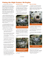
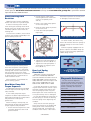
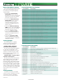
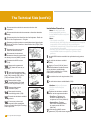
1
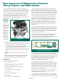
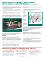
ServiceInsights
FOR
INDEP E N D E N T
S E RV I C E
C E NT E RS
J u l – S e p 2 0 11
> GM powertrain components . . . OE quality, value is obvious
> Help and resources available for reprogramming TCMs
> Visit ATRA and showcased GM transmissions
> New “modular” training clinics debut
> E-Rod mated to ’66 GTO without a hitch
> TechConnect insert with more valuable service info
More on the
inside including
powertrain repair
procedures.
CONTENTS
GM OE Service
Parts Update
3
The Technical
Side
The latest word on
product development
and technologies.
5
Discover new ways
to approach service
and repairs.
Repair Industry
News & Updates
4
Business
of Repairs
Get state-of-theindustry perspectives
from GM insiders.
9
New ideas that can
benefit how your shop
operates and profits.
GM ServiceInsights Online
More Genuine GM Parts
resources and links.
Download this issue and
past issues of
GM ServiceInsights
magazine at...
www.gmserviceinsights.com
GM ServiceInsights Headquarters
2604 N.E. Industrial Dr., #230
N. Kansas City, MO 64117
E-mail: [email protected]
Compliments of your GM dealer.
We invite your input and suggestions.
Please address letters to the editor to the above address. Letters submitted imply the right to edit and
publish. Every effort is made to ensure the accuracy of the information in the offers contained in this
magazine. However, printing and typographical errors may occur. These are not intentional and are not
the responsibility of GM, any GM dealer or the companies or individuals who create, produce and
distribute this magazine. Offers and pricing may change at any time without prior notification. The
descriptions and specifications in this publication were in effect at the time of approval for printing.
General Motors reserves the right to change specifications without notice and without obligation.
Published letters do not necessarily reflect the opinions of General Motors or General Motors Parts.
General Motors, Detroit, MI 48202.
© 2011 General Motors • All rights reserved.
GM OE Service Parts Update
Getting Specific
GM makes a case for the top quality and value
of competitively priced OE Service parts.
Words like “better,” “superior,” and “a cut above” are
typically used to describe original equipment parts. And for
good reason. OE parts are the real thing. Engineered for the
application by the same company that designed the vehicle,
they should perform better.
But exactly why and how are they superior?
GM has answered those questions directly with
documentation on specific advantages that some
OE Service parts (both GM and ACDelco brands) have
over aftermarket offerings. One quality shared by all
GM OE Service parts is a design based on the evaluation
of real-world product failures by GM Engineering and
rigorous durability testing.
In addition to the distinct design and durability
advantages of GM OE Service parts, GM has also made the
parts price competitive. Dealer-led competitive initiatives
and programs such as overPOWER the Competition are
convincing Independent Service Centers (ISCs) and vehicle
owners that they are better served by sticking with
OE Service parts.
For hard evidence, take a look at what GM is saying
about the specific comparative value of a few engine and
transmission components:
• Heat Treated Sun Shell Kit for 4L60E, 4L65E and
4L70E transmissions: Side-by-side spline wear durability
tests showed the OE Service part remained functional after
6 million cycles, while the aftermarket product failed
after about 700,000 cycles.
The reason: the heat-treated
teeth on the OE Service collar
stood up to wear because an
induction hardening process
is used. The aftermarket collar
failed much quicker because
the teeth became worn and
non-functional.
OE Service Heat Treated Sun Shell, part number 24228345, before and after the
durability test. The OES Service part remained functional after 6 million cycles.
Before the
durability
test.
After 6 million
cycles. Teeth on
the heat-treated
collar are still
intact and the part
remains functional.
• Engine Oil Cooler Lines: With pressurized lines,
form, fit and function are key. GM OE Service parts
are pre-bent to OE specifications, and thus don’t have
to be modified like aftermarket versions. They have proper
connections to guard against leaks and corrosion, use
specified materials for proper shielding and can incorporate
updates and upgrades.
• 4WD Actuator (Encoder) Motors: The GM OE Service
part is validated to perform with GM 4WD transfer case
systems and can be readily updated and upgraded. Encoder
sensors are available separately on many models. Lowerpriced aftermarket versions
have developed a reputation
for premature failure,
according to a recent
issue of Transmission
Digest magazine.
Up and down the
long list of GM engine
and transmission
components, the
story line is the same.
GM OE Service parts
are designed and built to
exacting specifications, and tests bear
out their superiority. Why would you settle
for anything less?
Jul – Sep 2011 ServiceInsights
3
Repair Industry News & Updates
GM TRANSMISSIONS
Present and Future —
on tap for ATRA show
Transmission specialists have a range of options to meet customer needs
today, and that full slate will be on display at the Automatic Transmission
Rebuilders Association show in Las Vegas in October.
2011 Hydra-Matic 6L50
(MYB) Six-Speed RWD
Automatic Transmission
4
Jul – Sep 2011 ServiceInsights
But if you’re a shop with a big share of GM business, a stop at the GM Powertrain booth could
leave you more time to do the fun stuff a show offers.
In addition to showcasing cutaways of six-speed transmissions and drive units used in hybrid
vehicles like the Chevrolet Volt, GM Powertrain will be talking up its transmission component
parts, its unbeatable warranty on remanufactured transmissions and the outstanding value that
GM original equipment parts offer.
The overarching message at the show, says Chris Thomas, product
development manager for transmissions for GM Customer Care and
Aftersales, will be that GM transmission solutions are hard to beat.
“We’ll be bringing the message to shop owners and techs that we have
a strong nationwide, 3-year, 100,000-mile warranty on plug-and-play reman
transmissions, and that we have a full range of component parts for rebuilding
jobs, some 300 of which are part of our overPOWER the Competition pricing
program,” Thomas says.
Even though reman jobs are growing more
popular, Thomas says GM continues to support
rebuilders. Information on the overPOWER program
that prices GM OE Service parts to compete with
aftermarket parts will be emphasized, he says.
GM will also use the ATRA opportunity to talk about the
future of transmissions, and how repair specialists will be
affected. In displaying the drive unit used in the Volt, GM
will be looking to better acquaint attendees with the drive
train technologies they’re likely to see more of in the future.
“This is another new age in transmissions coming around,
similar to the changes that swept the industry when automatic
transmissions were introduced,” Thomas says. “It’s important for
forward-leaning transmission specialists to take advantage of every
2011 Voltec Drive Unit 4ET50
opportunity to learn more about this new technology.”
(MKA) for Chevrolet Volt
The ATRA show will be held at the Hilton Hotel in Las Vegas Oct. 27-31.
It will be staged alongside the Automotive Parts Remanufacturers Association (APRA) expo.
The Technical Side
Resources and Tools Required
Many
resources
available to
help with
reprogramming
TCMs
In order to complete the R&R (Removal & Replacement)
process for a transmission that has a programmable
Transmission Control Module (TCM), technicians will need
to program the TCM for the specific vehicle being serviced.
There may also be a need to complete learn functions as
well as program other control modules.
“This is an important issue for technicians
because they are now servicing six-speeds
that are coming out of new car warranty.”
Chris J.Thomas, product development manager for
transmissions, GM Customer Care and Aftersales
2007 Hydra-Matic
6L80 (MYC) Six-Speed
RWD Automatic Transmission
GM Service Information (SI) Online
The R&R service procedure for the specific year make
and model detailing necessary calibration programming
and setup/learn procedures is available through ACDelco
Techconnect at www.acdelcotechconnect.com/html/
tss_tech_esi.jsp. Various types of subscriptions are
available based on individual shop requirements.
Service Programming System (SPS)
Calibration reprogramming is performed using
a combination of the Service Programming
Systems (SPS) application and the MDI vehicle
communication interface, Tech 2 scan tool,
or third party J2534 compliant vehicle
communication interface. SPS is a
web-based application.
Diagnostics/
Setup/DTCs
Tech2
Scan Tool
Depending on the vehicle, diagnostic
procedures and setup procedures are
performed with one of two solutions:
Multiple Diagnostic
Global Diagnostic Systems 2 (GDS2)
Interface (MDI)
and Multiple Diagnostic Interface (MDI)
are used for diagnostic and setup procedures of the
following vehicles.
• GDS2 is a web• Tech 2 supports:
based application. 1992 to 2012
2010 - Forward
Chevrolet Camaro
Chevrolet Equinox
Chevrolet Cruze
Chevrolet Volt
Buick LaCrosse
Cadillac SRX
GMC Terrain
Buick Regal
All other GM makes/models
Note: Third party aftermarket diagnostic
tools may support certain diagnostic
and setup procedures. Contact your tool
manufacturer for details and support.
The Tech 2 scan tool and MDI
vehicle communication interface can be
purchased through approved resellers
such as www.boschdiagnostics.com or
www.gmdesolutions.com
Courtesy of Mike Waszczenko,
brand quality manager,
GM Customer Care and Aftersales
Jul – Sep 2011 ServiceInsights
5
SPECIAL INSERT
The Technical Side (cont’d.)
2011
CHEVROLETCAMAROCONVERTIBLE
The segment-leading Chevrolet Camaro
opens a new chapter with the 2011 Camaro
convertible. A combination designed to
deliver sports coupe-like driving fun and
precise quality.
L99 6.2L V-8 VVT for the
Chevrolet Camaro SS
Two 6.2L V-8 engines are
offered in Camaro SS models,
including the L99 on
automatic-equipped
vehicles and the LS3 on
manual-equipped models.
Both engines are derived
from the LS3 that debuted
on the 2008 Corvette, with
an aluminum block (with cast
iron cylinder liners) and aluminum
cylinder heads. Horsepower for the L99 is 400 (298 kW)
and torque is 410 lb.-ft. (556 Nm). The LS3 develops
426 horsepower (318 kW) and 420 lb.-ft. (569 Nm).
All Camaro
models can be
equipped with
either a sixspeed manual
or six-speed
automatic
transmission.
The Aisin AY6
2011 Six-Speed
six-speed manual is
RWD Automatic
standard with the 3.6L engine,
Transmission (6L80) for
the Chevrolet Camaro
and a Hydra-Matic 6L50 six-speed
6
Jul – Sep 2011 ServiceInsights
automatic is optional. A Tremec TR 6060 six-speed manual
is standard on the SS, and the Hydra-Matic 6L80 six-speed
automatic is optional.
The Camaro convertible’s enhanced body structure
helps prevent cowl or steering wheel shake, for a strong,
confident feel in all driving conditions. The top has a
smooth, tailored fit with acoustical foam in the headliner
that helps deliver a quiet ride with the top up.
SPECIAL EDITION
2011 marks the
100th anniversary of
both Chevrolet and the
Indianapolis 500 and it was fitting
that a special-edition Chevrolet Camaro
Convertible was the official pace car at the
event. Chevrolet is producing 500 matching
replicas of this special Indianapolis 500 Pace Car so that
enthusiasts can purchase their own piece of history.
All the Indy Pace Car convertibles are Camaro SS models
equipped with the 6.2L V-8 engine, and the choice of a
six-speed manual or six-speed automatic transmission.
The electrification of the automobile
has been taking place for years, well
before today’s hybrid vehicles. More and
more electronic systems are becoming
commonplace, and as a result, more
complicated when it comes to electrical
system diagnosis. Did you know that
the Adaptive Forward Lighting system
on some GM vehicles automatically
changes light direction and intensity
based on speed, vehicle direction and
weather conditions?
Understanding the latest electrical
systems and how to diagnose them
is the focus of two new ACDelco
Instructor-Led Training (ILT) courses that
are available at local training centers. The
two new courses are Body Electrical:
Global Diagnostics, S-EL06-13.01ILT, and
Advanced Body Electrical System
Diagnosis, S-EL06-14.01ILT.
Body Electrical: Global
Diagnostics – S-EL06-13.01ILT
Body Electrical: Global Diagnostics
covers various electrical faults found
on electronic module networking,
intermittent electrical faults, and the
proper meter use – all designed to help
technicians improve their diagnostics
skills. In addition, it reviews the serial
data architecture of the new GM Global
Architecture (Global A) system.
In the course, technicians will:
7. Input signal circuits
• Diagnose electrical circuits using
a Digital Multimeter (DMM)
8. Output control circuits
• Review AC voltage circuits in
hybrid vehicles
9. Serial data circuits
Ground circuits, for example, are
becoming more important to proper
• Perform the ground credibility test
and other electrical tests
• Identify serial data circuits
• Learn how to use power moding
in module diagnostics
• Review terminal fretting and its
effect on electrical circuits
Circuit Testing
One testing procedure highlighted
in the course covers testing circuit
functions in sequence until a fault is
detected. Knowing how the testing
procedure works enables technicians
to apply the same knowledge to any
version of a given circuit type. There are
nine circuit functions to test:
continued on page 3
IN THIS ISSUE
New ACDelco Electrical
System Diagnosis Training . . . . . . . . . . . . . . .1
Outside Air Temperature
Display Operation. . . . . . . . . . . . . . . . . . . . . . . 2
New Compressed Natural Gas-Powered
Chevy Express and GMC Savana . . . . . . . . .4
New Heavy-Duty Cooling
System Cleaner . . . . . . . . . . . . . . . . . . . . . . . . .5
Timing the High Feature V6 Engine . . . . . . . .6
Tech Tips . . . . . . . . . . . . . . . . . . . . . . . . . . . . . .7
Training Update . . . . . . . . . . . . . . . . . . . . . . . .8
1. Ground circuits
2. Low reference circuits
ON THE WEB
3. Battery positive (B+) circuits
4. Ignition circuits
5. AC voltage circuits
6. Reference voltage circuits
– www.acdelcotechconnect.com, click
the TechConnect Magazine link, or
– Log in to the ACDelco LMS, click the
Resources link
Outside Air Temperature
Display Operation
The outside air temperature is displayed on the Driver Information Center, radio
or rear view mirror in a number of GM vehicles. There may be some confusion
about the operation of the display and how quickly it updates ambient temperature. Depending on several factors, the temperature may not be updated immediately and owners may feel that the display is inaccurate at times.
As an example, here’s a look at the operation of the outside air temperature
display on several GM small cars from recent model years (2004-2010 Chevrolet
Malibu; 2005-2010 Chevrolet Cobalt and Pontiac G6; 2006-2011 Chevrolet HHR;
and 2007-2010 Saturn AURA).
The ambient air temperature sensor is a variable resistor interfaced to the Body
Control Module (BCM). The ambient air temperature sensor is a 2-wire negative
temperature coefficient thermistor.
The BCM applies 5 volts to an internal input resistor connected to the signal
circuit of the ambient air temperature sensor. The BCM also provides the ground
to the ambient air temperature sensor through the low reference circuit. When
the ambient air temperature is cold, the sensor resistance is high and the signal
voltage is high. When the ambient air temperature is hot, the sensor resistance
is low and the voltage signal is low.The BCM provides the logic for reading the
ambient air temperature sensor, filtering the data and transmitting the information
via the serial data circuit to the outside temperature display. The outside air
temperature algorithm uses three pieces of information: outside air temperature
data, vehicle speed, and the time
the engine was turned off.
The main source of variation
between actual outside temperature
and the reading inside the vehicle is
the variable airflow across the sensor
at low vehicle speed and stopped
conditions. At higher speeds, when
more airflow is moving through the
front of the vehicle, a more accurate
indication of actual air temperature
is provided.
When the engine is first started,
the algorithm looks at how long the engine was off and if the outside temperature
is lower than the last reading taken during the previous ignition cycle. From this
information, it’s determined if a new outside temperature reading should be taken.
If the engine was off long enough or the current outside air temperature is
cooler than the stored value, a new outside temperature reading is taken and
displayed. If the engine was not off long enough or the current outside air
temperature is higher than the stored value from the previous ignition cycle,
the last stored value of outside air temperature taken will be displayed.
The outside air temperature will continue to be updated every second as long
as the outside air temperature is the same or cooler than the previous reading.
Once the new outside air temperature reading exceeds the previous temperature
and the vehicle is traveling less than 18 mph (29 km/h), the displayed outside air
temperature will remain at its last value. Once the vehicle speed exceeds 18 mph,
the displayed outside air temperature will be updated. If the speed drops below
18 mph, the outside air temperature will freeze at its last value.
When using a scan tool during diagnosis, it is possible that the temperature
reading on the scan tool will differ from the temperature displayed on the
DIC/radio without there being a problem with the vehicle. The DIC/Radio only
displays the reading being sent from the BCM.
– Thanks to Ernest Haller
2 TECH CONNECT
ACDelco TechConnect is published bi-monthly
and online for technicians and Key Fleet
accounts to provide timely service information,
increase knowledge and improve the
performance of the service center.
ACDelco 360 represents our mission to look at
our businesses at every possible angle to provide
value and assistance to our distributors and
their customers as well as offer a full circle
of support with programs, tools, training and
marketing focused on enhancing and growing
our partnership successfully.
Publisher:
Mike DeSander
ACDelco
E-mail
[email protected]
Editor:
Mike Militello
ACDelco
E-mail
[email protected]
Technical Editor:
Mark Spencer
E-mail
[email protected]
Production Manager:
Marie Meredith
Desktop Publishing:
5by5 Design LLC
E-mail
[email protected]
Write to:
ACDelco TechConnect
P.O. Box 500
Troy, MI 48007-0500
On the Web:
To read and search recent issues of
TechConnect online:
– www.acdelcotechconnect.com,
click the TechConnect Magazine
link, or
– Log in to the ACDelco LMS, click
the Resources link
ACDelco service tips are intended for use by
professional technicians, not a “do-it-yourselfer.”
They are written to inform those technicians of
conditions that may occur on some vehicles, or to
provide information that could assist in the proper
service of a vehicle. Properly trained technicians
have the equipment, tools, safety instructions and
know-how to do a job properly and safely. If a condition is described, it cannot be assumed that the
information applies to all vehicles or that all vehicles
will have that condition.
All materials and programs described in this
magazine are subject to change. Submission of
materials implies the right to edit and publish.
Inclusion in the publication is not necessarily an
endorsement of the individual or the company.
TechConnect is published for ACDelco by Sandy
Corporation, Troy, MI.
©2011 ACDelco. All rights reserved.
New ACDelco Electrical System Diagnosis Training
— continued from page 1
Networks
The communication networks highlighted in the course
include GMLAN, local interconnect network, CAN graphical
interface, class 2, UART and the new Global Architecture.
Taking a closer look at the Local Interconnect Network
(LIN), technicians will learn that this network bus transmits
serial data over a single wire network circuit bus between a
primary control module and other control modules within a
particular subsystem. The LIN bus is not exposed t the rest
of the vehicle’s main communication bus. LIN slaves communicate only to the master module for the network, not to
other control modules on the vehicle.
Common grounds
diagnosis as more and more electrical components share a
common ground. Statistically, ground circuits are the most
often overlooked when diagnosing electrical concerns.
With Electronic Control Unit-based electrical systems,
high resistance in ground wire connections can produce
conditions such as cranking difficulties or improper injector
triggering.
Intermittent Conditions
Another topic covered in the course, intermittent diagnosis, examines the different types of intermittent fault
conditions. These can include terminal fretting and deformation, bussed electrical center terminal contact, and hot and
cold temperature sensitivity.
Terminal deformation can occur when probing the mating
side of the connector terminal without the proper adapter,
which results in poor terminal contact and causes an open
or intermittently open circuit. Use the proper terminal
probe adapter from a terminal probe test kit when checking
terminals.
Advanced Body Electrical System Diagnosis –
S-EL06-14.01ILT
Advanced Body Electrical System Diagnosis focuses on
various procedures and diagnostics for Body Control Module
(BCM) and non-BCM body electrical systems, such as power
windows, power locks and lighting as well as keyless entry,
RainSense wipers and Ultrasonic Rear Parking Assist.
Local Interconnect Network
The course also covers the operation of a number of
circuits for various body components. One example reviews
the power door lock circuits, including the master/slave
data transmission and free-flow data transmission.
Free-Flow Communication
On some vehicles, the power door lock system may
include the Driver Door Switch, Passenger Door Switch,
Body Control Module, Driver Information Center, Rear Door
Lock/Unlock Relay and the reversible door lock actuators in
each door. The modules that activate the power lock motors
are the driver door lock actuator, passenger door lock actuator and the Body Control Module (rear door lock actuators).
• Communication networks
Operation can be controlled by several actions, which the
modules are looking for at all times. If the front door lock
switch provides direct input to the driver door lock actuator,
a LAN message is sent that indicates the door lock switch
position. The module that activates the power door lock
motor receives the LAN message and activates the motor in
the appropriate direction.
• Global Service Information
Learn More
• Power window and sunroof circuits
In addition to the new electrical system diagnosis courses,
ACDelco offers on-demand, online, Web-based courses,
instructor-led Virtual Classroom Training courses and a variety
of other instructor-led, hands-on courses at training centers
around the country. To review the latest training courses
available, log in to the ACDelco Learning Management
System (LMS) at www.acdelcotraining.com.
– Thanks to Rick Balabon
Participants in the course will cover:
• Various communication networks
• Electrical grounds and voltage circuits
• Keyless entry systems and locking functions
• Lighting operation
• Identify BCM starting system circuitry
• Review the radio theft lock system and active noise
cancellation
3 TECH CONNECT
New Compressed Natural Gas-Powered
Chevy Express and GMC Savana
GM is introducing a dedicated compressed natural gas
(CNG) system available on full-size Express and Savana cargo
vans for fleet use. The CNG option will be available on 3/4 ton,
135-inch wheelbase and 1 ton, 135-inch wheelbase models.
This new CNG option adds to GM’s position as an alternative fuels leader. From 1997 to 2007, GM built more than
23,800 CNG or liquefied petroleum gas (LPG) vehicles.
Chevrolet and GMC are the only brands to offer a one-source
CNG option on vans for fleet customers.
CNG 6.0L
V8 Engine
The CNG
vans are
equipped with
a Vortec 6.0L
V8 (RPO LC8).
It maintains
the same
horsepower
(323 hp @
4,600 rpm)
and torque
(373 lb.-ft. @
4,400 rpm)
rating as the
6.0L V8 gasoline engine.
The CNG fuel system has four tanks with a 23 gasoline
gallon equivalent (GGE) capacity. The first tank (6.4 GGE) is
located under the center of the vehicle in place of the regular
fuel tank. There are two tanks (4.9 GGE and 4.5 GGE) mounted where the spare tire normally is located at the rear of the
vehicle. The fourth tank (7.2 GGE) is mounted on the cargo
floor in an enclosure, inboard of the left rear wheelhouse.
The fuel storage system provides fuel system corrosion
resistance and fuel system integrity that exceed Federal
Motor Vehicle Standards. Federal regulations require that the
fuel tanks and brackets be inspected every three years or
36,000 miles (60,000 km), whichever occurs first. The service life of the type 1 CNG fuel tanks is 15 years from the
date of manufacture, after which, they must be removed
from service.
There are four externally mounted pressure relief devices
(PRD). Two are equipped with a thermally-activated PRD, one
with a combination temperature and pressure valve, and one
with a pressure operated burst disc. The burst disc activates
when CNG tank pressure becomes too high for safe operation (approximately 5,400 psig).
All external PRDs are connected to fuel storage pressure
and cannot be isolated from the high pressure system.
Service should not be attempted on these devices or
connecting tubing/hoses unless it’s absolutely certain that the
system is completely empty of CNG fuel.
Vortec 6.0L V8
Enhancements made to the engine to run on CNG include:
• Hardened engine components for higher wear resistance
and durability required in the gaseous fuel system
– Exhaust valve materials resist higher temperatures and
the corrosive nature of propane and natural gas
– Intake and exhaust valves feature a special insert that
ensures an excellent seal between the valve and valve
seat
• Dedicated gaseous fuel injection and engine control
module
• Engine performance designed to meet Environmental
Protection Agency (EPA) and California Air Resources
Board (CARB) emission certification requirements
Fuel System
The CNG fuel system consists of:
• Four CNG fuel tanks
• CNG fuel tank pressure relief device (PRD)
• CNG fill receptacle and fill line
• CNG fuel tank high pressure lock-off (HPL)
solenoid valves
• CNG fuel tank pressure (FTP) sensor
• CNG fuel lines
• CNG 1/4 turn isolation valve
• CNG fuel filter
• CNG high pressure regulator (HPR)
Four CNG tanks have a 23 GGE capacity.
The CNG fuel lines consist of different fuel line types based
on the working pressure and vehicle interface requirements.
The high pressure and low pressure CNG fuel lines and hoses
are a combination of stainless steel tubing and stainless steel
jacketed PTFE (polytetrafluoroethylene). All connections
between lines and components are sealed by O-rings
specifically designed for CNG operation.
The high pressure CNG fuel system is equipped with a
manually operated 1/4 turn isolation valve. The valve is located
forward of the rear wheel on the driver’s side of the vehicle
atthe inboard side of the LH frame rail. The valve can isolate
the high pressure side of the fuel system for some service
procedures. If the valve is inadvertently left in the Off position, the vehicle will not operate.
The CNG fuel filter, a high pressure coalescing media filter,
is located forward of the CNG 1/4 turn isolation valve. It
requires periodic service intervals.
Fuel flow begins when the ignition is cycled and the high
pressure lock-off (HPL) and the high pressure regulator (HPR)
solenoids open. The HPR is supplied with fuel at pressures up
continued on page 5
4 TECH CONNECT
New Compressed Natural Gas-Powered
Chevy Express and GMC Savana — continued from page 4
to 3,600 psig (pound-force per square inch gauge), or 24,821
kPa (kilopascal), at 70°F (21°C). The outlet pressure is regulated to 90-110 psig and delivered through the low pressure lines
to the fuel rail and CNG injectors.
The CNG fuel injectors are installed in the base vehicle fuel
rail and require spacers between the injector and manifold
injector boss.
The ECM controls fuel delivery in the same manner as a
gasoline vehicle. The CNG fuel system also features the same
powertrain diagnostics and use of the Tech 2 scan tool as a
gasoline engine. There are not any new Diagnostic Trouble
Codes. Follow the standard repair protocol as with a gasoline
vehicle. Refer to the appropriate GM Service Information for
specific CNG information.
A. 1/4 turn isolation valve
B. Fuel filter
C. High Pressure Regulator
otherwise, natural gas can leak while refueling. The vehicle is
shipped with three replacement O-rings in the storage bin on
the engine cover.
It should take about 6-8 minutes to fill the fuel tanks at a
fuel station for natural gas vehicles. Refueling will stop
automatically when the tanks are full.
CNG
quantity is
affected by
changes in
fuel temperature and fuel
pressure.
When refueling in cold
ambient conditions, the
fuel gauge
may not
display FULL
even though
the temperaCNG fill receptacle sealing O-ring
ture-compensated refueling
event produces a temperature-compensated FULL condition.
This is due to commercial refueling station output regulated
by a temperature vs. pressure strategy to prevent the vehicle
from becoming over-pressurized if relocated to a warmer
ambient location after refueling.
Operating Tips
When the fuel supply system needs to be opened, the
pressure in the lines must be relieved before attempting
repairs. Refer to the Service Information for the low-pressureside and high-pressure-side relief procedures.
Refueling
With an estimated mpg of 11 city/16 highway, the four
tank design with a 23 GGE capacity provides a range of
approximately 250 to 360 miles. The system is designed to
be filled at a 3,600 psi (24,800 kPa) station (yellow handle on
fill nozzle). It can be filled at a 3,000 psi (20,684 kPa) station
(blue handle on fill nozzle), but this will result in a reduced
range and a fuel gauge reading of approximately 7/8 full.
The CNG fill receptacle is a NGV1 profile and mates to
any NGV1 fill dispenser valve. The fill dispenser seals to the
receptacle with an O-ring. Replace the O-ring in the fill
receptacle before refueling if it is damaged or missing;
The extra hardware needed for the CNG system adds
approximately 800 lbs. to the weight of the vehicle. This
additional mass reduces the payload capacity. This should be
noted when loading the vehicle. The G23405 model (3/4 ton)
has a payload capacity of 2,409 lbs. and the G33405 model
(1 ton) has a payload capacity of 3,374 lbs.
Extreme cold weather (below –4°F, –20°C) may make it
harder to start the engine. If the vehicle will be driven regularly in cold temperatures, it will be necessary to use the
standard engine block heater.
Routine maintenance schedules (fluids, filters, etc.) for the
CNG vans are designed to follow the original specifications
for the gasoline-fueled vans. The Owner Manual lists the
recommended maintenance service intervals and fluid
specifications.
– Thanks to Chris Graham
New Heavy-Duty Cooling System Cleaner
A new heavy-duty cooling system
cleaner is now available from ACDelco
that is safe for removing rust, scale and
deposits, including silicate gel, from the
cooling system quickly and effectively.
This product contains a detergent that
removes oil and grease along with a
corrosion inhibitor to reduce corrosion
of engine metals during the cleaning
process.
The heavy-duty cooling system
cleaner, part number is 10-5037, is
available in a package of six 16-ounce
5 TECH CONNECT
containers. Contact your DDG or local
ACDelco representative to order.
Refer to ACDelco Bulletin 11D-032 for
more information.
– Thanks to Mike DeSander
Timing the High Feature V6 Engine
The following GM models offer
the available high feature 3.6L V6
engine (RPO LY7, LLT), 2.8L V6 engine
(RPO LP1) or 3.0L V6 engine (RPO LF1,
LFW): 2007-2011 GMC Acadia, Buick
Lacrosse, Cadillac CTS, SRX and STS;
2007-2009 Pontiac G6 and Saturn
AURA; 2007-2010 Saturn OUTLOOK;
2008-2009 Pontiac Torrent; 2008-2011
Buick Enclave, Chevrolet Malibu and
Equinox; 2008-2010 Saturn VUE; 20102011 Chevrolet Camaro; and 2011
Chevrolet Traverse.
Stage One Timing
Stage Two Timing
To set the timing on a high feature V6
engine, start with the engine in stage
one position with tool EN 46105-1,
Camshaft Locking Tool, or EN 48383-1,
Camshaft Retaining Tool, on the left
bank, or bank 2. The circular timing
marks on the camshafts should be
aligned as shown.
The engine will need to be rotated
115 degrees clockwise for stage two
timing. The crankshaft marks should
align dot to dot. Tool EN 46105-2 or EN
48383-2 should fit easily on the rear of
the cams on the left bank of the
engine.
The painted link should be visible
through the hole of the intermediate
gear for the left secondary chain.
The high feature V6 engine family
features a camshaft drive system that
consists of a primary timing drive chain
driven by the crankshaft sprocket. The
primary timing drive chain drives two
intermediate drive shaft sprockets. Each
intermediate drive shaft sprocket drives
separate secondary timing drive chains,
which drive the respective cylinder
head's intake and exhaust camshaft
position actuators.
The following supplemental information may be helpful when timing the
high feature V6. Refer to the appropriate Service Information for complete
timing procedure information.
Keep these items in mind before
beginning the timing procedure:
• In a front-wheel-drive vehicle, it
may be easier to remove the
engine before beginning.
• When removing the front cover, be
sure to remove the belt tensioner
and all the bolts. Damage may
occur to the block if this procedure
is not followed.
In stage two position, the crankshaft
marks should align dot to dot.
In stage one position, the circular timing
marks on the camshafts should be aligned.
EN 48383-3 should be installed on
the right bank, or bank 1. The triangular
marks should be aligned.
Stage one primary chain alignment
for the crankshaft and the left intermediate gear is shown below. The intermediate gear has a triangular shaped timing mark that aligns with the painted
link and the crankshaft has a dot-to-dot
alignment.
The painted link on the right intermediate shaft should be aligned with the
hole in the rear gear.
The left camshafts will be aligned as
shown when in stage two timing position.
The right intermediate gear has a triangular mark that aligns with the painted link.
• When removing the front cover, do
not pry against or strike the cam
actuators. This will cause damage
to the reluctor or actuator.
• Intake cam actuators have marks
on them for the Right Bank (R) and
the Left Bank (L). They must be
positioned respectively.
• Be sure to note the orientation of
the injector wiring harness. The
harness with connector should
come out on the front side of the
engine. If installed backwards it
will cause misfires and/or fuel
trim DTCs.
• 4 screw Delphi and 5 screw Aisin
cam actuators are interchangeable,
but will require the correct shim
behind them when applicable. 4
screw Delphi actuators use a 0.043
in. shim and the 5 screw Aisin
actuators use a 0.063 in. shim.
The left camshafts will be aligned when in
stage two timing position.
The intermediate gear has a triangular
shaped timing mark that aligns with the
painted link and the crankshaft has
a dot-to-dot alignment.
Remove EN 46105-1 or 48383-1 from
the left bank.
6 TECH CONNECT
If there are any concerns in identifying the correct location for the
camshafts, check the number stamped
in the rear of the camshaft — RI is right
intake, RE is right exhaust, LI is left
intake and LE is left exhaust.
– Thanks to James Bloss
The following technical tips provide repair information about specific conditions on a variety of vehicles. If you have a tough or unusual
service repair, the TSS Technical Assistance Hot Line can help. Call 1-800-825-5886, prompt #2, to speak with a technical
expert with the latest OEM information.
Power Steering Fluid
Restrictor
2003 Chevrolet Cavalier and Pontiac
Sunfire with the 2.2L 4-cylinder engine
A rattle or knocking noise noticed
when turning the steering wheel while
driving slowly over rough roads may be
caused by hydraulic noise within the
steering rack.
2. Ensure that the water pump
mounting bolt holes in the front
cover are completely clean
and dry.
are either not present or severely worn
or damaged, install new inserts.
3. Place a new water pump gasket
on the water pump.
4. Place the water pump in position
on the front cover.
5. Install the water pump bolts
finger tight.
To correct this condition, install a fluid
restrictor, part number 22592200, in the
power steering return line.
Light-duty rear leaf spring tip inserts
On some models, the vehicle may
have to be raised to allow the springs to
separate enough so the insert can be
installed.
Vehicles originally equipped with all
plastic or plastic and rubber design tip
inserts can be serviced by updated all
rubber design inserts.
Tighten the water pump bolts in sequence.
A. Power steering pump
B. Power steering return hose
Remove the power steering return
hose from the power steering pump.
Install the fluid restrictor in the power
steering fluid reservoir return port. The
inlet and outlet hoses must not be
twisted during installation. Do not bend
or distort the inlet or outlet hoses to
make installation easier.
After installation, fill and bleed the
power steering system.
New Water Pump Bolt
Torque Sequence
All 2004-2012 GM vehicles equipped
with the High Feature V6 engine (2.8L,
3.0L, and 3.6L).
A new water pump bolt torque
sequence has been implemented on all
High Feature V6 engines to help reduce
the potential for water pump
gasket leaks.
When installing a water pump, use
the following revised water pump bolt
torque sequence and procedure:
1. Ensure that the engine front cover
and water pump are clear of old
gasket material.
6. Tighten the water pump bolts in
sequence to 12 N·m (106 lb. in.).
7. Tighten the water pump bolts a
second pass in sequence to 12
N·m (106 lb. in.).
Rear Leaf Spring
Clunk Noise
1999-2011 Chevrolet Silverado and
GMC Sierra 1500/2500; 2000-2011
Chevrolet Suburban and GMC Yukon XL
2500; 2002-2006 Chevrolet Avalanche
2500; 2003-2011 Chevrolet Express and
GMC Savana 2500/3500 vans with
8500 GVWR, 8600 GVWR or 9600
A rear leaf spring slap or clunk noise
may be heard when the vehicle is operated over irregular road surfaces. The
rear leaf spring tip inserts may have
broken apart from wear and fallen out,
or may be severely worn or damaged.
Do not disassemble the main pack on
the leaf spring or remove the bushing
from the spring when diagnosing this
condition.
Verify that the rear leaf spring tip
inserts are present on the leading and
trailing ends of the overload spring
(second stage leaf), and inspect the
condition of the inserts. If the inserts
7 TECH CONNECT
A. Plastic tip insert
B. Plastic and rubber tip insert
C. All rubber tip insert
Diagnostic Assistance
For free technical diagnostic
assistance and product information
regarding specific ACDelco products,
contact these toll-free information
hotlines staffed by ASE-certified
technicians:
Brakes – 1-888-701-6169 (prompt #1)
Chassis – 1-888-701-6169 (prompt #2)
Clutches – 1-888-725-8625
Lift Supports – 1-800-790-5438
Shocks – 1-877-466-7752
Starters and Alternators –
1-800-228-9672
Steering (Pumps, Rack and Pinion,
Gears) – 1-866-833-5567
Wiper Blades – 1-800-810-7096
How to Take ACDelco Training
Current Virtual Classroom Training
Go to www.acdelcotechconnect.com
and click the Training tab to log in to
the ACDelco Learning Management
System (LMS).
FVCT1.09V
How to Use VCT – Recorded
S-AC07-01.01VCT
HVAC System: Components and Lubricants
• To enroll in an Instructor-Led
Training (ILT) course, click the
Enrollment link or the Instructor-Led
Courses link to view the catalog
and select a specific course.
• To enroll in a Virtual Classroom
Training (VCT) course, click the
Enrollment link or the Virtual
Classroom Training Courses link
to view the catalog and select a
specific course.
• To launch a Web-Based Training
(WBT) course, click the Web-Based
Courses link to view the catalog
and select a specific course.
• To launch a TechAssist (TAS)
course, click the TechAssists link
to view the catalog and select a
specific course.
• To launch a Simulation (SIM),
click the Simulations link to view
the catalog and select a diagnostic
challenge simulation.
Course Number
Course Name
S-AC07-01.01VCT-R
HVAC System: Components and Lubricants – Recorded
S-AC07-02.01VCT
HVAC System: Operation and Service Hints
S-AC07-02.01VCT-R
HVAC System: Operation and Service Hints – Recorded
S-AC07-03.01VCT
HVAC System: Flushing, Recovery and Diagnostics
S-AC07-03.01VCT-R
HVAC System: Flushing, Recovery and Diagnostics – Recorded
S-AC07-04.01VCT
HVAC System: Engine Cooling, Controls and Communication
S-AC07-04.01VCT-R
HVAC System: Engine Cooling, Controls and Communication – Recorded
S-EL06-01.01VCT
Electrical Circuit Function and Diagnosis
S-EL06-01.01VCT-R
Electrical Circuit Function and Diagnosis – Recorded
S-EL06-02.01VCT
Testing Electrical Signal and Control Circuits
S-EL06-02.01VCT-R
Testing Electrical Signal and Control Circuits – Recorded
S-EL06-03.01VCT
Serial Data Communication Networks
S-EL06-03.01VCT-R
Serial Data Communication Networks – Recorded
S-EL06-04.01VCT
Communication Network Diagnosis
S-EL06-04.01VCT-R
Communication Network Diagnosis – Recorded
S-EM01-01.01VCT
Camshaft Position Actuator Systems
S-EM01-01.01VCT-R
Camshaft Position Actuator Systems – Recorded
S-EM01-02.01VCT
Active Fuel Management Operation
S-EM01-02.01VCT-R
Active Fuel Management Operation – Recorded
S-EM01-03.01VCT
Active Fuel Management Diagnosis
Training Spotlight
S-EM01-03.01VCT-R
Active Fuel Management Diagnosis – Recorded
The following new or updated
ACDelco training programs have
recently been made available:
S-FN00-01.01VCT
How to Use VCT
S-EL06-11.02ILT – Enhanced
Automotive Circuit Diagnosis
This ILT course emphasizes diagnostic skills that are applicable to the
complex electrical systems on newer
vehicles. It includes a review of GM
North American wiring diagrams and
the new global format.
Current Instructor-Led Training
Course Number
Course Name
S-AC07-02.01ILT
Automotive Air Conditioning: Advanced Refrigerant System Diagnostics
S-AC07-03.01ILT
HVAC Control System Operation and Diagnostics
S-BK05-01.01ILT
Braking Systems
S-BK05-02.01ILT
ABS Operation and Diagnosis
S-EL06-04.02ILT
Network Communication Diagnosis
S-EP08-81.02ILT – Duramax Diesel
Operation and Diagnosis
This ILT course covers the Duramax
diesel engine evolution from 2001 to
2011, including an overview of the
Duramax features and design changes
for all engine applications. The course
also covers the engine control management system, the fuel delivery system
and the variable geometry turbocharger
as well as the features of the aftertreatment system of the new Duramax
engines.
S-EL06-10.02ILT
Electrical Power Management
S-EL06-11.01ILT
Automotive Electrical Circuit Diagnosis and Repair
S-EL06-11.02ILT
Enhanced Automotive Circuit Diagnosis
S-EL06-12.01ILT
Hybrid Technology and Service
S-EL06-13.01ILT
Body Electrical: Global Diagnostics
S-EL06-14.01ILT
Advanced Body Control System Electrical Diagnostics
S-EP08-02.01ILT
Engine Performance: Computer Controls and Ignition System Diagnostics
S-EP08-03.01ILT
Engine Performance: Air Induction and Fuel System Diagnostics
S-EP08-04.01ILT
Engine Performance: Fault Monitoring and Emission System Diagnostics
S-EP08-05.01ILT
Engine Performance: Advanced Drivability Diagnostics
S-EP08-81.01ILT
Duramax 6600: Diesel Engine Performance
Training Schedule
S-EP08-81.02ILT
Duramax Diesel Operation and Diagnosis
To search for currently scheduled
courses, click the Schedule link. Select
search terms from the dropdown
menus and click the Submit button.
S-SS04-01.01ILT
Vibration Correction Diagnostics
S-ST10-01.01ILT
Supplemental Restraint Systems
TS-PU-0003-11
8 TECH CONNECT
2011 Camaro . . . from page 6
The Technical Side (cont’d.)
Strong structure
The Camaro’s architecture was designed to
accommodate a convertible model, which means
customers enjoy the fun of top-down cruising with coupelike driving dynamics. Four strategic reinforcements
enhance the already-stiff body structure to eliminate the
common convertible maladies of cowl and steering wheel
shake. They include:
• A tower-to-tower brace under the hood
• A transmission support reinforcement brace
• Underbody tunnel brace
• Front and rear underbody “V” braces.
Even though the 2011 Chevrolet Camaro
is a new vehicle, extensive service and
repair information resources are a click
away at www.gmtechinfo.com —
Electronic Service Information. Technicians
and shop owners can log on to the site to
gain access to subscription services for
service procedures and repair manuals.
A complete Service Manual is accessible
24/7 through a subscription to the site.
Free collision repair procedures
are also available by going to
www.genuinegmparts.com.
A telling example of the Camaro convertible’s strength
is evidenced in its suspension tuning — specifically, the lack
of changes between the convertible and coupe models.
“To compensate for the reduced structure of an
open car, engineers often will make the suspension
softer, making the convertible a boulevard cruiser,” said
Al Oppenheiser, Camaro chief engineer. “Instead, we took
the more difficult, but better path of bolstering structure
rather than softening the suspension. We didn’t change
a strut, bushing or spring rate from the Camaro coupe.”
The result is a convertible that preserves nearly all the
acceleration, road-holding and performance capabilities
of the Camaro coupe.
2011 Chevrolet Camaro —
Intake Manifold Replacement
Removal Procedure
Note: The intake manifold, throttle body, fuel injection rail and injectors may be removed as an assembly. If not servicing the individual
components, remove the intake manifold as a complete assembly.
1 Remove the engine covers. Refer to Engine Cover Replacement.
Remove the air cleaner resonator and outlet duct. Refer to Air Cleaner
and Outlet Duct Replacement.
2 Resonator
Jul – Sep 2011 ServiceInsights
7
The Technical Side (cont’d.)
the electrical connector for the fuel
3 Disconnect
injectors.
the electrical connectors from the throttle
4 Disconnect
body.
the fuel feed for the fuel injectors. Refer to
5 Disconnect
Fuel Line Replacement — Engine.
Remove positive crankcase ventilation hose/pipe/tube.
Refer to Positive Crankcase Ventilation Hose/Pipe/Tube
6
Replacement.
Installation Procedure
Note: DO NOT reuse the
intake manifold gaskets.
Install NEW intake manifold
gaskets.
Note:
• The intake manifold,
throttle body, fuel injection rail and injectors may be
removed as an assembly. If not servicing the
individual components, install the intake manifold
as a complete assembly.
• DO NOT use the intake manifold gaskets again.
Install NEW intake manifold-to-cylinder head
gaskets.
Install NEW intake manifold-to-cylinder head gaskets
(514).
7
Remove the vacuum hose
from the brake booster.
7
Disconnect the electrical
connector from the manifold
8
absolute pressure (MAP) sensor.
the MAP sensor
(714).
9 Remove
Remove the grommet
(715) from the sensor, as
10
required.
Remove the evaporative
emission (EVAP) clip (740),
bolt (742), bracket (741), valve
(730) and tubes (729, 735).
11
9
11
(512). Refer to Adhesives, Fluids,
Lubricants, and Sealers.
6
Caution: Refer to Fastener
Caution in the Preface
section.
Tighten the intake manifold
bolts to the sequence below:
7
• First Pass: Tighten the
intake manifold bolts in
sequence to 5 N·m (44 lb in).
• Second Pass: Tighten
the intake manifold bolts
in sequence to 10 N·m
(89 lb in).
Lubricate the MAP sensor
grommet (715) with clean engine oil.
12
14
and Inspection.
8
Jul – Sep 2011 ServiceInsights
2
4 Install the fuel rail stop bracket (712).
5 Install the intake manifold bolts (512).
Remove the intake
12
manifold bolts (512) and
the fuel rail stop bracket (712).
the intake
13 Remove
manifold (500).
the intake
14 Remove
manifold gaskets (514).
the intake manifold
15 Discard
gaskets.
If necessary clean and
16
inspect intake manifold.
Refer to Intake Manifold Cleaning
1
Install the intake manifold
2 (500).
a 5 mm (0.20 in) band
3of theofApply
threadlocker to the threads
intake manifold bolts
6
7
Business of Repairs
8 Install the MAP sensor (714) and grommet (715).
Install the EVAP valve (730),
9
bracket (741) and bolt (742).
Tighten the bolt to 50 N·m
9
(37 lb ft).
the EVAP tubes
(729, 735).
10 Install
the fuel rail. Refer to Fuel Rail and Injectors
1 1 Install
Installation.
12 Connect the electrical connector for the MAP sensor.
the vacuum hose for
13
the brake booster.
13 Install
Connect the electrical
connectors (3) for the
14
throttle body.
the electrical
connector (1) for the fuel injectors.
15 Connect
the cooling system. Refer to Cooling System
Draining and Filling.
16 Refill
the engine covers. Refer to Engine Cover
17 Install
Replacement.
This example of Intake Manifold Replacement for the
2011 Chevrolet Camaro is just one of many found in the
Service Repair Manual. By following the proper repair
procedures, technicians can ensure that each vehicle
maintains its solid performance and uncompromised
safety features for the life of the vehicle.
WE’VE GOT ALL THE PARTS YOU NEED!
If you’re doing a powertrain repair
procedure, remember that we’ve
got all the related parts you need —
electrical, gaskets, motor mounts,
belts, hoses — whatever you need to
complete the job right, the first time.
New “modular”
training clinics
for Independent
Service Centers
(ISCs) aim for
speedier learning.
As valuable as ongoing education can be, it’s
sometimes hard not to see it as costly downtime.
Dealers recognize that, and some are beginning to
roll out a new training clinic format designed to
help ISCs use their training time
more productively.
The new quickdelivery format, which
also incorporates some
new topics not included
in the standard training
clinic format, lets
dealers stage clinics on
two distinct topics in
one session. The result
is two clinics in roughly two hours, allowing
ISCs to get in and out quickly with a sense of
having spent their time wisely.
One who did was Leland Prewitt, owner of
Prewitt’s Automotive, in Savannah, Ga. Prewitt
recently attended one of the new modular clinics
on advanced variable valve timing, one of several
new topics covered in the new modular format.
Joined by two of his techs, Prewitt got a better
feel for the subject and came away feeling more
confident to work on GM vehicles so-equipped.
“Many import lines have had that feature
and now GM seems to be taking it a step further,”
he says. “We found the clinic very informative.
The instructor did a good job of covering related
issues on emissions and fuel pressure. You don’t
Jul – Sep 2011 ServiceInsights
9
Business of Repairs
realize how much these things interact and overlap.”
In addition to variable valve timing, other new topics
addressed in the modular format include cooling system
service tips; hybrid regenerative braking; camshaft variable
valve lift and advanced fuel management; homogenous
charge compression ignition. The other four topics play off
of subject matter covered in the standard clinic format, and
include Duramax 6600 diesel engine features 2010/2011
LGH and LML; Duramax 6600 diesel engine updates; fuel
system servicing tips; and emission control servicing tips.
Each clinic is structured to give a concise overview of the
topic, and is aimed at giving attendees the key information
they need to put into action. With advanced variable valve
timing, for instance, the goal is to give techs the ability
to identify and describe the components and functions of
VVT in GM vehicles that include the spline phaser; vane
phaser OHC/OHC magnetically controlled and vane phaser
cam-in block magnetically controlled systems.
Contact your dealer for additional information on
training clinics.
Pacifying the Purists
Pontiac GTO owner who
became Keefer’s first-ever
E-ROD installation customer.
Keefer and his five employees swapped the GTO’s original
389-cubic-inch V-8 engine for an E-ROD 6.2L LS3 engine,
paired with GM’s 4L65E, four-speed automatic transmission.
“The installation coincided closely with an E-ROD event
at our shop where we had the E-ROD equipped 1955 Chevy
on display,” Keefer says. “The owner is an environmentally
conscious guy who never really trusted the car on the freeway and thought the E-ROD’s 430 hp, which is probably
underrated, was more than enough for him. I think he
was pleasantly surprised with what he ended up with.”
The resto-mod project, which entailed maintaining
the GTO’s factory appearance while modernizing its
powertrain, took four months. The engine swap work took
about 40 hours and was mostly glitch-free, Keefer says.
It involved taking off the entire front end to remove a
bulky original A/C unit and stripping down the frame rails.
Oil pan, steering rod and exhaust modifications were also
needed, as well as some tinkering with a transmission
wiring harness.
It’s a package that should silence the hard-line skeptics,
but Keefer understands the mindset and its frequent
rigidity. Through years of doing LS engine upgrades for
vintage GM vehicles, he’s had to soothe qualms with
removing original factory powertrains. Now, after dealing
with purists on the vintage side, he’s facing down those
on the power side. But Keefer is optimistic that engines
like the E-ROD will win the day.
“So many people have been used to the old-school
big blocks, but once we start talking to them about the
California Restomodder
places his first bet on
the E-ROD.
Steve Keefer has heard the whispers, sensed the
skepticism. The talk goes something like this: What’s a
self-described muscle car master doing dabbling in “green”
engines, sullying his reputation and the nobility of vintage
classics in the process?
Keefer has a ready answer. For one, he says, this is
the future. Two, don’t be too hasty in passing judgment.
That’s how the owner of East Bay Muscle Cars, a
Brentwood, Calif., resto-mod shop, defends his developing
interest in GM Performance
Parts’ emissions-compliant
E-ROD LS3 crate engine. To
Keefer, the new engine line that
marries clean performance with
high performance is going to be the right prescription for
many of his more discerning and knowledgeable customers.
“It’s the future of hot-rodding, these environmentally
conscious engine swaps,” he says. “There are a lot of ‘dirty’
vintage cars out there with original motors, and more
regulations on cleaner engines and more emissions testing
requirements are coming down the pike. A lot of people
balk at smog equipment on these engines, but there’s
nothing wrong with it.”
That explanation played well recently with a 1966
10
Jul – Sep 2011 ServiceInsights
1966 Pontiac GTO gets an E-ROD 6.2L LS3 engine, paired with GM’s 4L65E, four-speed automatic transmission.
benefits of LS engines we
can usually change their
mind pretty quick,” he says.
“There’s a lot of natural
resistance but once I get
guys out on the road with
these engines they can be convinced.”
“There was some labor involved in getting
the whole transmission and engine package to work
together and to get everything hooked up
properly,” he says. “It took a lot of time to set up
the controller to work with our first E-ROD job,
but it was well worth it to be able to have the
ability to adjust every aspect of the transmission
from our laptop.”
Other notable elements of the project included
a Ron Davis custom radiator, a Rick’s Hot Rod Shop
custom gas tank, Speed Tech Performance upper and
lower control arms, a quick ratio steering box and a
Vintage Air a/c unit.
The result is a restored GM legend that delivers an
amazing combination of classic appearance with an
enviable mix of power, clean operation and performance.
We’re one stop. For your shop.
Genuine GM Parts Engines and
Transmissions. Plus, all the
associated parts you need.
C L I P A N D P L AC E BY YO U R T E L E P H O N E
Give us a call for all of your Genuine GM Parts
needs — all at one convenient location.