1
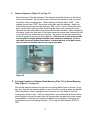
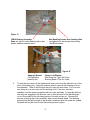
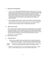
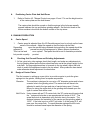
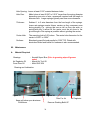
1OPERATION AND SERVICE MANUAL
for
MOYER 18 INCH CRUSH/DOWNFEED GRINDER MODEL 5-18-2VCD
February 1996 Revised February 2003
MOYER MANUFACTURING COMPANY, INC.
2862 W US HWY 20
ANGOLA, IN 46703
Mail - P.O. Box 422
FREMONT, IN 46737
Phone (260) 665-2363
Fax (260) 665-2393
MOYER PROCESS & CONTROL CO., INC.
P.O. BOX 935 - 6045 N. WAYNE STREET
FREMONT, IN 46737
Phone (260) 495-2405
Fax (260) 495-1290
READ SAFETY INSTRUCTIONS PRIOR TO SET UP AND OPERATING THE GRINDER
IMPORTANT OPERATIONAL NOTES
ONLY TURN OFF THE COMPUTER WHEN IT IS IN THE MAIN MENU. IF IT IS TURNED
OFF IN ANY OTHER MENU, THE HEAD POSITIONS WILL BE LOST.
When adjusting the carrier height using the jackscrew, back off the jack screw via the hand
wheel after the carrier is locked in place with the setscrew. Failure to lower the jackscrew
will cause an early failure of the jack. . The jack is not affixed to the shaft; hence it will
always raise the carrier. It never lowers the hub. Gravity lowers the carrier as the
jack is backed away from the carrier shaft hub. Turn the hand wheel clockwise to
raise the carrier. If the carrier does not go down when the hand wheel is backed away
from the shaft of the carrier plate-mounting hub, tap on the carrier to move it down.
DO NOT POUND THE CARRIER DOWN. IF IT MOVES SO HARD THAT A TAP WILL
NOT MAKE IT DROP, THE BORE OF THE CONE DRIVE AND THE SHAFT MUST BE
CLEANED. THE SHAFT WILL PULL UP AND OUT OF THE BORE FOR CLEANING.
1
Page
3
3
3
4
4-5
5-8
5
5-6
6
7-8
9
`
10-15
10
10-11
11-12
12
13-14
15
16
16
17
18
18
19
19
20-21
22
22
23
22
23
23
23-24
24-27
INDEX FOR MOYER 18” CRUSH GRINDER MODEL 5-18- 2V
Section
Description
Figures
I.
Receiving Machine
II.A
Uncrating Machine
II.B
Installation of Leveling Pads
1-2
II.C
Unblocking Grinding Heads
3
III.
Electrica, Air And Dust Collector
IV.
Safety Issues
IV.B.
Hazardous Voltages
IV.C.
Setup, Stone Change and Dressing
3
IV.C.3
Changing Stars
4,5,6,7
IV.D.
General Safety Issues & Machine Controls
8
V.
Power Tests
8,9,10
VI.
Run outs and Final Leveling
11 thru 23
VI. A.
Leveling The Machine Frame
11,12
VI.B.
Parallelism Between Top & Bottom Frame
13,14,15
Plates With Top And Bottom Motor Plates
VI.C.
Dresser Alignment
16
VI.D.
Parallelism Of Bottom Stone Mounting Plate
17
VI.E.
Setting Carrier Drive In Same Plane As Bottom 18 thru 21
Stone Mounting Plate
VI.F.
Sub Plate Alignment
22,23
VII.
Manual Controls
24 thru 32
VII.A.1
Carrier Adjustment Vertically
24
Note Warning On Jack Adjustment
VII.A.2
Spring Hold Down
25
VII.A.3
Head Position Using Hand Wheels
8
VII.A.4
Canting Top Head
26,27
VIII.
Mounting Grinding Wheel And Dressing
28 thru 32
VIII.A.
Changing And Mounting Stones
VIII.B.
Changing Star Cutters
VIII.C.
Dressing The Grinding Wheels
VIII.D.
Mounting Carrier Plate
IX.
Basic Setup Procedure
IX.A.
Positioning Stones
IX.B.
Positioning Carrier Plate And Hold Down
X.
Running Production
XI.
Design of Carrier Plates
XII.
Maintenance
33-37
1
2
I. Receiving
A.
Damage
Check the crates and machine for any signs of damage. If damaged, advise the
driver immediately that you suspect damage to the machine and note this fact on the
bill of lading. Call the shipper for instructions before unloading and uncrating.
II.
Uncrating and Locating The Machine
A.
Uncrating
Remove one of the plywood sides. Remove the top piece of plywood. The remaining
sides and the 2x4's can be removed together. Remove the four screws holding the
grinder to the skid. Two of the screws are on the front lip of the grinder under the
carrier. The other two screws are inside the base weldment. Remove the two back
access plates to remove the screws. The machine weighs approximately 2,700
pounds. Hence size the forklift accordingly.
B.
Installation of Leveling Pads (Figures1 and 2 on page 3)
After the machine is moved to its final location and before setting it down, the 4 round
leveling pads will need to be put under the machine. The leveling pads are shipped in
a box with other accessories. The pads are installed under the holes from which
the screws were removed in the step above. Holding the pads under the weldment,
push the machine screws with the jam nuts on top through the hole and screw into
the pads approximately 1". BLOCK THE MACHINE UP PRIOR TO HOLDING THE
PADS UNDER THE WELDMENT. DO NOT DEPEND UPON THE FORK LIFT
HOLDING THE MACHINE DURING THIS PROCEDURE.
Figure1
Figure 2
Leveling Pad At Front of Machine
Leveling Screw At Back Of Machine
3
C.
Unblocking the Grinding Heads (Figures 3,4 and 5 on page 4)
The top and bottom motor spindles are blocked for shipment. Remove the wood
blocks from beneath the bottom motor plate and between the top and bottom 18"
grinding wheel mounting plates. The spindle motors are moved via stepper motors
thru gearboxes. The gearboxes have clutches that should be loosened to move the
motor spindles. The clutch for the top spindle is located on the top of the machine in
the back. The clutch for the bottom can be accessed thru the panel on the computer
side of the machine. Raise the top spindle by turning the top hand wheel clockwise to
remove the wood blocks. After the wood blocks are removed between the grinding
wheel mounting plates, raise the bottom spindle by turning the lower hand wheel
clockwise.
Figure 3
Inner Guards
NEVER REMOVE
Wood Blocks
Figure 4
Clutch Shaft Top Spindle Motor
Figure 5
Clutch Shaft For Bottom Spindle Motor
4
III.
Electrical, Air and Dust Collector Hookup
A.
Electrical
Have a qualified electrician run electrical power to the disconnect making sure that
their is an earth ground and that wiring is in conformance with all local and national
codes. The machine requires 40 amps at 240 volts and 25 amps at 480 volts.
Electrical schematics are located in the enclosure.
B.
Compressed Air
The air regulator located on the right side of the machine as one faces the carrier
drive system must be connected to a minimum of 60 PSI air source. The air is for
opening and closing the spring drop out chute and operating the ground lengthmeasuring device if this option is purchased. This initial setting may have to be
modified after set up. Adjust the Moyer Exit Mounted Probe pressure depending up on
observed performance. The probe should move smoothly to measure the parts with a
low-pressure setting. It must have enough pressure to get to the measuring point but
should not come down with a lot of force.
C.
Dust Collector
For optimum dust collection and cooling, the unit should have at least 1020 CFM.
The dust collector outlet on the machine has a O.D. dimension of 8 inches.
IV.
Safety Considerations
A.
When The Grinder Arrives
Prior to operating the machine, please review the safety information with all
operators, setup personnel, and maintenance crew.
B.
Hazardous Voltages
1.
When installing the grinder, have a qualified electrician wire the power according to
all local and national codes, and you must be sure to provide a secure GROUND TO
EARTH, such as using a 4-wire hookup.
2.
Caution operators and maintenance personnel that hazardous voltages exist inside
the disconnect enclosure, the motors, the junction box in the base weldment,
Operator Console and motor terminals. The places containing electrical components
must not be uncover or serviced without DISCONNECTING ALL POWER first using
Company LOCK OUT PROCEEDURES.
5
C.
Setup, Stone Change, and Dressing Safety Issues
1.
Guards
Surrounding the stones are thick top and bottom inner guards. NEVER remove
these inner guards. (Reference Figure 3 on page 4)
2.
Grinding Stones
Insist that employees changing grinding stones: Inspect stones for ANY cracks or
defects before mounting. Be sure the stone is sitting flush onto its mounting plate.
Dowels MUST be used to ensure proper centering. Bolts MUST NOT stick into the
stone more than 3/8", but must have enough thread contact for proper mounting.
Do not force the bolts. They should be tight, but over tightening can crack the stone.
Refer to Grinding Wheel Supplier for proper torque. Please read the entire section
"Changing and mounting stones" in the "Setup and Tooling " chapter VIII. on page
19 to all employees performing this function.
3.
Dresser (Figures 4,5,6 and 7 on page 7)
Caution operators that before dressing the stones, they need to inspect the dresser
to make sure the stars are tight on the cutter bushing . The BB10 bearing assembly
with the stars should be tight to the dresser head but spin freely when rotated. The
BB10 bearing assembly is assembled to the dresser head by the hex bushing
screws and hex locking nuts. The dresser head must be tight on the dresser shaft.
The dresser unit must be held securely in the dresser mounting support. Stars
should be staggered. If the sharp points line up on stars, turn the stars over and put
back on the bearing assembly.
6
Figure 4
Figure 5
BB10 Bearing Assembly
Stars are tight on cutter bushing with cutter
spacer washers between stars.
Figure 6
Spanner Wrench
ForTightening
Bushing Nut
Mounting
Dresser Head
Hex Bushing Screws And Locking Nuts
are tightened to the dresser head using
the BB wrenches.
Figure 7
Cutter Lock Washer
After Stars Are Tight On Cutter
Bushing, Bend A Tab On Cutter
Lock Washer
7
Dresser Unit
Dresser
Support
Figure 8
Lock Handle
Swing Out Carrier
Hold Downs
Hand Wheel For
Raising / Lowering
Carrier
Panic Buttons
Hand Wheel For
Setting Hold Downs
D. General Safety Instructions (Figure 8 on page 8)
1. Front Guards
Prior to operating the grinder, insist that all guards are in place and bolted to the
machine. Ensure that the black lock handle that locks the front carrier swing plate is
always SCREWED IN TIGHT as this plate is part of the guard system. Insist that the
front top guard is moved down in front of the top wheel prior to running machine.
2. Safety Glasses
Insist that safety glasses be worn by all employees operating and loading the
grinder.
3.
Instructions to the Operator
Review the operation of the machine and make sure that employees know the
location and operation of the panic-stop buttons (on the console face and under the
sub plate).
Do not allow operators to load springs too close TO THE ENTRANCE HOLD DOWN
AREA, as their hand could be caught between the hold-down and carrier plate.
Insist that operators keep their fingers AWAY FROM THE DROPOUT AREA, as
8
they may be injured, or pinched between the carrier and side of the dropout.
Caution operators that while setting up and operating the Moyer Automatic Loading
equipment that they should not stick their fingers in between the nozzles and
carrier, near the positive stop or indexing pin.
Insist that operators do not stick anything into the grinding stones while the stones
are operating, do not lay tools on the carrier plate to be dragged inside the grinder,
and do not work on the machine until the stones have completely stopped.
Do not allow operators to load springs or work on the machine while wearing loose
clothing, very long hair, necklaces, bracelets, or rings as springs can catch on these
items and pull the operator into the grinding wheel area.
Warn operators and setup personnel that when adjusting the carrier in the vertical
position that the Jackscrew must be moved against the carrier drive hub. The
jackscrew is adjusted by rotating the jackscrew hand wheel clockwise. When the set
screw in the collar around the carrier drive hub is loosened the carrier can drop
immediately to the subplate unless the jack screw is against the carrier drive hub.
Figure 9
9
V.
Power Test
A.
Console (Figures 9 on Page 9)
When the power hookup is completed, test it by turning on console power, using the
selector switch marked “CPU” at the center right of the console face. The screen
should “come alive” and present you with the “Main Menu” of the CNC system. Use
the keypad’s down-arrow key to highlight “Crush grind” and press the ENTER key.
The “Crush” menu will appear, from which you then select “dial jog” or “dial run”
appearing on the bottom of the window. Confirm that this menu selection turns the
carrier hub motion on and off, and that the “dial speed” knob on the lower center of
the console regulates the speed. Also confirm that the “dial jog” knob above it allows
you to run the carrier backwards and forwards at half speed.
B.
Rotation
Caution - Prior to making this check, make sure that nothing is laying loose on either
of the grinding wheel mounting plates and that all protective guards are in place.
Using the start and stop button for the top and bottom spindles, jog each motor to
check rotation. The spindles and carrier should rotate counter-clockwise when
looking down from the top of the machine. As the drive rotation was set at the
factory, if the rotation is incorrect reverse two of the incoming power lines to the
disconnect switch.
C.
EMERGENCY STOP:
Pushing in this red mushroom push button stops the carrier and removes spindle
power, allowing the stones to coast to a stop position. To return the machine’s
functions, pull the button back out. There is a second emergency stop button mounted
to the front of the sub plate which works the same as the emergency stop button on the
console.
10
VI.
Run outs and Leveling
The next step is to check alignments and run outs of the major moving parts of this
machine. These checks require a machinist’s level, felt marker, and a good dial
indicator graduated in the thousandths of inch.
A.
Leveling the Machine Frame (Figure 10 and 11 on page 11)
Unlock and swing out the carrier assembly to gain access to the top plate of the base
weldment. Position a machine level on this frame plate. Adjust the four bolts in the
leveling pads until the machine is level in the side-to-side and front to back directions.
Tighten the jam nuts on the levelers to keep this setting. It may be necessary to go thru
this procedure several times to get the machine level in both planes. It is necessary to
verify that the machine is still level after the nuts are tightened. The level of the
machine may change when the nuts are tightened.
Figure 10
B.
Figure 11
Parallelism between Top And Bottom Frame Plates And Top And Bottom Motor
Plates (Figure 12,13 and 14on page 12)
With the swing out carrier open and with the outer guards removed, use a height gage
or calipers to check the parallelism between the bottom frame plate and the bottom
(moveable) motor plate at the three ball screw locations. If the readings at the ball
screws differ by more than 0.010" remove the master link of the bottom chain
connecting the three screws and adjust them independently to achieve a parallelism
of 0.010" or less. Repeat this process between the top frame plate and the top motor
plate. Do not reassemble the chain until later in the process of leveling the machine.
Hints: Adjust one ball screw at a time then check for results. If you move more
than one ball screw at a time, it is difficult figuring out which ball screw must be
moved to get the heads parallel with the frame plates. Prior to removing the chain
rotate the ball screws such that the connectors for the chains are on the sprockets.
Check to see if each of the screws can be rotated a slight amount with the same
amount of resistance. If one or more screws are tighter than others, it means that one
of the screws was moved an excessive amount one-way or the other. Correct this
condition prior to going to the next step. Set the parallelism as close as possible
without binding the ball screws.
11
Figure 13 Outer Guard Removed
Top Frame Plate
Bottom Motor Plate
Top Motor Plate
Bottom Frame Plate
Figure 14 Using Height Gage
Figure 15 Chain and Sprocket For Bottom
Spindle
12
C.
Dresser Alignment (Figure 16 on Page 13)
Mount the base of the dial indicator to the dresser head with the tip onto the bottom
stone mounting plate. Set the dial to zero, and move the dresser in and out across
the bottom stone mounting plate. These readings should be within 0.006”. If the
reading is more than 0.006”, the bottom motor plate must be adjusted. Adjust the
three bottom ball screws until the reading is .006” or less. Prior to putting the chain
back onto the ball screw sprockets make sure that each of the screws turn freely.
Reinstall the chain and make a final check with the chain installed. When reinstalling
the chains, make sure that each of the chains have the excess slack removed but are
not so tight that the screws are put on a bind. The tension on the chain connecting
the three screws is set using a chain tightener. Check to see if each of the screws
can be rotated a slight amount with the same amount of resistance. If one or
more ball screws are tighter than others, it means that one of the ball screws
was moved an excessive amount one-way or the other.
Figure 16
D. Checking Parallelism of Bottom Stone Mounting Plate To Top Stone Mounting
Plate (Figure 17 on page 14)
Set the dial indicator between the two stone mounting plates (base on bottom, tip on
top) and rotate the two plates together to see if the stone mounting plates are parallel.
Orient the plates so their locating pins are in line then turn the plates so that the
locating pins remain in line. If the top stone plate is not parallel with the bottom stone
mounting plate, remove the chain from the top sprockets and adjust the three screws
independently so that the stone plates are slightly closer together at the spring exit
point than they are at the spring entrance. Try to keep the cant between 0.003" to
.008"
13
Figure 17
.
Locating pins
E. Setting the Carrier Drive In The Same Plane As The Bottom Stone Mounting Plate
1.
Marking Run Out of Bottom Grinding Stone Mounting Plate
(Figure 18 on page 14)
Place a dial indicator with its base on the bottom motor plate and its tip near the
outside edge of the bottom stone mounting plate. On the plate mark the run out
(plus or minus from zero) every 3" around its circumference. The run outs should
not exceed 0.008". If the run out exceeds the .008" contact Moyer Manufacturing
Company, Inc.
2.
Run Out of Carrier Hub (Figure 19 on page 14)
Put the indicator base on the sub plate and the tip onto the shoulder of the carrier
hub. Rotate the hub using the "Dial Jog" and mark the run out of the hub, which
should not exceed 0.002". If this is not within +/- .002" contact Moyer Manufacturing
Company, Inc. for assistance.
Figure 18
Figure 19
14
3.
Checking The Carrier Drive (Figures 20 & 21 on page 15)
Rotate the bottom stone mounting plate so that its previously marked run out
readings have the same value at the spring entrance and exit points. Set the
indicator base onto the carrier hub and the tip of the indicator onto the spring
entrance point on the bottom stone mounting plate. Rotate the carrier hub
using the
"Dial Jog" to sweep the indicator across the stone mounting plate in the
path that
the springs will go thru the grinder. The reading should not vary more
than 0.006"
progressively thru the path. To check the parallelism toward the back
of the machine, use a precision straight edge with precision blocks. This is a twoman operation. One person holds the straight edge tight against the carrier hub shaft
while the 2nd person checks the back position using shims. If the readings vary
more than .006”, the cone drive must be shimmed.
Figure 20
Figure 21
Note: These two pictures are from a different machine. However the procedure is the
same.
4.
Adjusting The Carrier Drive
If the check performed in Figure 21 is off, the gearbox must be shimmed to set the
the front to back position. Loosen the bolts holding the large carrier gearbox to the
swing plate. Adjust the gearbox using shims under the feet of the gearbox and
retighten. Repeat this procedure until the 0.006" is achieved. If the check performed
in Figure 20 is off, there is enough room around the bolts holding the gearbox to
twist the gearbox so that the entrance and exit side of the grinding plate are within
.006" with the cone drive.
15
F.
Sub plate Alignment (Figures 22 &23 on page 16)
Mount a carrier onto the carrier hub. Using shim stock check the space between the
carrier and the sub plate at several places around the carrier. Adjust the sub plate to
get an equal distance between the carrier and the sub plate. The sub plate is adjusted
by the turnbuckles under the front of the sub plate and the slotted angle blocks
supporting the sub plate behind the carrier swing plate.
Figure 22
Figure 23
G. Further Setup
The chapter,"Setup and Tooling For A New Job", provides the instructions for safely
mounting and dressing stones, mounting the carrier plate and other topics in setting up
a new job.
16
VII. Manual Controls
A. Manual Adjustments Available
1. Carrier Adjustment Vertically (Figure 24 on page 16)
To adjust the carrier up and down, the setscrew in the collar on the cone drive is
loosened using the long T-handle provided. Use the console's dial jog switch to
rotate the carrier until the setscrew can be reached using the long T-handle. Note
turn the speed pot all the way counter-clockwise so that the dial will not move fast.
Turn the speed pot up slowly or clockwise until the carrier starts to move slowly.
After the setscrew is loosened, the adjusting hand wheel located at the front of the
machine under the carrier plate is used to raise the carrier plate. This hand wheel is
connected to a jack under the shaft of the carrier plate mounting hub. The jack is not
affixed to the shaft; hence it will always raise the carrier. It never lowers the shaft.
Gravity lowers the carrier as the jack is backed away from the carrier shaft hub. Turn
the hand wheel clockwise to raise the carrier. If the carrier does not go down when
the hand wheel is backed away from the shaft of the carrier plate mounting hub, tap
on the carrier to move it down. DO NOT POUND THE CARRIER DOWN. IF IT
MOVES SO HARD THAT A TAP WILL NOT MAKE IT DROP, THE BORE OF THE
CONE DRIVE AND THE SHAFT MUST BE CLEANED. THE SHAFT WILL PULL UP
AND OUT OF THE BORE FOR CLEANING.
Warn operators and setup personnel not to have their hands under the carrier when
adjusting the height. When the setscrew in the collar around the carrier drive hub is
loosened, the carrier can drop immediately to the sub plate. To prevent this from
happening, adjust the jackscrew so that there is pressure on the screw. When
lowering the carrier, slowly back down the screw so that the carrier slowly drops
toward the sub plate. When the carrier is at the correct height, use the long T-handle
and tighten the setscrew to lock the carrier in position. To prevent damage to the
jack, back off the jack so that it is not touching the shaft of the carrier plate
mounting hub prior to running production. This adjustment is required to
equalize the amount of spring length sticking above and below the carrier’s
thickness.
Figure 24
17
2.
Entry and Exit Hold downs (Figure 8 on page 8 and Figure 25 on page 17)
The entry and exit hold-downs are fastened to the front plate. The heights of both
hold-downs are adjusted together using the 4" hand wheel on the front of the plate.
Set the entry hold down so that the bottom of the hold down is flush with the top
grinding wheel. The exit hold-down is set at the factory slightly higher than the entry
hold-down. The hold-downs can be moved relative to the front plate by adjusting the
mounting screws.
The entry hold-down alignment is critical in the crush mode. The springs should just
slide between the two grinding wheels. If the hold-down is too high, the springs will
hit the edge of the grinding wheel, which will radius the edge of the wheel. If the
hold- down is too low, the springs will compress too much and the end coils opposite
the tips will compress too much which will adversely affect squareness, wheel life
and time between dresses.
Figure 25
Grinding Wheel.
Hold- Down
The grinding wheel is not mounted to the steel mounting plate.
The steel plate shows the grinding wheel location in relation to the entry hold-down.
18
3.
Head Position Hand Wheels (Figure 8 on page 8)
The two hand wheels on the left side of the grinder are for manually adjusting the
grinding spindles. Turning the top hand wheel CLOCKWISE moves the top spindle
UP. Turning the bottom hand wheel CLOCKWISE moves the botton spindle down.
One rotation of the hand wheels move the spindles .050".
4.
Canting Top Head (Figures 26 & 27 on page 18)
Remove the two panels, one by the dresser and one by the exhaust pipe to gain
access to the top motor spindle. Loosen the four bolts holding the top motor to the
top motor plate and lift up the motor using the jack bolt in the mounting flange of
the motor. Insert three shims at 90 degrees to the dresser. Refer to the chart on
page 18 for shim thickness. Position two shims ½ the thickness of the first shim 90
degrees to the left and right of the first shim. Let the motor down on the motor plate
using the jack bolt then tighten the four bolts holding the top motor to the top motor
plate. Tighten one bolt then move diagonally across the motor and tighten that bolt.
Continue moving from bolt to bolt in this X pattern until all bolts are tight. To go
back to a parallel grind reverse this process. If the first shim is positioned 90
degrees to the dresser, the shims do not have to be removed before dressing the
wheels. A starting point for canting is one half a wire size.
THICKNESS OF SHIMS
Machine
Desired Amt of Cant
Shim Thickness
18'
.050"
.100" Or Twice The Amount of Cant
30"
.050"
.075" Or A 1 to 1.5 Relationship
36"
.050"
.090" Or A 1 to 1.8 Relationship
Figure 26
Access Panel
Figure 27 Two of the three shims Jack Bolt
19
VIII. Mounting Grinding Wheels And Dressing
A.
Changing and Mounting Stones
1. Loosen the black handle under the sub plate and swing the carrier out to have
access to the stone mounting plates. Using the hand wheel, raise the front
guard
plate. Lower the bottom stone mounting plate to a position that the grinding
wheel
can be put on the bottom grinding wheel mounting plate.
2. Clean the bottom stone mounting plate by wiping it off with your bare hand until all
the grit is removed. Rotate the bottom stone mounting plate so that one of the
dowels is in an area that can be easily seen. Mark the outside of the bottom
stone
mounting plate for the dowel location.
3. Clean the mounting surface of the grinding wheel making sure that the aligning
holes are free of any foreign material. Mark the outside of the grinding wheel
showing the dowel hole location. Slide the grinding wheel across the stone
mounting plate so that the aligning holes in the grinding wheel and the
dowels in the
stone mounting plate line up. Use a screw driver to raise the wheel
up so that it
rests on the dowels. When the dowels and the holes in the stone
mounting plate l
ine up, the grinding wheel will drop onto the stone mounting plate.
Bolt the wheel
into place.
4. Inspect stones for ANY Cracks or Defects before mounting. Be sure the stone is
sitting flush onto its plate. Dowels MUST be used to ensure proper centering.
Using
the 3/8-16 SHCS bolts provided for the machine, bolt the grinding wheels to
the
grinding wheel mounting plate. BOLTS MUST NOT STICK INTO THE
GRINDING
WHEELS MORE THAN 3/8" BUT HAVE ENOUGH THREAD
CONTACT TO HOLD
THE WHEELS ONTO THE STEEL MOUNTING PLATES.
Do not force the bolts.
They should be tight, but over tightening will crack the
stone. Reference the
grinding wheel supplier for the correct torque.
5. Lay the wheel for the top grinding wheel mounting plate on top of the bottom
grinding wheel. Lower the top stone mounting plate making sure that the
alignment
holes in the grinding wheel line up with the dowels in the stone mounting
plate.
Don't bring the top head down so that the dowels completely enter the
grinding
wheel alignment holes. Use a small pry bar and lift the top wheel up
and start
several of the grinding wheel mounting bolts that are next to the
dowel. Rotate the
wheels so that another set of bolts can be started into the
grinding wheel next to
the dowel located 180 degrees away from the first
dowel. Insert the remaining bolts
and tighten.
6. When the stones are installed, be sure all tools, wood, and other foreign objects are
removed from the grinder interior. Move the grinding wheel so they are close, but
do not touch the dressing stars. CAUTION- WITH THE FRONT PLATE UP FOR
CHANGING STONES, THE ENTRANCE AND THE EXIT HOLD DOWNS ARE
CLOSE TO HITTING THE STONE MOUNTING PLATE. THE JACK THAT
MOVES
THE HOLD DOWNS CAN BE DAMAGED IF THE HOLD DOWNS HIT
THE STONE
MOUNT PLATE. Move the hold downs down prior to bringing the top
head down.
20
B.
Changing Star Cutters (Figures 28, 29, 30, on page 20 Figures 31 & 32 on
page 21)
Reference page 6 under Section IV. Safety
1.
The stars can be changed inside the machine as shown in figure 28 or the dresser
shaft can be removed from the dresser block as shown in figures 29 and 30. The
dresser is heavy use caution when handling.
Figure 28 Changing stars inside machine
Figure 29 Dresser shaft removed
Figure 30 Removing dresser
2.
Loosen the two hex locking nuts and back off the bushing screw. After the outside
bushing screw is removed from the dresser head, the cutter assembly BB10 can be
removed for replacing stars. We recommend Desmond Sharp Tooth Cutters 17-A.
21
22
Figure 31
BB10 Bearing Assembly
Stars are tight on cutter bushing with cutter
spacer washers between stars.
Hex Bushing Screws And Locking Nuts
are tightened to the dresser head using
the BB wrenches.
Figure 32
Spanner Wrench
ForTightening
Bushing Nut
3.
Cutter Lock Washer
After Stars Are Tight On Cutter
Bushing Bend A Tab On Cutter
To take the worn stars off and replace with new ones, bend the tab back out of the
slot in the bushing nut. Using the spanner wrench, remove the bushing nut from
the assembly. Take off all the worn stars but save the worn stars. Put on a new
star then put on a worn star until the bushing is full. If no worn stars are
available, use the spacers supplied with the cutter assembly. To align the teeth so
that they are staggered, flip the stars over so that the tooth of the star being put
on is in the middle of the two sharp points of the star just put on. Reverse the
process of putting the cutter assembly back on the dresser head. The bushing
screw should be tight enough to feel a small resistance when the stars are rotated.
Reinstall the two jam nuts to hold the bushing screw in place.
23
C.
Dressing The Grinding Wheels
1.
Caution operators that before dressing the stones, they need to inspect the dresser
to make sure the stars are tight on the cutter bushing . The BB10 bearing assembly
with the stars should be tight to the dresser head but spin freely when rotated. The
BB10 bearing assembly is assembled to the dresser head by the hex bushing
screws and hex locking nuts. The dresser head must be tight on the dresser shaft.
The dresser unit must be held securely in the dresser mounting support. Stars
should be staggered. If points line up on stars, turn the star over and put on
bearing assembly.
2.
Move the grinding wheels closer to the teeth of the dresser by moving the dresser
into the grinding area until contact is made. Start the motors and dress both heads
at the same time or individually. While dressing slowly move the top and bottom
wheel into the dresser as the dresser is moved between the wheels.
D.
Mounting Carrier Plate
Prior to mounting the carrier plate, clean the two mounting surfaces to ensure that the
two surfaces are clean. Any dirt on these surfaces can make the spring carrier plate
run through the grinder on such a tilt that the springs may not grind square. After this
cleaning, set the carrier gently onto the carrier plate mounting hub. If fixtures or tubes
are used, make sure that they are set at the same height and that they are set
perpendicular to the grinding wheels.
IX.
Basic Setup Procedure
A.
Positioning Stones
1.
The bottom stone’s height should be positioned right at or a slight bit below the
entrance edge of the sub plate. The exit side of the sub plate should be slightly
lower than the grinding wheel. With this setting the springs will slide easily
between
the stones, to prevent chamfering the stone or the springs. At the exit, the
springs
should not get caught against the sub plate upon leaving the stones.
2.
Bring the top grinding wheel down to the estimated grind length position. A gage
block or a ground sample spring may be used to determine this position.
24
Positioning Carrier Plate And Hold Down
B.
1.
Refer to Section VII. "Manual Controls on pages 16 and 17 to set the height and on
of the carrier plate and the hold downs.
The carrier plate should be moved so that the springs in the holes are equally
spaced between the top and bottom grinding wheels. Set the hold down so the
bottom surface is level with the bottom surface of the top stone.
X. RUNNING PRODUCTION
A.
Carrier Speed
1.
Carrier speed is adjusted from 0 to 60 Revolutions-per-hour by a knob on the lower
center of the console. Adjust the speed so that the holes can be filled
Depending
upon the results being obtained during grinding, the speed should be
adjusted to
prevent burning the springs and to ensure proper equalization.
This is a trial and
error system. The speed should be set to maximize production
but provide a quality
product.
B.
Checking first Ground Pieces and Grinding Adjustments
1. At first, grind only a few springs, check their length, and make any adjustments to
the top grinding wheel as the bottom wheel has been set at the proper height for the
sub plate. If a large adjustment has to be made to the top wheel, adjust the hold
down to match the adjustment made to the top wheel. After production has started
make alternate wheel adjustment for wheel wear.
XI.
Design of Carrier Plates
The first concern in setting up a new job is to provide a carrier to push the given
springs into the grinder, holding them as square as possible.
Diameter:
The machine is designed to use up to a 30” diameter carrier.and to have
a center hole in the grinding stone. The center hole will have to be
adjusted to match the type and size of carrier being used. Contact
Moyer for sizing the center hole in the grinding stone based upon the
type of carriers that will be used.
Bollt Circle: Using stones with an 8” ID center hole, the 30" carrier would require that
the outermost holes be on an approximate bolt circle of 28.5". The
actual bolt circle is dependent upon the hole size in the carrier. The
distance between the centerline of the carrier and the grinding wheel is
18.25". If the hole is put on a 28.5" bolt circle ½ of the spring O.D. will
pass over the center hole. For small diameter springs the bolt circle
should be reduced based upon the diameter of the spring.
25
Hole Spacing: Leave at least 0.125” material between holes.
Hole Size:
Make holes at least 0.006” to 0.015” larger than the spring diameter
depending upon size of wire, squareness required and the length to
diameter ratio. Longer springs typically can have more clearance.
Thickness:
Subtract 1 to 2 wire diameters from the free length of the springs.
Lower rate springs require thinner carriers as they compress more
during grinding. For springs that are as tall as they are wide, or
springs with only ½ active coil, the carrier must be as close to the
ground length of the spring as possible without grinding the carrier.
Center Hole:
The mounting hub is 5.00 inches. The center hole dimension for the
carrier is 5.002" to 5.004".
Surfaces:
Blanchard ground flat and parallel to 0.002” TIR. Plated with
electroless Nickel and baked for hardness is also recommended.
XII. Maintenance
A.
Material Required
Bearings
Air Regulator Oil
Cone Drive Oil
- Kendall Super Blue (Prior to greasing wipe off grease
zerks)
- Marvel Air Tool Oil
- Mobil SHC 634
Cleaning and Lubrication
Figure 33
Figure 34
Filter For Air
Keep grit below spun aluminum
Conditioner
Remove Grinding Build UP
26
Air Regulator
1.
Daily
General - clean off the machine each day to remove grit. If using air, maintain a low
pressure so that grit is not forced into working components of the machine or your
eyes.
Air Regulators/Oilers - should be filled with oil suitable for pneumatic devices and
their seals. Commonly available “Marvel Mystery Oil” is good for this. Push in the pin
at the bottom of the regulator to drain away all accumulated water, and change the
filter if it’s getting dirty. Figure 34
2.
Weekly
Cleaning - Every time that grinding wheels are changed. It is very important to clean
under the bottom stone mounting plate. KEEP THE DUST BELOW THE SPUN
ALUMINUM HOUSING AROUND THE STONE MOUNTING HUB. Also check the
exhaust opening for build up of hard grinding swarth and remove. Figure 33
Blower If Purchased- Check filter and replace if dirty. This blower pumps air thru the
spindles. The blower can be damaged if any large particles get into the blower.
NEVER FORCE THE CARRIER UP OR DOWN. If the carrier moves hard, the Cone
drive shaft must be removed. Loosen the set screw holding the Cone drive shaft to
allow lifting the Cone shaft up and out of the bore in the Cone Drive. Some models
have a bellows attached to the Cone Shaft. Remove the hose clamp on the bellows
prior to pulling the shaft out. Clean the shaft very good as the slightest amount of grit
can make the Cone shaft move up and down hard.
3.
Every Month.
Rotary Union - If the grinder is equipped with a high velocity pump for pumping air
thru the spindles Grease the rotary unions on the top and bottom
spindle motors. Give each zerk 2 to 3 pumps of Alvania 2 grease or
other compatible qreases.
4.
Every 3 Months
Cone Drive - A zerk is provided to grease the top bearing of the Cone Drive. The
zerk is located under the sub plate on the hold down side of the machine. Also clean
around the boot where the drive shaft for the carrier goes into the hollow bore of the
cone. Replace the boot if it is torn. This is important. If grit gets onto the drive shaft,
the drive shaft will become stuck in the hollow bore and will not adjust the carrier up
and down easily. (Refer Figure 35 on page 26)
27
Figure 36
Zerk For Greasing
Oil Level
Top Bearing
5.
Keep Clean
Semi-annually
General Cleaning & Inspection - The outer guards may be removed to clean around
the bellows, exhaust, and dresser area. Check all bellows for any holes and replace
as needed.
Flange Bearings - Grease the six ball screw flange bearings (3) top and (3) bottom
with two pumps of grease
Cone Drive Seals - Clean the top of the Cone Drive so that any grit laying on the top
seal will be removed.
6.
Annually
Carrier Gearbox - check oil level in the elbow provided and add Mobil SHC synthetic
bearing and gear oil.
Continued on page 27
28
Ball Screws and Nuts - Remove the hose clamps around the top and bottom bellows
covering the three top and three bottom ballscrews. Using an oiler put a mixture of
50% STP and 50% Kendall Super Blue Grease at the top of each ball screw. Prior to
reinstalling the bellows, clean off any oil off the surfaces of the bellows mount. This is
important for reassembling the hose clamps around the bellows. (Refer To Figure 37
on page 27)
Roller chains - should receive brushing to remove any grit.
Figure 37
Roller Chain Top Head
Two of the Ball Screws For Top & Bottom Heads
29
30