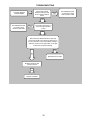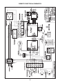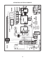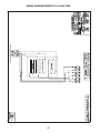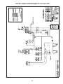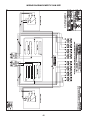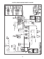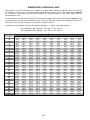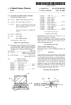
1
GRILLS MODEL MWE-9501 MODEL MWEH-9501 MODEL MWEF-9501 MODEL MWEL-9501 MODEL MWER-9501 MODEL MWE-9801 SERVICE MANUAL MANUFACTURED EXCLUSIVELY FOR McDONALD'S BY GARLAND COMMERCIAL INDUSTRIES, INC. 185 EAST SOUTH STREET FREELAND, PENNSYLVANIA 18224 TOLL FREE: (800) 446-8367 PHONE: (570) 636-1000 FAX: (570) 636-9874 E-mail: [email protected] NOTE: This manual pertains to all grill models listed above. The reader/operator must interpret its contents to applicable needs. However, if there is any question of interpretation of any literature pertaining to Garland grills, please contact our Customer Service Department at one of the phone numbers listed above. WARNING: IMPROPER INSTALLATION, ADJUSTMENT, ALTERATION, SERVICE OR MAINTENANCE CAN CAUSE PROPERTY DAMAGE, INJURY OR DEATH. READ THE INSTALLATION, OPERATING AND MAINTENANCE INSTRUCTIONS THOROUGHLY BEFORE INSTALLING OR SERVICING THIS EQUIPMENT. PLEASE READ ALL SECTIONS OF THIS MANUAL AND RETAIN FOR FUTURE REFERENCE. CAUTION: THIS EQUIPMENT MUST ONLY BE OPERATED UNDER AN APPROVED HOOD SYSTEM THIS EQUIPMENT “MUST” BE INSTALLED AND COMMISSIONED BY A PROFESSIONAL FACTORY TRAINED TECHNICIAN Part # 1382687 Rev. 4 Domestic / International Printed in U.S.A. (03/99) TABLE OF CONTENTS WARRANTY.................................................................................................................................................................................. 4 INTRODUCTION .......................................................................................................................................................................... 4 SHIPPING DAMAGE CLAIM PROCEDURE........................................................................................................................... 4 SAFETY .......................................................................................................................................................................................... 4 SPECIFICATIONS ........................................................................................................................................................................ 6 FULL-SIZE GRILL MODEL MWE-9501.............................................................................................................................. 6 HALF-SIZE GRILL MODEL MWEH-9501 .......................................................................................................................... 7 FULL-SIZE FLAT GRILL MODEL MWEF-9501................................................................................................................ 8 HALF-SIZE FLAT GRILL MODEL MWEFH-9501 ............................................................................................................ 9 HALF & HALF GRILL MODEL MWEL-9501................................................................................................................... 10 HALF & HALF GRILL MODEL MWER-9501 .................................................................................................................. 11 SLIM GRILL MODEL MWE-9801....................................................................................................................................... 12 RELEASE MATERIAL INSTALLATION ............................................................................................................................... 13 INSTALLATION ......................................................................................................................................................................... 14 PLATEN ZEROING .................................................................................................................................................................... 15 CLAMSHELL GRILL CONTROLS.......................................................................................................................................... 16 DESCRIPTION OF GRILL CONTROLS ............................................................................................................................ 17 The Master Power (Start (On)-Stop (Off)) Switch:............................................................................................................. 17 Indicator Lights: .................................................................................................................................................................. 17 Up Arrow Button - Two Functions: .................................................................................................................................... 17 Right Arrow Button - Two Functions: ................................................................................................................................ 17 Program Mode Button - Two Functions:............................................................................................................................ 17 Menu Button - Two Functions:........................................................................................................................................... 17 Temperature / Function Button - Two Functions: ............................................................................................................. 17 Standby Button - (Black):.................................................................................................................................................... 17 Cancel/Raise Platen Button - (Green): ............................................................................................................................... 17 HOW TO - NORMAL OPERATING MODES .................................................................................................................... 18 To Cook in Clam Grill Mode:.............................................................................................................................................. 18 To Cook in Flat Grill Mode:................................................................................................................................................ 18 Standby Mode: ..................................................................................................................................................................... 18 EXIT the Standby Mode: ..................................................................................................................................................... 18 To Display the Current Temperatures: ............................................................................................................................... 19 To View Settings for a Menu Item: ..................................................................................................................................... 19 To Clean the Grill: ............................................................................................................................................................... 19 Breakfast to Lunch Transition: ........................................................................................................................................... 19 PROGRAM LOGIC CHART ..................................................................................................................................................... 20 HOW TO - PROGRAM MODES ............................................................................................................................................... 21 SYSTEM SETUP ..................................................................................................................................................................... 21 To Display Temperatures in ºF or ºC: ................................................................................................................................. 21 To - Change the Speaker Volume, (High/Low): ................................................................................................................. 21 To Change the Gap Calibration: ......................................................................................................................................... 21 To Enable Hold Feature: (Chip Ver. 3.20 >): .................................................................................................................... 21 MENU ITEMS ......................................................................................................................................................................... 21 To Add or Delete A Menu Item: .......................................................................................................................................... 21 To Change Remove Time: ................................................................................................................................................... 22 To Change Alarm Auto / Manual: ...................................................................................................................................... 22 2 To Change Upper Platen Temperature:.............................................................................................................................. 22 To Change Griddle Temperature: ....................................................................................................................................... 22 To Change the Gap Setting: ................................................................................................................................................ 23 To Add/Program a Optional Menu Clam: .......................................................................................................................... 23 To Add/Program Optional Menu Flat: ............................................................................................................................... 24 To Add/Program High Limit Grill: ..................................................................................................................................... 24 To Add/Program High Limit Platen: .................................................................................................................................. 25 CALIBRATION ........................................................................................................................................................................... 26 CLEANING AND MAINTENANCE ......................................................................................................................................... 27 CLEANING AFTER EACH RUN OF PRODUCT:............................................................................................................. 28 TROUBLESHOOTING............................................................................................................................................................... 28 TO RESET TO FACTORY DEFAULTS: ............................................................................................................................ 28 ERROR MESSAGES:............................................................................................................................................................. 28 DOMESTIC ELECTRICAL SCHEMATICS ........................................................................................................................... 38 INTERNATIONAL ELECTRICAL SCHEMATICS ............................................................................................................... 39 DOMESTIC WIRING DIAGRAMS .......................................................................................................................................... 40 WIRING DIAGRAM DOMESTIC FULL SIZE .................................................................................................................. 40 CONTROL WIRING DIAGRAM DOMESTIC FULL SIZE ............................................................................................. 41 WIRING DIAGRAM DOMESTIC HALF SIZE.................................................................................................................. 42 CONTROL WIRING DIAGRAM DOMESTIC HALF SIZE............................................................................................. 43 WIRING DIAGRAM DOMESTIC FLAT GRILL .............................................................................................................. 44 CONTROL WIRING DIAGRAM DOMESTIC FLAT FULL SIZE.................................................................................. 45 WIRING DIAGRAM DOMESTIC FLAT HALF SIZE ...................................................................................................... 46 CONTROL WIRING DIAGRAM DOMESTIC FLAT HALF SIZE ................................................................................. 47 WIRING DIAGRAM DOMESTIC SLIM SIZE................................................................................................................... 48 CONTROL WIRING DIAGRAM DOMESTIC SLIM SIZE.............................................................................................. 49 WIRING DIAGRAM DOMESTIC HALF & HALF (LEFT SIDE) ................................................................................... 50 CONTROL WIRING DIAGRAM DOMESTIC HALF & HALF (LEFT SIDE) .............................................................. 51 WIRING DIAGRAM DOMESTIC HALF & HALF (RIGHT SIDE) ................................................................................ 52 CONTROL WIRING DIAGRAM DOMESTIC HALF & HALF (RIGHT SIDE) ........................................................... 53 INTERNATIONAL WIRING DIAGRAMS .............................................................................................................................. 54 WIRING DIAGRAM INTERNATIONAL FULL SIZE...................................................................................................... 54 CONTROL WIRING DIAGRAM INTERNATIONAL FULL SIZE.................................................................................55 WIRING DIAGRAM INTERNATIONAL COUNTRY SPECIFIC FULL SIZE ............................................................. 56 CONTROL WIRING DIAGRAM INTERNATIONAL COUNTRY SPECIFIC FULL SIZE ........................................ 57 WIRING DIAGRAM CANADA FULL SIZE....................................................................................................................... 57 WIRING DIAGRAM CANADA FULL SIZE....................................................................................................................... 58 CONTROL WIRING DIAGRAM CANADA FULL SIZE.................................................................................................. 59 WIRING DIAGRAM INTERNATIONAL HALF SIZE ..................................................................................................... 60 CONTROL WIRING DIAGRAM INTERNATIONAL HALF SIZE ................................................................................ 61 WIRING DIAGRAM INTERNATIONAL FULL SIZE FLAT .......................................................................................... 62 CONTROL WIRING INTERNATIONAL FULL SIZE FLAT .......................................................................................... 63 WIRING DIAGRAMS INTERNATIONAL COUNTRY SPECIFIC FULL SIZE FLAT................................................ 64 CONTROL WIRING DIAGRAM INTERNATIONAL COUNTRY SPECIFIC FULL SIZE FLAT ............................. 65 WIRING DIAGRAM INTERNATIONAL SLIM GRILL................................................................................................... 66 CONTROL WIRING INTERNATIONAL SLIM GRILL .................................................................................................. 67 TEMPERATURE CONVERSION CHART.............................................................................................................................. 68 3 meets all of McDonald's efficiency, and cleanliness. WARRANTY This warranty covers defects in material workmanship under normal use providing that: standards for safety, and SHIPPING DAMAGE CLAIM PROCEDURE Please note that the Garland equipment was carefully inspected and packed by skilled personnel before leaving the factory. The transportation company assumes full responsibility for safe delivery upon acceptance of the equipment. a) the equipment has not been accidentally or intentionally damaged, altered or misused. b) the equipment is properly installed, adjusted, operated and maintained in accordance with national and local codes and in accordance with the installation instructions provided with this product. What to do if the equipment arrives damaged: 1. File a claim immediately regardless of the extent of damage. c) the warranty serial number affixed to the appliance by us has not been defaced, obliterated or removed. 2. Be sure to note, "visible loss or damage," on the freight bill or express receipt and have the person making the delivery sign it. d) an acceptable report for any claim under this warranty is supplied to us. The equipment warranty coverage remains in force for one (1) year (parts and labor) from the date the equipment is put into operation and two (2) years (parts only) for the microprocessor controller, motor speed controller and upper platen (aluminum casting and shroud). 3. Concealed loss or damage: if damage is unnoticed until the equipment is unpacked, notify the freight company immediately, (within 15 days), and file a concealed damage claim. The Garland Group agrees to repair or replace, at it's option, any part that proves to be defective in material or workmanship at no charge for the part or normal labor. Always follow these safety precautions when operating the clamshell grill. SAFETY This grill must only be operated by persons who have been given adequate training. We assume no responsibility for installation, adjustments, diagnosis, or normal maintenance such as: lubrication of springs or valves. We exclude failures caused by erratic voltage or gas supplies. We assume no responsibility for travel costs beyond 100 miles round trip, travel other than overland, and overtime costs of repair. We exclude broken glass, paint and porcelain finish, surface rust, gasket material, ceramic material, light bulbs and fuses from normal coverage. We exclude damage or dysfunction caused by fire, flood, and like "Acts of God" that are beyond the control of The Garland Group. CAUTION: THIS EQUIPMENT MUST ONLY BE OPERATED UNDER AN APPROVED HOOD SYSTEM. DO NOT OPERATE THE GRILL UNLESS IT HAS BEEN COMMISSIONED (START-UP) BY A FACTORY AUTHORIZED SERVICE CENTER. DO NOT operate the grill without reading this operation manual. The Garland Group’s liability on a claim of warranty shall not exceed the price of the material and/or service, which caused the claim. This warranty is limited and is in lieu of all other warranties, expressed or implied. The Garland Group, our employees, or our agents shall not be held liable for any claims of personal injury or consequential damage or loss. This warranty gives you specific legal rights, and you may have other rights which vary from state to state. DO NOT operate the clamshell grill unless it has been properly installed and grounded. DO NOT operate the clamshell grill unless all service and access panels are in place and fastened properly. The Garland clamshell grill is a semi-automatic cooking appliance. The upper platen is lowered Automatically, following the manual, two-handed initiation of the cooking cycle, and the upper platen is raised automatically upon completion of the cooking cycle. INTRODUCTION The Garland clamshell grill, manufactured exclusively for McDonald's, provides a method for efficient twosided cooking, while accommodating a variety of products. The unit will also serve as a flat grill, and 4 Communication Standard, (HCS) manual for the appropriate Material Safety Data Sheet(s), (MSDS). When two sided cooking, the area between the upper platen and the griddle plate should be regarded as a “danger zone”. During two sided cooking the operator must not be within this danger zone. When used as a flat grill, then this area is no longer a danger zone, the platens do not move. WARNING: After turning the master power switch to the START position, the grill will go through an initialization process. If the upper platens are in the lowered position they will return to their raised upper position. This movement takes approximately 8 seconds. For whatever reason, be it cleaning, maintenance, normal operation, any exposed person must use extreme caution if within this danger zone. MAINTENANCE - the platen support arms carriage block bearing bushes, the platen adjuster nuts, the platen support (shoulder) bolt and the cam follower should be checked annually for wear. Should there be any noticeable play in the bearing bushes and any visible wear on the platen adjuster nuts, platen support bolts or cam follower, then they must be replaced. In two side cooking the upper platen remains in the lowered position by nature of it’s own weight. It is not locked down. It can be raised by lifting of the handle on the front of the platen, which pivots the platen about its rear mounting point. The clamshell grill may during its operation emit airborne noise equivalent to a continuous A weighted sound pressure level of 73dB(A). MAINTENANCE - the audible alarm that sounds on platen lowering, platen raising and 5 seconds before the completion of the cooking cycle is to advise the operator that the platen is about to move. The function of this device may be tested by pushing the left hand CANCEL button. If no sound is heard, ensure that the alarm volume is not set to low in SYSTEM SETUP. If there is still no sound then a service engineer should be called out to rectify the fault. The clamshell grill must only be used for single and two sided cooking of foodstuffs in a McDonald’s store and must not be used for any other purpose. WARNING: To avoid serious personal injury: DO NOT attempt to repair or replace any part of the clamshell grill unless all main power supplies to the grill have been disconnected. SERVICE AND CLEANING - The grill is secured in the grill bay by the installer using two anchors that lock onto the front casters. If the grill is to be moved out of the bay for cleaning or service, remove the anchor from each caster by turning the knob counterclockwise to loosen the retainer. When the retainer is free of the caster, lay the assembly aside on the floor. NOTE: The anchor assembly remains fastened to the back wall of the grill bay. USE EXTREME CAUTION in setting up, operating and cleaning the clamshell grill to avoid coming in contact with hot grill surfaces or hot grease. Suitable protective clothing should be worn to prevent the risk of burns. WARNING: This appliance must not be cleaned with a water jet. DO NOT apply ice to a HOT grill surface. After service or cleaning is complete, return the grill to its position in the bay and reattach the anchors by placing the retainer on the caster post and turning the knob clockwise to tighten. NOTE: All warning labels and markings on the grill, which call attention to further dangers and necessary precautions. NOTE: For safety reasons, the grill must be secured in the grill bay in this manner before operation can resume. HAZARD COMMUNICATION STANDARD, (HCS) The procedures in this manual include the use of chemical products. These chemical products will be printed in bold face, followed by the abbreviation (HCS) in the text portion of the procedure. See the Hazard 5 SPECIFICATIONS >PP@ >PP@ >PP@ s >PP@ >PP@ >PP@ >PP@ >PP@ >PP@ >PP@ >PP@ >PP@ 72 >PP@ >PP@ &22.,1* +(,*+7 >PP@ >PP@ >PP@ >PP@ >PP@ %27720 &$%/( (175$1&( >PP@ FULL-SIZE GRILL MODEL MWE-9501 ELECTRICAL REQUIREMENTS NOMINAL AMPERES PER LINE, PER CORD (THREE PHASE ONLY) KW LOAD 208 Volt 60 Hz TWO (2) 50 - AMP CIRCUITS X 21.2Kw Y Z NEMA RECEPTACLE REQUIRED 240 Volt 60 Hz X Y Z TWO (2) #1550R 29.5 29.5 29.5 25.5 25.5 25.5 ADDITIONAL REQUIRED CONNECTION HVAC Hood / Fire Suppression Interlock Circuit - 120V, 7 Amp, Single Phase 6 L21-20R SPECIFICATIONS >PP@ >PP@ >PP@ s >PP@ >PP@ >PP@ >PP@ >PP@ >PP@ >PP@ >PP@ >PP@ 72 >PP@ >PP@ >PP@ &22.,1* +(,*+7 >PP@ >PP@ >PP@ >PP@ %27720 &$%/( (175$1&( >PP@ >PP@ >PP@ 137 %27720 *$6 ,1/(7 HALF-SIZE GRILL MODEL MWEH-9501 ELECTRICAL REQUIREMENTS ONE (1) 50 - AMP CIRCUITS NOMINAL AMPERES PER LINE, (THREE PHASE ONLY) KW LOAD 10.6 Kw 208 Volt 60 Hz 240 Volt 60 Hz X Z X Y Z 29.5 25.5 25.5 25.5 Y 29.5 29.5 ADDITIONAL REQUIRED CONNECTION HVAC Hood / Fire Suppression Interlock Circuit - 120V, 7 Amp, Single Phase 7 NEMA RECEPTACLE REQUIRED ONE (1) #15-50R L21-20R SPECIFICATIONS >PP@ >PP@ >PP@ >PP@ >PP@ >PP@ >PP@ >PP@ >PP@ 72 >PP@ >PP@ &22.,1* +(,*+7 >PP@ >PP@ >PP@ >PP@ >PP@ %27720 &$%/( (175$1&( >PP@ FULL-SIZE FLAT GRILL MODEL MWEF-9501 ELECTRICAL REQUIREMENTS NOMINAL AMPERES PER LINE, (THREE PHASE ONLY) KW LOAD 208 Volt 60 Hz ONE (1) 50 - AMP CIRCUIT 15 Kw X Y Z NEMA RECEPTACLE REQUIRED 240 Volt 60 Hz X Y Z ONE (1) #15-50R 41.6 41.6 41.6 36.1 36.1 36.1 ADDITIONAL REQUIRED CONNECTION HVAC Hood / Fire Suppression Interlock Circuit - 120V, 7 Amp, Single Phase 8 L21-20R SPECIFICATIONS >PP@ >PP@ >PP@ >PP@ >PP@ >PP@ 72 >PP@ >PP@ >PP@ &22.,1* +(,*+7 >PP@ >PP@ 0(11(.(6 62&.(7 /2&$7,21 HALF-SIZE FLAT GRILL MODEL MWEFH-9501 ELECTRICAL REQUIREMENTS NOMINAL AMPERES PER LINE, (THREE PHASE ONLY) KW LOAD 208 Volt 60 Hz ONE (1) 50 - AMP CIRCUIT 7.5 Kw X Y Z 20.8 20.8 20.8 ADDITIONAL REQUIRED CONNECTION 240 Volt 60 Hz X Y Z 18 18 18 HVAC Hood / Fire Suppression Interlock Circuit - 120V, 7 Amp, Single Phase 9 NEMA RECEPTACLE REQUIRED ONE (1) #15-50R L21-20R SPECIFICATIONS > PP@ > PP@ > PP@ s > PP@ > PP@ > PP@ > PP@ > PP@ > PP@ > PP@ > PP@ > PP@ 72 > PP@ > PP@ &22.,1* +(,*+7 > PP@ > PP@ > PP@ > PP@ > PP@ %27720 &$%/( (175$1&( > PP@ HALF & HALF GRILL MODEL MWEL-9501 ELECTRICAL REQUIREMENTS NOMINAL AMPERES PER LINE, PER CORD, (THREE PHASE ONLY) kW LOAD 208 Volt 60 Hz TWO (2) 50 - AMP CIRCUITS 18.1 kw X Y Z 240 Volt 60 Hz X 25.1 25.1 25.1 21.8 ADDITIONAL REQUIRED CONNECTION Y Z 21.8 21.8 HVAC Hood / Fire Suppression Interlock Circuit - 120V, 7 Amp, Single Phase 10 NEMA RECEPTACLE REQUIRED TWO (2) #1550R L21-20R SPECIFICATIONS HALF & HALF GRILL MODEL MWER-9501 ELECTRICAL REQUIREMENTS NOMINAL AMPERES PER LINE, PER CORD, (THREE PHASE ONLY) kW LOAD 208 Volt 60 Hz TWO (2) 50 - AMP CIRCUITS 18.1 kw X Y Z 240 Volt 60 Hz X 25.1 25.1 25.1 21.8 ADDITIONAL REQUIRED CONNECTION Y Z 21.8 21.8 HVAC Hood / Fire Suppression Interlock Circuit - 120V, 7 Amp, Single Phase 11 NEMA RECEPTACLE REQUIRED TWO (2) #1550R L21-20R SPECIFICATIONS SLIM GRILL MODEL MWE-9801 ELECTRICAL REQUIREMENTS NOMINAL AMPERES PER LINE, PER CORD, (THREE PHASE ONLY) kW LOAD 208 Volt 60 Hz ONE (1) 50 - AMP CIRCUITS 16.2 Kw X Y 24.2 ADDITIONAL REQUIRED CONNECTION Z 19.1 24.2 240 Volt 60 Hz X Y Z 21 16.6 21 HVAC Hood / Fire Suppression Interlock Circuit - 120V, 7 Amp, Single Phase 12 NEMA RECEPTACLE REQUIRED ONE (1) #1550R L21-20R RELEASE MATERIAL INSTALLATION Slide release material rod through hemmed end of the release material sheet. Place locking clips over release material sheet and press into place over release material bar. L ockin g C lip (2 ) R elea se M aterial B a r R e le ase M aterial S h ee t U pp e r P late n (side vie w ) Hook release material rod on brackets located at the rear of the upper platen. Check alignment and tightness of release material against upper platen. NOTE: Installing release material sheets too tight may cause premature failure of the sheet. Release material sheets must be changed when: Product sticks to release material. Carbon build-up causes problems in taste or appearance. A tear in the cooking area. U pper P laten (s ide view ) R elease M aterial H ook R elea se M aterial R od release material sheet’s Release material coating is worn off sheet. R elease M aterial S heet NOTE: Rotate the release sheets on daily basis. Holding the bottom of the release material sheet in place, gently pull the sheet toward the front of the platen. NOTE: Make sure release material fits smoothly over upper platen. 13 INSTALLATION IMPORTANT: RATING PLATE FOR THIS EQUIPMENT IS LOCATED IN TWO PLACES. ONE IS LOCATED INSIDE BACK PANEL ON LEFT SIDE, SECOND RATING PLATE LOCATED UNDER FRONT CONTROL PANEL ON CENTER. WARNING: Electrical appliances must be electrically grounded in accordance with local codes or in the absence of local codes, with national electric code ANSI/NFPA - latest version. CAUTION: The grill has more than one (1) power supply. Unplug all cords before servicing. CAUTION: Prior to installation, check the electrical supply to ensure input voltage and phase match the equipment voltage rating and phase. See data plate located rear left side of grill. Back panel removal is required. WARNING: Installer Note - The grill is designed for connection to a special interlock system. Check receptacle wiring diagram below before connecting. Grill is to be located directly under ventilation system and fit securely with grill locks attached. Configuration may vary by area or country. Verify with the local regional operations department. Grill must be level front to back, side to side and diagonally. 1 NEUTRAL SINGLE PHASE VOLTAGE :+,7( 1 +22' ,17(5/2& 25$1*( / 5(' 5(' *51 %/$&. %/. *1' 14 PLATEN ZEROING NOTE: Gap calibration tool is located inside of grill on the right front side, directly below the motor speed controller. Next go to the left rear and raise the platen until the gapping tool fits snugly between the upper platen and grill surface. Move next to the right front adjustment and raise the platen until the gapping tool fits snugly between the upper platen and grill surface. Turn Master power switch “ON”, wait for controllers to display “OFF”. You will need to go around and check proper gap several times before platen becomes truly level. 1. PRESS and HOLD the "PROG" button for five, (5), seconds. (Display will flash GC450 and the program version number). Replace left side platen adjuster locking caps “hollow side down” and snug tight. 2. PRESS the "PROG" button twice to display "SYSTEM SETUP". Replace left side platen adjuster caps. Allow time for grill to heat and turn ready. Press both the Cancel (Green) and Standby (Black) buttons simultaneously to lower the upper platen. Right Side Platen With gapping tool and working in a diagonal method, adjust left rear of platen until the gapping tool fits snugly between the upper platen and grill surface. Move next to the right front adjustment and raise the platen until the gapping tool fits snugly between the upper platen and grill surface. Remove platen adjuster caps from all four adjustment points on each platen. Remove the four locking caps from the adjustment points. Using the adjusting tool lower platen until adjusting tool touches the arm assembly. Next go to the right rear and raise the platen until the gapping tool fits snugly between the upper platen and grill surface. Move next to the left front adjustment and raise the platen until the gapping tool fits snugly between the upper platen and grill surface. Left Side Platen With gapping tool and working in a diagonal method, adjust right rear of platen until the gapping tool fits snugly between the upper platen and grill surface. Move next to the left front adjustment and raise the platen until the gapping tool fits snugly between the upper platen and grill surface. You will need to go around and check proper gap several times before platen becomes truly level. 3. PRESS and HOLD the "UP ARROW" (↑ ) button for ten, (10), seconds, "GAP CALIBRATION" will be displayed. Replace right side platen adjuster locking caps “hollow side down” and snug tight. Replace right side platen adjuster caps. Check gap by inserting gapping tool directly below the adjustment points. 15 CLAMSHELL GRILL CONTROLS "STANDBY" BUTTON "CANCEL/RAISE PLATEN" BUTTON "COOKING TIME COUNTDOWN START" (WHEN PUSHED SIMULTANEOUSLY FLAT GRILL COOKING ONLY) "LOWER PLATEN" BUTTONS (WHEN PUSHED SIMULTANEOUSLY - CLAM MODELS ONLY) START (ON) DISPLAY UPPER STOP (OFF) REAR CENTER MASTER POWER "READY" INDICATOR LIGHTS FRONT MENU 35 2* MENU SELECT FUNCTION TEMP "UP ARROW" BUTTON "RIGHT ARROW" BUTTON "MENU" BUTTON "PROGRAM MODE" BUTTON 16 "TEMPERATURE"/ "PROGRAM FUNCTION" BUTTON DESCRIPTION OF GRILL CONTROLS The Master Power (Start (On)-Stop (Off)) Switch: Program Mode Button - Two Functions: Controls power to the grill and must be turned “ON" to start the operation. The controller displays will be active when the switch is "ON". 1) The primary function is to access Programming and Calibration of the grill. Push and hold for five (5) seconds. Display will show type and version number. There are two programming features, "MENU ITEMS" and "SYSTEM SETUP". Indicator Lights: There are four, (4), indicator lights, indicating the temperature status of each zone on the grill, one, (1), on the upper platen, (top light), and three, (3), on the lower, (lower section of lights, top to bottom; rear, center, front, respectively - see diagram on previous page). Each light can display three, (3), different colors, indicating temperature status for the corresponding zone. Red: 2) The second function is when used with "TEMP" button. To display all temperature zones at the same time, press the "TEMP" button one time and the 'PROG" button five (5) times. This will display all four (4) temperature zones. Menu Button - Two Functions: 1) In the cook mode this button will allow you to change menu items. The zone(s) is too hot (more than 79ºF/45ºC over the set temperature) or heat zone(s) failure. 2) In the programming mode, the button is used to advance to the next program item. Amber: The zone(s) is calling for heat. Temperature / Function Button - Two Functions: Green: The zone(s) is at or above the set temperature (maximum of 79ºF/45ºC). 1) In the Cook mode, each time the button is pressed the current temperature for one zone will be displayed. The displayed temperature begins at the upper platen and works sequentially to the front each time you press the button. After five (5) seconds the display will return to the menu item selected. Display: The controller display will contain information relevant to each operation in both cook and program modes. Up Arrow Button - Two Functions: 2) In the Program mode, this button becomes the Function button allowing you to scroll through the functions in the "MENU ITEMS" section of programming. 1) In the cook mode, when depressed, it will display the Remove time, Top Temperature, Bottom temperature and Gap setting for the menu item displayed. Each item will be displayed in the order as stated above. After 5 seconds the display will return to the product menu item. Standby Button - (Black): When both "STANDBY" and "CANCEL/RAISE" buttons are pressed simultaneously, the upper platen will lower to the griddle surface. Press the “STANDBY” button again within five (5) seconds from the start of the cook cycle, to place the controller in its “standby” state. The display will flash "STANDBY" along with the menu item currently selected. For energy conservation and periods of non-use this will maintain grill temperatures. 2) In the program mode, it will change the value of the current cursor digit, (see "RIGHT ARROW" button). Right Arrow Button - Two Functions: 1) In the program mode various displayed parameters will be shown in numerical values. Each number, when displayed, will have a flashing digit...the cursor digit. The “RIGHT ARROW" button will move the cursor to the next digit. Using the "RIGHT ARROW" button in conjunction with the "UP ARROW" button described above, any parameter value displayed in the program mode may be altered. Cancel/Raise Platen Button - (Green): From the "STANDBY" mode, pushing this button will cancel “Standby” and raise platen. During the cooking cycle, pressing this button will cancel the cooking timer and return the grill to the "IDLE" mode. 2) In the cook mode it will scroll backward through the menu items. 17 NOTE: If the platen is in motion, pressing the “CANCEL/RAISE” button will stop the platen in motion and return the platen to the “IDLE” mode (E-prom version 3.52 and greater). HOW TO - NORMAL OPERATING MODES NOTE: TO STOP THE GRILL AT ANY TIME, TURN THE MASTER POWER SWITCH TO STOP To Cook in Clam Grill Mode: 2. After laying product in the prescribed method, press the GREEN, ("CANCEL/RAISE"), and the BLACK, ("STANDBY"), buttons at the same time, starting the cooking time countdown. 1. SELECT a clam grill menu by pressing the "MENU SELECT" button, until you attain the required Clam menu item. The display may read either "TOO COOL" or "TOO HOT," (alternating with the "MENU ITEM"), until the grill attains the set temperature range for that menu, then the "MENU ITEM," (only), will be displayed. NOTE: If the display reads either "TOO COOL" or “TOO HOT" the controller will not initiate a cooking sequence. 3. PERFORM the required functions displayed, i.e.; sear, turn, to cancel the audible alerts, press the BLACK ("STANDBY") button. NOTE: If the display reads either "TOO COOL" or “TOO HOT" the upper platen will not lower and initiate a cooking sequence. CAUTION: Pressing the GREEN ("CANCEL/RAISE") button will cancel the cooking cycle, and pressing any other button on the controller will cancel the alarm. 2. After laying product in the prescribed method, press the GREEN ("CANCEL/RAISE") and the BLACK ("STANDBY") buttons at the same time. An audible alert will sound and the platen will lower to the preset gap and the timing will automatically start. 4. When the cooking time has been completed, the display will flash "REMOVE" with an audible alert. Remove product per the prescribed method. 3. When the cook cycle times down to five, (5), seconds remaining, a pre-time-out alarm will sound to alert the grill operator. NOTE: If a required flat grill menu cannot be found, go to the programming mode (see programming, “MENU ITEMS”. 4. When the cooking time has been completed, the upper platen will raise and the display will flash "REMOVE" with an audible alert, then remove product per the prescribed method. Standby Mode: 1. SELECT a clam grill menu by pressing the "MENU SELECT" button, until you attain the required menu item. 5. To cancel a cooking cycle, press the GREEN ("CANCEL/RAISE") button. The upper platen will rise. The display will flash "CANCEL" with an audible alert. NOTE: If the display reads either "TOO COOL" or “TOO HOT" the upper platen will not go into "STANDBY". NOTE: If the alarm cancel is set to AUTO, the audible alert will sound five (5) seconds before timing is finished. -ORIf the alarm cancel is set to MANUAL, the audible alert will sound as the timing is finished. 2. PRESS the GREEN ("CANCEL/RAISE") and the BLACK ("STANDBY") buttons at the same time. As soon as the upper platen moves down, release both buttons and press the BLACK ("STANDBY") button again, (within 5 seconds), from the start of a cook cycle,the display will read "STANDBY MODE" alternating with the "MENU ITEM". To Cook in Flat Grill Mode: 1. SELECT a flat menu by pressing the "MENU SELECT" button, until you attain the required menu item. The display may read either "TOO COOL" or "TOO HOT" (alternating with the "MENU ITEM") until the grill attains the set temperature for that menu. EXIT the Standby Mode: 1. PRESS the GREEN (“CANCEL/RAISE") button. The upper platen will raise and the display will read "CANCEL" with an audible alarm. 18 To Display the Current Temperatures: To Clean the Grill: 1. PRESS the "TEMP" button and repeat for each zone to be displayed. 1. PRESS the "MENU" button to obtain the menu “CLEAN MODE." (The controls will maintain the proper cleaning temperature). st 1 press - CENTER UPPER PLATEN nd 2 press - REAR LOWER ZONE rd 3 press - CENTER LOWER ZONE th 4 press - FRONT LOWER ZONE 2. "READY TO CLEAN" will be displayed when the grill is at the proper cleaning temperature and an audible alarm will sound. Press the “MENU” button to display “OFF.” The “OFF” position on the controllers allows the operator to raise and lower the upper platens to alternate positions for proper cleaning of the side and rear edges of the platens. NOTE: The temperatures may be displayed at any time, including during a cooking cycle. To display all temperature zones at the same time, press the “TEMP” button one, (1), time, then the “PROG” button five, (5), times. 3. When cleaning is completed, you may turn the "MASTER POWER" (rocker) switch off. NOTE: Be sure to check upper platen safety pin is disengaged (pulled out) prior to pushing grill back under grill. To View Settings for a Menu Item: 1. With the required menu displayed, press the "UP ARROW " button ( ↑). Breakfast to Lunch Transition: 2. Pressing the "UP ARROW" button ( ↑ ) repeatedly will cycle through and display that menu’s function time(s), set temperature(s) and the gap setting (if applicable). Approximately 30 minutes before changing to the lunch menu, perform the following: 1. PRESS the "TEMP" button (to display the upper platen temperature). NOTE: The display will return to the menu (menu name) after five (5) seconds if the "UP ARROW" button ( ↑ ) has not been pressed. 2. Press the "UP ARROW" ( ↑) button. 3. The upper platen indicator will light (AMBER) and maintain the normal operating (set) temperature. 19 PROGRAM LOGIC CHART The diagram below is a graphical representation of the control’s menu structure in the program modes. The following pages detail the various programming procedures. After you become more familiar with these procedures, this diagram will serve as a quick reference to the program functions and the key sequences needed to access them. 35(66 +2/' 352* 6(&21'6 *& 9(56,21 ;;; ; 352* ; 0(18 ,7(06 6<67(0 6(783 0(18 352* 0(18 ',63/$< 7(03 0(18 6(/(&7 0(18 )DKUHQKHLW&HOVLXV 352'8&7 0(18 ,7(06 $/$50 92/80( 6(/(&7 +LJK/RZ 352%( &$/,%5$7,21 )81&7,21 )81&7,21 7(03 7(03 5(029( ,1 723 7(03 $/$50 % %$&. 7(03 $XWR0DQXDO % 0,''/( 7(03 723 7(03 %27720 7(03 % )5217 7(03 20 HOW TO - PROGRAM MODES 4. PRESS the "UP ARROW" button ( ↑ ) again, the "+" (PLUS) button to increase the value OR the "RIGHT ARROW" button (→), "-" (MINUS) to decrease the value. SYSTEM SETUP To Display Temperatures in ºF or ºC: 1. PRESS and HOLD the "PROG" button for five, (5), seconds. (Display will flash GC450 and the program version number). 5. PRESS the "PROG" button to display "SYSTEM SETUP". 2. PRESS the "PROG" button twice to display "SYSTEM SETUP". 6. PRESS the "RIGHT ARROW" button (→), to return to the normal OPERATING MODE. 3. PRESS the "MENU" button to display "DISPLAY TEMP. IN : ºF/ºC". To Enable Hold Feature: (Chip Ver. 3.20 >): 4. PRESS the "UP ARROW" button ( ↑ ) to change ºF or ºC. 1. PRESS and HOLD the "PROG" button for five, (5), seconds. (Display will flash GC450 and the program version number). 5. PRESS the "PROG" button to display "SYSTEM SETUP". 2. PRESS the "PROG" button twice to display "SYSTEM SETUP". 6. PRESS the "RIGHT ARROW" button (→) to return to the normal OPERATING MODE. 3. PRESS and HOLD the "UP ARROW"( ↑ ) button for ten, (10), seconds, "GAP CALIBRATION" will be displayed. To - Change the Speaker Volume, (High/Low): 4. PRESS the "MENU" button. The hold feature will display “OFF”. 1. PRESS and HOLD the "PROG" button for five, (5), seconds. (Display will flash GC450 and the program version number). 5. HOLD the “RIGHT ARROW” (→) for ten, (10), seconds, the “OFF WILL FLASH”. 2. PRESS the "PROG" button twice to display "SYSTEM SETUP". 6. PRESS the “UP ARROW” ( ↑ ) safety (ON/OFF). 3. PRESS the "MENU" button to display "ALARM VOLUME". to change the 7. PRESS the “PROG” button to display “SYSTEM SETUP”. 4. PRESS the "UP ARROW" button ( ↑ ) to change (HIGH/LOW). 8. PRESS the “RIGHT ARROW” button (→) to return to the normal OPERATING MODE. 5. PRESS the "PROG" button to display "SYSTEM SETUP". MENU ITEMS 6. PRESS the "RIGHT ARROW" button (→) to return to the normal OPERATING MODE. To Add or Delete A Menu Item: To Change the Gap Calibration: 1. PRESS and HOLD the “PROG” button for five, 5 seconds. (Display will flash GC450 and the program version number). 1. PRESS and HOLD the "PROG" button for five, (5), seconds. (Display will flash GC450 and the program version number). 2. PRESS the “PROG” button one time to display “MENU ITEMS”. 2. PRESS the "PROG" button twice to display "SYSTEM SETUP". 3. PRESS the “MENU” button to display the menu you want to add/delete. 3. PRESS and HOLD the "UP ARROW" ( ↑ ) button for ten, (10), seconds, "GAP CALIBRATION" will be displayed. 4. PRESS the “UP ARROW” button ( ↑ ) to change “Y” or “N”. 21 5. 6. PRESS the “PROG” button to display “MENU ITEMS”. To Change Upper Platen Temperature: PRESS the “RIGHT ARROW” button ( → ) to return to the normal OPERATING MODE. 1. PRESS and HOLD the “PROG” button for five, 5 seconds. (Display will flash GC450 and the program version number). To Change Remove Time: 1. 2. PRESS the “MENU” button to display the menu you want to adjust. 4. PRESS the “FUNCTION” button one time to display “REMOVE IN XXX”. 5. PRESS the “UP ARROW” button ( ↑ ) to change the value of the flashing digit. 6. PRESS the “RIGHT ARROW” button ( → ) to advance the cursor to the right for changing its value. 8. 3. PRESS the “MENU” button to display the menu you want to adjust. PRESS the “PROG” button one time to display “MENU ITEMS”. 3. 7. 2. PRESS the “PROG” button one time to display “MENU ITEMS”. PRESS and HOLD the “PROG” button for five, 5 seconds. (Display will flash GC450 and the program version number). 4. PRESS the “FUNCTION” button three times to display “TOP TEMP”. 5. PRESS the “UP ARROW” button ( ↑ ) to change the value of the flashing digit. 6. PRESS the “RIGHT ARROW” button ( → ) to advance the cursor to the right for changing its value. 7. PRESS the “PROG” button to display “MENU ITEMS”. 8. PRESS the “RIGHT ARROW” button ( → ) to return to the normal OPERATING MODE. PRESS the “PROG” button to display “MENU ITEMS”. To Change Griddle Temperature: PRESS the “RIGHT ARROW” button ( → ) to return to the normal OPERATING MODE. 1. PRESS and HOLD the “PROG” button for five, 5 seconds. (Display will flash GC450 and the program version number). To Change Alarm Auto / Manual: 1. 2. 2. PRESS the “PROG” button one time to display “MENU ITEMS”. PRESS and HOLD the “PROG” button for five, 5 seconds. (Display will flash GC450 and the program version number). 3. PRESS the “MENU” button to display the menu you want to adjust. PRESS the “PROG” button one time to display “MENU ITEMS”. 3. PRESS the “MENU” button to display the menu you want to adjust. 4. PRESS the “FUNCTION” button two times to display “ALARM ”. 5. PRESS the “UP ARROW” button ( ↑ ) to change the setting (AUTO/MANUAL). 6. PRESS the “PROG” button to display “MENU ITEMS”. 7. PRESS the “RIGHT ARROW” button ( → ) to return to the normal OPERATING MODE. 4. PRESS the “FUNCTION” button display “BOTTOM TEMP XXX” four times to 5. PRESS the “UP ARROW” button ( ↑ ) to change the value of the flashing digit. 6. PRESS the “RIGHT ARROW” button ( → ) to advance the cursor to the right for changing its value. 7. PRESS the “PROG” button to display “MENU ITEMS”. 8. PRESS the “RIGHT ARROW” button( → ) to return to the normal OPERATING MODE. 22 To Change the Gap Setting: 8. PRESS the "UP ARROW" button ( ↑) to obtain the desired number (O - 9). 1. PRESS and HOLD the "PROG" button for five, (5), seconds. (Display will flash GC450 and the program version number). 9. PRESS the "RIGHT ARROW" button (→) to move the cursor, (blinking digit), to the required digit position. 2. PRESS the "PROG" button twice to display "SYSTEM SETUP." 10. PRESS the “FUNCTION” button to display “ALARM ”. 3. PRESS and HOLD the "UP ARROW" button ( ↑ ) for ten (10) seconds, "GAP CALIBRATION" will be displayed. 11. PRESS the “UP ARROW” button ( ↑ ) to change the setting (AUTO/MANUAL). 4. PRESS the "PROG" button twice to display "MENU ITEMS." 12. PRESS the “FUNCTION” button to display “TOP TEMP”. Top Temp. Default = OFF. 5. PRESS the "MENU" button to display the menu(s) of the gap(s) to be changed. 13. PRESS the “UP ARROW” button ( ↑ ) to change the value of the flashing digit. 6. PRESS the "FUNCTION" button to obtain "GAP SETTINGS ". 14. PRESS the “RIGHT ARROW” button ( → ) to advance the cursor to the right for changing its value. 7. PRESS the "RIGHT ARROW" button (→) to move the cursor, (blinking digit), to the required digit position. 15. PRESS the “FUNCTION” button to display “BOTTOM TEMP XXX”. Bottom Temp. Default = OFF. 8. PRESS the "UP ARROW" button ( ↑) to obtain the desired number (O - 9). 16. PRESS the “UP ARROW” button ( ↑ ) to change the value of the flashing digit. 9. PRESS the "PROG" button to display "MENU ITEMS". 17. PRESS the “RIGHT ARROW” button ( → ) to advance the cursor to the right for changing its value. 10. PRESS the "RIGHT ARROW" button (→) to return to the normal OPERATING MODE. To Add/Program a Optional Menu Clam: 18. PRESS the “FUNCTION” button to obtain “GAP SETTING”. 1. PRESS and HOLD the "PROG" button for five, (5), seconds. (Display will flash GC450 and the program version number). 19. PRESS the “UP ARROW” button ( ↑ ) to change the value of the flashing digit. 2. PRESS the "PROG" button twice to display "SYSTEM SETUP." 20. PRESS the “RIGHT ARROW” button ( → ) to advance the cursor to the right for changing its value. 3. PRESS and HOLD the "UP ARROW" button ( ↑ ) for ten (10) seconds, "GAP CALIBRATION" will be displayed. 21. PRESS the “FUNCTION” button to obtain display “OPTIONAL MENU CLAM”. To Label the New menu: 4. PRESS the "PROG" button twice to display "MENU ITEMS." 22. PRESS the “UP ARROW” button ( ↑ ) to change the value of the flashing digit. 5. PRESS the "MENU" button to display “OPTIONAL MENU (1)(2)(3) Clam”. 23. PRESS the “RIGHT ARROW” button ( → ) to advance the cursor to the right for changing its value. (Alpha-numeric capabilities). 6. PRESS the “UP ARROW” button ( ↑ ) to change “Y/N”. 7. PRESS the "FUNCTION" button "REMOVE IN XXX". to 24. PRESS the "PROG" button to display "MENU ITEMS". obtain 25. PRESS the "RIGHT ARROW" button (→) to return to the normal OPERATING MODE. 23 22. PRESS the “UP ARROW” button ( ↑ ) to change the setting (AUTO/MANUAL). To Add/Program Optional Menu Flat: 1. PRESS and HOLD the "PROG" button for five, (5), seconds. (Display will flash GC450 and the program version number). 23. PRESS the “FUNCTION” button to display “TOP TEMP”. Flat Mode Top Temp is set to OFF. 2. PRESS the "PROG" button once to display "MENU ITEMS." 24. PRESS the “FUNCTION” button to TEMP XXX”. “BOTTOM Bottom Default = OFF. display Temp. 3. PRESS the "MENU" button “OPTIONAL MENU (1)(2)(3) Flat”. display 25. Press the “UP ARROW” button ( ↑ ) to change the value of the flashing digit. 4. PRESS the “UP ARROW” button ( ↑ ) to change “Y/N”. 26. PRESS the “RIGHT ARROW” button ( → ) to advance the cursor to the right for changing its value. to 5. PRESS the "FUNCTION" button to obtain "SEAR IN XXX". 27. PRESS the “FUNCTION” button to obtain display “OPTIONAL MENU FLAT”. To Label the New menu: 6. PRESS the "UP ARROW" button ( ↑) to obtain the desired number (O - 9). 28. PRESS the “UP ARROW” button ( ↑ ) to change the value of the flashing digit. 7. PRESS the "RIGHT ARROW" button (→) to move the cursor, (blinking digit), to the required digit position. 29. PRESS the “RIGHT ARROW” button ( → ) to advance the cursor to the right for changing its value. (Alpha-numeric capabilities). 11. PRESS the “FUNCTION” button to display “ALARM ”. 30. PRESS the "PROG" button to display "MENU ITEMS". 12. PRESS the “UP ARROW” button ( ↑ ) to change the setting (AUTO/MANUAL). 31. PRESS the "RIGHT ARROW" button (→) to return to the normal OPERATING MODE. 13. PRESS the “FUNCTION” button to obtain “TURN IN XXX”. To Add/Program High Limit Grill: 14. PRESS the "UP ARROW" button ( ↑) to obtain the desired number (O - 9). 1. PRESS and HOLD the “PROG” button for five, 5 seconds. (Display will flash GC450 and the program version number). 15. PRESS the "RIGHT ARROW" button (→) to move the cursor, (blinking digit), to the required digit position. 2. PRESS the “PROG” button one time to display “MENU ITEMS”. 16. PRESS the “FUNCTION” button to display “ALARM ”. 3. PRESS the “MENU” button to display “HIGH LIMIT GRILL”. 17. PRESS the “UP ARROW” button ( ↑ ) to change the setting (AUTO/MANUAL). 4. PRESS the “UP ARROW” button ( ↑ ) to change “Y” or “N”. 18. PRESS the “FUNCTION” button to display “REMOVE IN ”. 5. PRESS the “PROG” button to display “MENU ITEMS”. 19. PRESS the "UP ARROW" button ( ↑) to obtain the desired number (O - 9). 6. PRESS the “RIGHT ARROW” button ( → ) to return to the normal OPERATING MODE. 20. PRESS the "RIGHT ARROW" button (→) to move the cursor, (blinking digit), to the required digit position. 21. PRESS the “FUNCTION” button to display “ALARM ”. 24 To Add/Program High Limit Platen: 4. PRESS the “UP ARROW” button ( ↑ ) to change “Y” or “N”. 1. PRESS and HOLD the “PROG” button for five, 5 seconds. (Display will flash GC450 and the program version number). 5. PRESS the “PROG” button to display “MENU ITEMS”. 2. PRESS the “PROG” button one time to display “MENU ITEMS”. 6. PRESS the “RIGHT ARROW” button ( → ) to return to the normal OPERATING MODE. 3. PRESS the “MENU” button to display “HIGH LIMIT PLATEN”. 25 CALIBRATION THIS CALIBRATION PROCESS SHOULD BE DONE BI-WEEKLY Bi-Weekly Calibration of Grill Temperature Zones Tools: Digital Pyrometer with Surface Probe 5. Select a heat zone display, then place the surface probe of the digital pyrometer directly on the grill at the same heat zone. Warning: PERSONAL INJURY FROM BURNS MAY RESULT WHEN COMING IN CONTACT WITH HOT COOKING SURFACES. 6. Allow at least 10 seconds for the pyrometer to respond and stabilize. Note the temperature on the pyrometer. NOTE: Calibration of grills is done with release material sheets “ON”. 7. If the temperature on the grill control display does not match the temperature on the pyrometer, adjust the temperature on the grill control accordingly. The "UP ARROW" button will increase the displayed temperature in one, (1) degree increments. The "RIGHT ARROW" button will decrease the displayed temperature in one, (1), degree Increments. 1. The upper platens and lower grill plate should be at operating temperatures to perform this calibration procedure. Press the "MENU" button to select a "CLAM" operation and allow the grill to reach the set temperature and stabilize, (approximately 30 minutes). 2. Press and hold the "PROG" button for 5 seconds to enter the program mode, then press "PROG" button (2) times to access the "SYSTEM SETUP". B.FRONT 3. Under "SYSTEM SETUP," press the "MENU" button (3) three times to select "PROBE CALIBRATION." PROG TEMP MENU FUNCTION MENU TEMP SELECT 4. Press the "FUNCTION" button repeatedly to cycle through the actual temperatures of the four, (4), heat zones; UPPER, REAR, CENTER and FRONT. 8. Press the "FUNCTION" button to select the next heat zone. The grill's thermocouple probes are located front to rear, as shown in the diagram below, on each half of the lower grill plate in the center of the cooking zone. Each upper platen has one thermocouple probe in the center. 9. Move the pyrometer's surface probe to the newly selected heat zone and repeat steps 6 and 7 above. 10.Repeat the procedure for each of the heat zones. 11.Exit the program mode by pressing the "PROG" button, then the "RIGHT ARROW" button. This will return the grill to the clam mode originally chosen. 7" (179mm) UPPER NOTE: Grill DOES NOT heat while probe calibration is being performed. REAR CENTER 19 3/8" (492mm) 11 5/8" (295mm) FRONT (102mm) (229mm) 350 F Thermocouple Locations 26 CLEANING AND MAINTENANCE Tools: McD Hi-Temp Grill Cleaner (HCS), McD All Purpose Super Concentrate (HCS), McD’s NOSCRATCH Pad and Pad Holder, a suitable container, High-Temperature Pot Brush and Grill Cloth, Stainless Steel Pan Filled With Lukewarm Water, Protective Gloves, (to protect hands from heat), Grill Squeegee and Grill Scraper. 9. Spread a light coating of grill cleaner over the entire platen surface, BACK, FRONT AND SIDE EDGES of both upper platens. DO NOT SCRUB WHILE APPLYING THE PRODUCT. 10. After applying the grill cleaner, lightly scrub the platen surfaces, BACK, FRONT AND SIDE EDGES with the NO-SCRATCH Pad until all the soil has been liquefied by the grill cleaner. For stubborn soils, apply additional grill cleaner and lightly scrub. DO NOT RINSE THE PLATENS AT THIS TIME. Warning: The upper platen surface and edges are very hot! To prevent burn injuries, use extreme caution when wiping down release sheets and platen edges. Important: Frequently throughout the day, (at least 4 times per hour), thoroughly wipe down the release sheets and platen edges with a damp grill cloth. 11. Starting at the back of the lower grill, spread a light coating of grill cleaner over the entire surface. DO NOT SCRUB WHILE APPLYING THE PRODUCT. 12. After applying the grill cleaner, lightly scrub the grill surface with the NO-SCRATCH Pad until all the soil has been liquefied. 1. PRESS the "MENU" button until "CLEAN MODE" is displayed, (the control will maintain the proper cleaning temperature). Repeat with the other control. "READY TO CLEAN" will be displayed and an audible alarm will sound when the grill is at the proper cleaning temperature. PRESS the "MENU" button to display "OFF." The "OFF" position on the controllers allows the operator to raise and lower the upper platens, (for clamshell grills), to alternate positions for proper cleaning of the platen edges. 13. For Clamshell Grills, rinse the upper platens with a dripping wet grill cloth. RINSE PLATEN EDGE THOROUGHLY, THEN WIPE DOWN BACK EDGE OF PLATEN. 14. Carefully pour small quantities of lukewarm water onto the grill while brushing the surface, backsplash, and bullnose with a LONGLIFE pot brush or equivalent high-temperature brush. Continue until the water no longer boils away and the grill remains wet. Squeegee dry. 2. Empty and replace the grease troughs. Grease troughs should be emptied and replaced consistent with store security policy. 3. Put on the protective gloves and wipe down the exposed surface of the release sheet with a damp grill cloth. Caution: 4. Remove the release sheet locking clips and bars. Clean the release sheets following the instructions provided by your local cleaning chemical supplier. Ice, cold water, or large quantities of water must never be applied to the grill plate or upper platen. Severe damage to the grill will occur! 15. Clean the release sheets as follows: 5. Scrape only the lower grill surface with the grill scraper, and squeegee any residue into the grease troughs with the grill squeegee. A) Place the sheets on the lower grill. Scrub both sides of the sheets with the same McD NO-SCRATCH Pad used on the grill. Caution: Do not scrape or otherwise scratch the upper platens. The use of metal scrapers, abrasive pads, or wire brushes will permanently damage the surface of the upper platens. Note: It is generally not necessary to apply additional product to the NO-SCRATCH Pad. If the pad is not wet enough, rewet with a small amount of water, if no cleaner is left. B) Rinse both sides of the sheets with a wet grill cloth. 6. Open one packet of McD Hi-Temp Grill Cleaner, (HCS), and empty the contents into a suitable container. (One packet cleans a 3ft. grill). C) Drape the clean sheet over the grill towel bar. 7. Firmly attach the McD NO-SCRATCH Pad to the pad holder. 16. Rinse the lower grill by flooding the surface twice with lukewarm water. Squeegee after each rinse. 8. Dip the NO-SCRATCH Pad into the grill cleaner. 27 17. Wipe the lower grill surface, backsplash, bullnose, and hood with a clean, damp grill cloth. Use wiper squeegee to clean release material sheet on upper platen in a downward motion. Hold handle at a slight upward angle with wiper end facing downward. Do not press hard against the release material sheet to prevent scratching or tearing. AFTER CLEANING: Apply a thin coat of fresh shortening to the lower grill surface only. Wipe down the surrounding areas. Empty, wash, rinse, and replace the grease troughs. Push the grease at the rear of the lower grill plate into the grease cans using the wiper squeegee only. Do not use the grill scraper for this step. Note: Repeat this procedure to clean additional grills. Reverse NO-SCRATCH Pad, and use clean side. Warning: Grill Temperatures will cause severe skin burns. CLEANING AFTER EACH RUN OF PRODUCT: Use the grill cloth to clean back splash and bullnose areas as needed during operation. Using grill scraper, scrape grease on lower grill plate from front to back only. Do not scrape across the rear of the lower grill plate with grill scraper. Note: To increase life of release material sheet, wipe down with folded grill cloth four (4) times every hour. TROUBLESHOOTING TO RESET TO FACTORY DEFAULTS: “UPPER PLATEN STUCK": Occurs when the controller does not get an upper platen setting signal 15 seconds after it starts to raise the platen. In order to return to the "IDLE MODE", the controller must get a upper platen setting signal. You may cancel the message by pressing the "TEMP" button followed by the GREEN ("RAISE") button in order to retry raising the platen. NOTE: All settings on all menus will revert to factory defaults. It is recommended that all current settings be recorded on paper prior to reloading the factory default settings. 1. PRESS and HOLD the "PROG" button for five, (5), seconds. (Display will flash GC450 and the program version number. “ EPROM CORRUPT “ Displayed at startup when the controller detects a corrupt menu item or when a new version of the software is loaded. To cancel this message, switch the grill “off” and “on” again at the main power switch. 2. PRESS and HOLD the "UP ARROW" button ( ↑ ) for twenty, (10), seconds, "RELOAD DEFAULTS " will be displayed. “FAULTY ELEMENT” / “SHORTED PROBE” (alternating): Occurs when the controller does not detect a proper temperature response. Also, the RED LED will light, indicating which element /probe is in error. 3. PRESS the "RIGHT ARROW" button (→) to reload. (Display will read "RELOADING DEFAULTS"). 4. PRESS the "RIGHT ARROW" (→) to return to the normal OPERATING MODE. NOTE: Should all four, (4), LED’s flash RED approximately four, (4), minutes after the unit is turned on, ensure that the main threephase, (large), power cord is plugged in and the main circuit breaker is ON. NOTE: Pressing any other button will cancel the RELOAD DEFAULTS request. ERROR MESSAGES: “ PROBE OPEN " (flashing): An open probe condition has occurred. The controller will turn the heater controlled by the malfunctioning probe OFF. If the open probe condition should correct itself; the control will return to the ''IDLE MODE ''. "MOTOR OVERCURRENT": Occurs when: “CLAM DID NOT GO DOWN'': Occurs if the platen does not reach the proper position (GAP SETTING) in 30 seconds. You may cancel the message by pressing the "TEMP" button. 2. The platen control motor is inoperative. Turn the “MASTER POWER” switch OFF, then ON again. 1. The upper platen has been mechanically resisted the platen will stop. 28 TROUBLESHOOTING Mas ter Power (ON/OFF) Switch turned ON - power telite is not lit. Control power cord(s ) unplugged Reconnect power s upply Check Ans ul Reset YES NO Line voltage not present Circuit breaker at s ervice panel is “OFF” or tripped, Reset circuit breaker YES NO Check for Line voltage at term inal block term inals (#1 & #6) and (#2 & #6) Replace power s witch YES NO High-Lim it Tripped Low internal product temperature(s) Cook time too short Rem ove platen cover and check high-lim it...check cause! YES YES Increase cook time NO Grill is out of calibration YES Recalibrate grill controller per instructions NO Low product quality (before cooking) YES Use product that meets quality standards NO System gap out of calibration 29 YES Properly recalibrate system gap TROUBLESHOOTING Ma in p o w e r s w itch is “ON ” Grill w ill n o t h e at Te lite is lit C o n tro lle r d is p la y re a ds “OFF” YES Pre ss “MEN U SEL EC T” b u tto n YES R e co n ne ct to p o w e r s u pp ly NO H ig h vo lta g e p ow er cord (s ) un p lug g ed NO H ig h vo lta g e circu it b re a ker a t s e rvice p a nel is “OFF” o r “Trip p ed ” YES R es e t circu it b re a ker NO C h e ck for 1 2 0 VAC a t te rm ina l b lo ck b e tw e en “L IM” & “N EU T” Te s t co ntin uity o n con tacto r coil b e tw ee n “L IM” & “N EU T” YES D is co nne ct p o w e r s u pp ly a n d p e rfo rm con tin u ity te s t o n te rm ina ls o f h igh lim it cutoff s w itch YES NO NO R e p la ce d e fe ctive con tacto r” H i-lim it s w itch is d e fe ctive...R e p la ce ! Replace failed Solid State Relay for effected zone(s) Controller displays “TOO HOT”, tem perature continues to rise 30 TROUBLESHOOTING Controller dis plays “TOO HOT” then returns to norm al operations Current product s elected requires a lower temperature than the previous product Allow grill temperature to fall to s elected menu item YES N O One or more heat zones have exceeded the maxim ium temperature window Check for proper seating of therm ocouple(s ) YES N O Check element for loose connection at terminals N O YES Reseat therm ocouple Replace EProm Chip Tighten element connection(s ) Replace therm ocouple Controller displ ay s “EPROM C OR R UP T” W as new Ep rom chip or ne w versio n Epro m recently installed? NO Repl ace failed Eprom chip 31 Y ES Turn Mas ter pow er switc h “OFF ” wait 3 sec onds, turn Master pow er switc h “ON ” to reset TROUBLESHOOTING Controller dis plays “Faulty Elem ent / Shorted Probe” Power s upply to grill has been interrupted Res et the grill by pressing the “TEMP” button YE S NO NO Check ribbon cable between controller and thermocouple interface board NO Re-es tablis h positive conections at both ends of ribbon cable YE S Disconnect the affected thermocoup le and conne ct the leads to the thermocoup le inp ut on y our test instrument. If a temp erature reading is attained, use the store’s py rometer on the grill surface and comp are readin gs. NO Check all connections on thermocouple interface board NO NO YES Check for line voltage on term inals of s olid s tate relay(s ) YE S YES Replace therm ocouple interface board YES Re-es tablis h pos itive connection of all therm ocouple leads . If s ecure check for 8 VDC at the input term inals on the s olid s tate relay of the affected zone. NO Replace controller Replace heating elem ent N O Replace solid s tate relay Replace Thermocouple Replace Controller 32 TROUBLESHOOTING Check platen m ovement lim iting m icroswitches for proper positioning Controller dis plays “Motor O vercurrent” NO Adjus t s witch(es ) to proper position(s ) YES Check platen m ovement lim iting s witches for continuity NO Replace faulty m icroswitch(es ) YES Check for m echanical binding by dis connecting the actuator and m anually lifting and lowering the platen NO Check for proper adjus tm ent of actuator clevis pin YES Replace worn com ponents NO Check encoder connection Ins pect for worn lift rod s eals NO Reconnect YES YES Replace Lift rod s eals Adjus t properly YES YES Ins pect for wear on actuator s haft(s ) and Bearing(s ) NO Tes t for DC voltage at the m otor s peed controller (output pins 1 & 2) YES Tes t for 120 VAC at the m otor s peed controller (input pins 3 & 4) YES Tes t voltage at actuator YES Replace actuator NO N O N O Replace motor s peed controller Tes t for 120 VAC at dis tribution block N O Circuit is open; repair or replace wire(s ) 33 TROUBLESHOOTING Inconsistent or erratic internal product temperature(s) Grill temperature is out of calibration YES Re-calibrate grill control(s) per instructions N O Carbon build-up on grill surface YES Clean grill surface, check grill scraper for sharpness N O Upper platen not zeroed properly Low internal product tem perature(s ) Cook time too short YES YES Rezero / adjust upper platen Increase cook tim e N O Grill tem perature out of calibration YES Recalibrate grill control(s ) per instructions N O Low product quality (before cooking) YES Use product that m eets quality s tandards N O Upper platen not zeroed properly 34 YES Properly re-calibrate s ystem gap TROUBLESHOOTING Grill has not reached the tem perature required by the s elected m enu item Platen fails to lower or Controller dis plays “Unable to lower platen” YES Allow grill to heat until all LED’s are green and display s tops flashing NO Tes t for 120 VAC acros s m otor speed control term inals 3 & 4 N O Test for continuity across term inals of platen control s witches NO Press controller button(s ). Does controller “beep”? YES YES Replace Controller Does the LED flas h on the m otor speed controller? N O YES Replace one or both platen control s witches YES NO Tes t for 90VDC across m otor speed control term inals 1 & 2 (Reference s ervice bulletins ) NO Repair and rees tablis h positive connection YES Poss ible broken wire or bad connection between term inal block and motor s peed control YES Replace motor speed controller Check for positive connection at actuator m otor NO Tes t for 90VDC across actuator m otor NO Replace actuator m otor 35 TROUBLESHOOTING Check ribbon cable between controller and therm ocouple interface board Controller dis plays “OPEN PROBE” NO Re-es tablis h pos itive connections at both ends of ribbon cable YES Re-es tablis h pos itive connection of all therm ocouple leads NO Check all connections on therm ocouple interface board YES Dis connect the affected therm ocouple and connect the leads to the thermocouple input on your tes t ins trum ent. If a tem perature reading is attained, use the store’s pyrom eter on the grill s urface and com pare readings . NO YE S Replace thermocouple Replace thermocouple interface board NO Replace controller 36 NOTES 37 DOMESTIC ELECTRICAL SCHEMATICS 38 INTERNATIONAL ELECTRICAL SCHEMATICS 39 DOMESTIC WIRING DIAGRAMS WIRING DIAGRAM DOMESTIC FULL SIZE 40 CONTROL WIRING DIAGRAM DOMESTIC FULL SIZE 41 WIRING DIAGRAM DOMESTIC HALF SIZE 42 CONTROL WIRING DIAGRAM DOMESTIC HALF SIZE 43 WIRING DIAGRAM DOMESTIC FLAT GRILL 44 CONTROL WIRING DIAGRAM DOMESTIC FLAT FULL SIZE 45 WIRING DIAGRAM DOMESTIC FLAT HALF SIZE 46 CONTROL WIRING DIAGRAM DOMESTIC FLAT HALF SIZE 47 WIRING DIAGRAM DOMESTIC SLIM SIZE 48 CONTROL WIRING DIAGRAM DOMESTIC SLIM SIZE 49 WIRING DIAGRAM DOMESTIC HALF & HALF (LEFT SIDE) 50 CONTROL WIRING DIAGRAM DOMESTIC HALF & HALF (LEFT SIDE) 51 WIRING DIAGRAM DOMESTIC HALF & HALF (RIGHT SIDE) 52 CONTROL WIRING DIAGRAM DOMESTIC HALF & HALF (RIGHT SIDE) 53 INTERNATIONAL WIRING DIAGRAMS WIRING DIAGRAM INTERNATIONAL FULL SIZE 54 CONTROL WIRING DIAGRAM INTERNATIONAL FULL SIZE 55 WIRING DIAGRAM INTERNATIONAL COUNTRY SPECIFIC FULL SIZE 56 CONTROL WIRING DIAGRAM INTERNATIONAL COUNTRY SPECIFIC FULL SIZE 57 WIRING DIAGRAM CANADA FULL SIZE 58 CONTROL WIRING DIAGRAM CANADA FULL SIZE 59 WIRING DIAGRAM INTERNATIONAL HALF SIZE 60 CONTROL WIRING DIAGRAM INTERNATIONAL HALF SIZE 61 WIRING DIAGRAM INTERNATIONAL FULL SIZE FLAT 62 CONTROL WIRING INTERNATIONAL FULL SIZE FLAT 63 WIRING DIAGRAMS INTERNATIONAL COUNTRY SPECIFIC FULL SIZE FLAT 64 CONTROL WIRING DIAGRAM INTERNATIONAL COUNTRY SPECIFIC FULL SIZE FLAT 65 WIRING DIAGRAM INTERNATIONAL SLIM SIZE 66 CONTROL WIRING INTERNATIONAL SLIM SIZE 67 TEMPERATURE CONVERSION CHART The numbers in the body of the table give in degrees F the temperature indicated in degrees C at the top and side. For example, to convert 178°C to Fahrenheit scale, find the first two numbers, (17), in the column labeled "Degrees C". Proceed in a horizontal line to the column labeled "8," (the third number in 178), which shows 352°F as corresponding to 178°C. To convert 352°F to Celsius scale, find 352°F in the Fahrenheit readings, then, in the column labeled " Degrees C," find the number which is on the same horizontal line, (17). Next, fill in the last number from the heading of the column in which 352°F was found, (8), resulting in 178°C, which is equivalent to 352°F. Temperatures not included in the chart can be determined within +/- 1 degree, using these formulae: ?°C = .56 x (T°F - 32) Example: .56 x (352°F - 32) = 179.2°C ?°F = (1.8 x T°C) + 32 Example: (1.8 x 178°C) + 32 = 352.4°F Degrees C -2 -1 -0 0 1 2 3 4 5 6 7 8 9 10 11 12 13 14 15 16 17 18 19 20 21 22 23 24 25 26 27 28 29 30 0 -4°F 14°F 32°F 32°F 50°F 68°F 86°F 104°F 122°F 140°F 158°F 176°F 194°F 212°F 230°F 248°F 266°F 284°F 302°F 320°F 338°F 356°F 374°F 392°F 410°F 428°F 446°F 464°F 482°F 500°F 518°F 536°F 554°F 572°F 1 -6°F 12°F 30°F 34°F 52°F 70°F 88°F 106°F 124°F 142°F 160°F 178°F 196°F 214°F 232°F 250°F 268°F 286°F 304°F 322°F 340°F 358°F 376°F 394°F 412°F 430°F 448°F 466°F 484°F 502°F 520°F 538°F 556°F 574°F 2 -8°F 10°F 28°F 36°F 54°F 72°F 90°F 108°F 126°F 144°F 162°F 180°F 198°F 216°F 234°F 252°F 270°F 288°F 306°F 324°F 342°F 360°F 378°F 396°F 414°F 432°F 450°F 468°F 486°F 504°F 522°F 540°F 558°F 576°F 3 -9°F 9°F 27°F 37°F 55°F 73°F 91°F 109°F 127°F 145°F 163°F 181°F 199°F 217°F 235°F 253°F 271°F 289°F 307°F 325°F 343°F 361°F 379°F 397°F 415°F 433°F 451°F 469°F 487°F 505°F 523°F 541°F 559°F 577°F 4 -11°F 7°F 25°F 39°F 57°F 75°F 93°F 111°F 129°F 147°F 165°F 183°F 201°F 219°F 237°F 255°F 273°F 291°F 309°F 327°F 345°F 363°F 381°F 399°F 417°F 435°F 453°F 471°F 489°F 507°F 525°F 543°F 561°F 579°F 68 5 -13°F 5°F 23°F 41°F 59°F 77°F 95°F 113°F 131°F 149°F 167°F 185°F 203°F 221°F 239°F 257°F 275°F 293°F 311°F 329°F 347°F 365°F 383°F 401°F 419°F 437°F 455°F 473°F 491°F 509°F 527°F 545°F 563°F 581°F 6 -15°F 3°F 21°F 43°F 61°F 79°F 97°F 115°F 133°F 151°F 169°F 187°F 205°F 223°F 241°F 259°F 277°F 295°F 313°F 331°F 349°F 367°F 385°F 403°F 421°F 439°F 457°F 475°F 493°F 511°F 529°F 547°F 565°F 583°F 7 -17°F 1°F 19°F 45°F 63°F 81°F 99°F 117°F 135°F 153°F 171°F 189°F 207°F 225°F 243°F 261°F 279°F 297°F 315°F 333°F 351°F 369°F 387°F 405°F 423°F 441°F 459°F 477°F 495°F 513°F 531°F 549°F 567°F 585°F 8 -18°F 0°F 18°F 46°F 64°F 82°F 100°F 118°F 136°F 154°F 172°F 190°F 208°F 226°F 244°F 262°F 280°F 298°F 316°F 334°F 352°F 370°F 388°F 406°F 424°F 442°F 460°F 478°F 496°F 514°F 532°F 550°F 568°F 586°F 9 -20°F -2°F 16°F 48°F 66°F 84°F 102°F 120°F 138°F 156°F 174°F 192°F 210°F 228°F 246°F 264°F 282°F 300°F 318°F 336°F 354°F 372°F 390°F 408°F 426°F 444°F 462°F 480°F 498°F 516°F 534°F 552°F 570°F 588°F NOTES 69 NOTES 70 NOTES 71 72