1
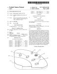
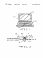
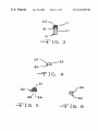
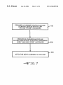
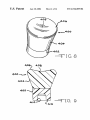
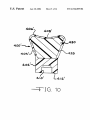
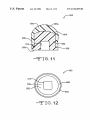
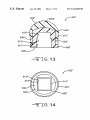
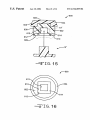
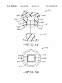
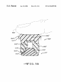
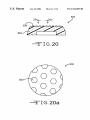
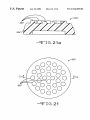
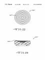
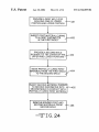
US006724369B2
(12) United States Patent
(10) Patent N0.:
US 6,724,369 B2
(45) Date of Patent:
*Apr. 20, 2004
Slotta
(54)
TEXTURED CUSHION FOR KEYBOARD
5,488,206 A
CURSOR CONTROL STICK
5,504,502 A
5,568,987 A
4/1996 Arita et al.
10/1996 FranZ
5,570,112 A
10/1996 Robinson
(75) Inventor: Mark R. Slotta, Highland, MI (US)
'
.
5,670,988 A
-
5,691,747 A
(73) Asslgnee' GIV’ LLC’ Hlghland’ MI (Us)
.
(ak)
.
Nome:
.
5,694,123 A
.
.
5,701,142 A
5,705,778 A *
5,708,562 A
U-S-C- 154(b) by 0 days~
5,712,660 A
12/1997
Brown et al.
1/1998 Matsuietal. ........... .. 200/11 R
1/1998 Agata et a1_
1/1998 Martin
5/1998
5,798,754 A
*
8/1998 Selker et al. ............. .. 345/161
Baba ........................ .. 345/157
(List continued on next page.)
OTHER PUBLICATIONS
Jul_ 12’ 2002
IBM ThinkPad 750 and 750C User’s Manual pp. 4—27
PriOI‘ PubliCatiOIl Data
through 4—29, dated prior to invention.
Santoprene Thermoplastic Rubber. Datasheet. [online].
US 2004 0056841 A1 M
/
at
Advanced Elastomer
Systems ’ L.P. [retrieved on Oct. 30 ’
.
. 25 2004
’
2000]. Retrieved from the Internet <URL:WWW.santo
Related US Application Data
(60)
Amano ..................... .. 345/167
12/1997 Selker et al.
*
(21) Appl.No.: 10/194,715
(65)
11/1997
5,754,166 A
Clalmer'
Filed:
1/1996 Wu .......................... .. 200/6 A
9/1997 Tickle
*
sublectto any dlsclalmeritheterm Ofthls
patent is extended or adJusted under 35
This patent is Subject to a terminal dis_
(22)
*
prene.com/aes/santoprene.html>.
L' t
Continuation-in-part of application No. 09/703,041, ?led on
Oct. 31, 2000, which is a continuation-in-part of application
No. 09/281,126, ?led on Mar. 29, 1999, now Pat. No.
6,140,998, which is a division of application No. 08/717,
220, ?led On Sep. 26, 1996, now Pat. NO. 5,889,508.
7
t'
d
t
.
( 15 Con lnue on neX page)
Primary Examiner_Regina Liang
-
~
_
-
Assistant Examiner Jenmfe? T' Nguyen,
_
(74) Attorney) Agent) or Flrm—MaCM111an> Sobanskl &
Todd, LLC
(51)
Int. Cl. ................................................ .. G09G 5/08
(52)
US. Cl. ..................... .. 345/161; 345/157; 345/158;
(57)
_
345/156; 345/160; 345/163
Fleld Of Search ............................... ..
A gel cushion that can be attached to an existing cursor
pointing device (Control Stick) on a Computer or keyboard,
345/156’ 160’ 161’ 163
,
References Clted
US PATENT DOCUMENTS
or be integrally formed With the cap during manufacture.
The gel cushion is ?exible enough to prevent tissue damage
to the user’s ?ngers due to repetitive motions over an
extended period of use, yet ?rm enough to transmit the
desired pressure to the control stick. The gel cushion
(56)
3’292’397 A
8/1975 Eff/Ore et a1‘
designed to be used on an existing control stick can be
1836382 2 *
H515; """""""""""" "
5’087’904 A
2/1992 D evolp'i' """"""""""" "
51347008 A
7/1992 Alm
5,290,115 A
5,407,285 A
*
3/1994
Little
ABSTRACT
applied With an adhesive to a cap, or With a frictional ?t
directly to the control stick. The gel cushion is designed to
be easily installed and replaced When Worn.
....................... .. 400/491
4/1995 Franz
103 Claims, 14 Drawing Sheets
l2.
'7
\NS\DE OF COVER m .
\5 WHEN CLO$ED
US 6,724,369 B2
Page 2
U.S. PATENT DOCUMENTS
5,870,082
5,889,507
5,889,508
6,019,534
6,040,758
6,057,540
6,135,476
6,140,998
6,239,786
6,271,834
6,353,431
6,390,423
6,400,354
2/ 1999
3/ 1999
3/ 1999
2/2000
3/2000
Selker et a1.
Engle et a1.
Slotta
Heins
Sedor et 81.
5/2000 Gordon et a1.
10/2000 Dickie et a1.
* 10/ 2000
5/2001
8/2001
3/2002
5/2002
OTHER PUBLICATIONS
TPE Applications for Broad Industry Needs. Information
sheet [online]. Advanced Elastorner Systems, L.P. [retrieved
on Oct. 30, 2000]. Retrieved from the Internet <URL:
WWW.sant0prene.corn/aes/applications.htrn1>.
IBM ThinkPad R40. CNET Reviews, 2003 [retrieved May
Slotta ....................... .. 345/161
28, 2003]Retrieved from Internet: <http://c0rnputers.cnet.
c0rn/hardWare/0—1027—405—20833353—1.htrn1>.
Burry et al.
May et a1.
IBM ThinkPad R40. PC Watch Japan, Jan. 29, 2003; [re
trieved 2003—05—28] Retrieved from Internet: <http://pc.
Poole et a1.
Watch.irnpress.c0.jp/d0cs/2003/0129/ibrn.htrn>.
DanZyger et a1.
6/2002 Pin-Chien
* cited by examiner
U.S. Patent
Apr. 20, 2004
Sheet 1 0f 14
US 6,724,369 B2
I:
U
D
m
J!
"716. l
F
\ICRw
ms mwEH om. co.W0E5
4
_T
Ill]
U.S. Patent
Apr. 20, 2004
2O
Sheet 2 0f 14
US 6,724,369 B2
22.
24
".r" I6. 4
32
30
as
54
IG. 5
%34
3O
:‘I6. 6
U.S. Patent
Apr. 20, 2004
Sheet 3 0f 14
US 6,724,369 B2
PROVIDE A CURSOR POINTING DEVICE
(CONTROL STICK) WITH A CAP
HAVING A FIRST HARDNESS
100
/
PROVIDE A CUSHION HAVING AN
OUTER SURFACE OF A SECOND HARDNESS
LESS THAN SAID FIRST HARDNESS
-—20O
/ 300
AFFIX THE SOFT CUSHION TO THE CAP
U.S. Patent
Apr. 20, 2004
Sheet 4 0f 14
US 6,724,369 B2
U.S. Patent
Apr. 20, 2004
Sheet 5 0f 14
US 6,724,369 B2
U.S. Patent
Apr. 20, 2004
Sheet 6 6f 14
US 6,724,369 B2
f‘ 500
16.11
f
500
510
508
504
16.12
U.S. Patent
Apr. 20, 2004
Sheet 7 0f 14
US 6,724,369 B2
f- 500'
f 500'
513'
510’
514’
509,
504
502'
508'
-—'::_'IG. 14
U.S. Patent
Apr. 20, 2004
Sheet 10 0f 14
US 6,724,369 B2
U.S. Patent
Apr. 20, 2004
Sheet 11 0f 14
US 6,724,369 B2
800
20a_i__ _t20a
830
804
/
-—::'IG. 20
830
-—_-'FIG. 20a
/
U.S. Patent
Apr. 20, 2004
Sheet 12 0f 14
87
804
__:_'IG.21
US 6,724,369 B2
U.S. Patent
Apr. 20, 2004
Sheet 13 0f 14
US 6,724,369 B2
r800"
830"
:_'IG.22
U.S. Patent
Apr. 20, 2004
Sheet 14 0f 14
US 6,724,369 B2
PROVIDE A FIRST MOLD FOR
MOLDING ONE OF LOWER
/\451
PORTION AND UPPER PORTION
V
INSERT FIRST MATERIAL CURING
TO A FIRST DUROMETER
_,/“452
IN THE FIRST MOLD
V
PROVIDE A SECOND MOLD
IN SHAPE OF THE OTHER OF THE /-453
UPPER AND LOWER PORTIONS T
V
MOvE PARTIALLY CURED FIRST
MATERIAL FROM THE FIRST MOLD
TO THE SECOND MOLD
454
~/
V
INJECT SECOND MATERIAL CURING
TO SECOND DUROMETER INTO /’\455
SECOND MOLD IN CONTACT WITH
PARTIALLY CURED FIRST MATERIAL
V
REMOvE BONDED FIRST AND
SECOND MATERIALS FROM
SECOND MOLD
,-\ 456
US 6,724,369 B2
1
2
TEXTURED CUSHION FOR KEYBOARD
CURSOR CONTROL STICK
control stick during a representative task, such as Word
processing, Will typically be at least every ten minutes, on
average, and may be much more frequently, depending on
the particular task and the particular user.
CROSS REFERENCE TO RELATED
APPLICATIONS
This application is a Continuation-In-Part of US. patent
application Ser. No. 09/703,041, ?led on Oct. 31, 2000,
Which Was a Continuation-In-Part of US. patent application
Ser. No. 09/281,126, ?led on Mar. 29, 1999, now US. Pat.
No. 6,140,998, Which Was a Divisional of Application Ser.
No. 08/717,220 ?led Sep. 26, 1996, now US. Pat. No.
Another type of a cap for a control stick has a hard
textured outer surface. For example, one knoWn control stick
is equipped With a cap Which is stippled With bumps Which
are about the same siZe and spacing as the abrasive on 150
grit sandpaper. While this approach may help prevent the
10
slipping common With the earliest model cap, the textured
cap is still irritating to the ?nger of a user When used
extensively, even With the lighter touch alloWed by the
5,889,508.
textured surface. The uneven and relatively hard surface of
such caps still can cause in?amed tissue, bruising, soreness
BACKGROUND OF THE INVENTION
15
This invention relates in general to a computer-input
device and in particular to a cursor-pointing device (cursor
control stick), of a notebook-type portable computer or
similar device.
A ?nger mouse or cursor control stick, as used in this
application, is a man-machine interface device, Which con
trols the motion of a computer display cursor. In particular,
a control stick is a type of miniature joystick, Which is
intended to be operated by the tip of one ?nger of the user.
Typically, a control stick is mounted in a central location
on a computer keyboard, such as betWeen the “G”, “H” and
“B” keys on a standard “QWERTY”-type keyboard. The
and ?nger fatigue in users Which limits their ability to
comfortably use such a control stick for periods of extended
use.
The present invention provides a “cushioned” cap for a
control stick, Which cap may suitably be formed from tWo
20
materials having different durometers (measures of
hardness), With a ?nger contact surface Which provides the
needed ?nger-to-cap friction to easily use the control stick to
move the cursor With a light touch, and Which is formed of
a relatively soft material, so that the cap does not irritate the
25 body tissues of the user or result in ?nger fatigue, even after
periods of extended use. Asoft texturing may be added to the
?nger contact surface.
control stick has a position sensing mechanism, Which
Various objects and advantages of this invention Will
detects horiZontal pressure in any horiZontal direction. The
cursor moves in a direction that corresponds to the direction
of pressure exerted on the control stick and, in some
embodiments, at a speed that corresponds to the amount of
pressure exerted on the control stick. The control stick
includes an elongated shaft. The shaft of the control stick has
a small diameter, thus alloWing the control stick to be
30
Heins, US. Pat. No. 6,019,534, discloses a gripping
device for a Writing instrument With a plurality of annular
ribs formed of soft rubber With an internal gel ?lled cham
ing detailed description of the preferred embodiment, When
read in light of the accompanying draWings.
BRIEF DESCRIPTION OF THE DRAWINGS
35
mounted betWeen the keys of the computer keyboard With
out causing the placement of the keys to vary greatly from
that expected by an experienced user. A cap is typically
removably mounted on the upper end of the control stick
shaft, in order to provide an enlarged contact surface for a
user to press against on the small diameter shaft of the
control stick.
become apparent to those skilled in the art from the folloW
40
FIG. 1 is a perspective vieW of a typical portable com
puter employing a control stick having a cushioned cap in
accordance With this invention.
FIG. 2 is a side vieW, partly in section, of the control stick
illustrated in FIG. 1.
FIG. 3 is an enlarged sectional side vieW of the cap and
the control stick illustrated in FIGS. 1 and 2.
FIG. 4 is a side vieW of the cushioned cap illustrated in
FIGS. 1 through 3.
45
ber. It is knoWn to use a gel material con?ned in a chamber
as is shoWn in Heins.
SUMMARY OF THE INVENTION
FIG. 5 is a sectional side vieW of a second embodiment of
a cushioned cap in accordance With this disclosure.
FIG. 6 is a bottom plan vieW of the cap illustrated in FIG.
5.
FIG. 7 is a ?oWchart illustrating a method of manufac
turing a control stick in accordance With this disclosure.
50
Some models of control sticks have a cap With a hard
smooth surface, Which became slippery during use from
FIG. 9 is a side sectional vieW of the gel cushion of FIG.
perspiration or a build-up of natural body oils. Thus a user
8.
has to press their ?nger With relatively great force against the
cap to prevent their ?nger from slipping on the surface of the
FIG. 8 is perspective vieW of a gel cushion for a keyboard
cursor control stick.
55
FIG. 10 is a vieW similar to FIG. 9, except shoWing an
cap. The need to press hard on the cap makes control
dif?cult, since the user cannot use the ?nesse and delicate
alternate embodiment of the gel cushion.
movements typically needed for rapid, accurate cursor
movement. Also, pressing hard on the control stick is
alternate embodiment of the gel cushion.
FIG. 12 is a bottom plan vieW of the gel cushion illus
physically tiring to the ?nger, hand and forearm muscles of
trated in FIG. 11.
FIG. 13 is a vieW similar to FIG. 11, except shoWing an
FIG. 11 is a vieW similar to FIG. 9, except shoWing an
a user, and causes irritation, in?ammation, and bruising of
the ?nger tissue after a period of extended use.
A period of extended use, as used in this application,
alternate embodiment of the gel cushion.
FIG. 14 is a bottom plan vieW of the gel cushion illus
means a period of use of more than about one hour, and
generally more than four hours and less than tWelve hours.
During such period of use, the user frequently manipulates
the control stick. The frequency of manipulation of the
65
trated in FIG. 13.
FIG. 15 is a vieW similar to FIG. 11, except shoWing an
alternate embodiment of the gel cushion and With stick
guide.
US 6,724,369 B2
3
4
FIG. 16 is a bottom plan vieW of the gel cushion illus
trated in FIG. 15.
FIG. 17 is a vieW similar to FIG. 13, except showing an
alternate embodiment of the gel cushion and With stick
prior art cap, such as a cap supplied With the TrackPoint II
control stick, is made of a relatively hard elastomeric
material. During testing, a probe having a contact surface of
approximately 1 square millimeter Was pressed against such
guide.
a cap to cause the probe to de?ect the surface of the cap
FIG. 18 is a bottom plan vieW of the gel cushion illus
trated in FIG. 17.
FIG. 19 is a vieW similar to FIG. 16, With the gel cushion
deformed under the pressure of a user’s ?nger.
grams Was required to compress the surface of the cap
inWardly this small amount. In contrast, one embodiment of
the cushion 20 of the present invention required a force of
approximately 0.25 millimeters. Aforce of approximately 15
1O
FIG. 20 is a cross sectional vieW of the cushioned cap
illustrated in FIG. 18.
FIG. 20a is an enlarged top vieW of a third embodiment
of the cushioned cap With textured surface illustrated in FIG.
20, taken along the line 20a—20a.
ness (or “durometer”) Which Would permit a probe having a
15
FIG. 21 is a cross sectional vieW of the cushioned cap
invention has a hardness such that only 5 grams of force is
required to cause a probe having a contact surface of 1
square millimeter to de?ect the surface of the cushion 20 by
at least 0.25 millimeters.
21, taken along the line 21a—21a.
FIG. 22 is similar to FIG. 18, except shoWing an alternate
embodiment of the textured surface.
FIG. 23 is a cross sectional vieW of the cushioned cap
25
Referring noW to the draWings, FIGS. 1 through 6 illus
phantom line 19, but Will resiliently return to the position
indicated by the solid outline of the cushion 20. The resil
trate a ?rst embodiment of a control stick, indicated gener
ally at 10, according to this invention. The illustrated control
35
computers sold by the International Business Machines
Corporation. HoWever, it Will be appreciated, in light of the
folloWing disclosure, that the invention may be practiced on
control devices other than such miniature joysticks. The
various devices such as computers, cellular phones, MP3
Referring to FIGS. 3 and 4, the cushion 20 is, preferably,
players, and personal digital assistants.
a disk of material having a generally semi-circular cross
The control stick 10 is mounted in a keyboard 12 of a
mounted display screen 15. The control stick 10 is mounted
iency of the cushion 20 alloWs the cap 18 to have an enlarged
contact surface area and greater height above the keyboard
12 for increased comfort of the user, Without having to
increase the spacing betWeen the display screen 15 and the
keyboard 12. It Will be appreciated by those skilled in the art
that the cushion 20 Will preferably not be made from a
material Which Would damage or stick to the display screen
15 if the display screen 15 contacts the cushion 20.
cursor control stick of the present invention can be used in
typical notebook-style microcomputer 14 having a pivotally
Preferably, the cushion 20 also provides a high coef?cient
of friction With the user’s ?nger to permit easy positioning
of the control stick 10. The polyurethane foam of the cushion
20 is yielding to a degree dependent upon the thickness of
the cushion 20. The thickness of the cushion 20 can easily
be modi?ed during manufacture to any desired thickness.
Referring to FIG. 2, When the display screen 15 is folded
doWn over the keyboard 12 for storage, as is typical for most
notebook computers, the display screen 15 may contact the
cushion 20. The cushion 20 is ?attened as indicated by the
DETAILED DESCRIPTION OF THE
PREFERRED EMBODIMENT
stick 10 is a miniature joy stick, such as the Trackpoint,
Trackpoint II, or Trackpoint III control sticks on notebook
contact surface of approximately 1 square millimeter to
de?ect the surface of the cushion 20 by at least 0.25
millimeters When urged by a force of 10 grams, Would
generally be acceptable. The preferred embodiment of the
illustrated in FIG. 18.
FIG. 21a is an enlarged top vieW of a fourth embodiment
of the cushioned cap With textured surface illustrated in FIG.
illustrated in FIG. 22.
FIG. 24 is a ?oWchart illustrating a method of manufac
turing a gel cushion in accordance With this disclosure.
only 5 grams to be exerted by the probe to compress the
surface of the cushion 20 the same distance. According to
the invention, a cushion 20 having a measurement of hard
section. HoWever, the cushion 20 may have any suitable
45
at a ?rst end (not shoWn) to the microcomputer 14, betWeen
the keys of the keyboard 12. Acap 18 is removably mounted
shape, such as that of a ?at-ended or holloW-ended cylinder.
In the illustrated embodiment, the cushion 20 has a convex
end 22, and a second end 24. The convex end 22 is the
contact surface of the cushion 20, that is, the surface that the
on the other end 21 of the control stick 10. The control stick
user of the control stick 10 Will contact to move the control
10 is usually made of a plastic material, and translates the
stick 10. The convex end 22 Will generally be a surface
pressure on the cap 18 into a command to move a cursor on
providing a good frictional interface. In the preferred
embodiment, the convex end 22 is a sealed, smooth, easily
a video display of the computer 14.
The cap 18 of the control stick 10 is made of a relatively
hard elastomeric material. At least a central portion of the
outer surface 17 of the cap 18 is provided With an attached
cleaned surface, such as a closed cell skin formed on
polyurethane foam. The resiliency of the cushion 20 permits
55
cushion 20. The cushion 20 can be made of any resilient
material that can be attached to the outer surface 19 of the
cap 18. Examples, Which may be suitable materials, include
the cushion 20 to be deformed and still provide excellent
friction, even When the surface thereof is smooth. HoWever,
if desired, the surface of the convex end 22 may be textured
or knurled. The second end 24 of the cushion 20 Will be
soft rubber, soft foam, and polyurethane foam. The preferred
attached to the outer surface 19 of the cap 18 on the control
material for the cushion 20 is polyurethane foam such as the
stick 10. In the preferred embodiment, a suitable adhesive is
type used in expandable earplugs. This type of foam product
used to attach the cushion 20 to the outer surface 19 of the
cap 18.
FIG. 5 is a sectional vieW of a second embodiment of the
provides a ?nger contact surface that is relatively soft so as
not to damage the tissues in the ?nger of a user during
periods of extended use.
Hardness can be characteriZed by measuring the force
applied to a given area Which is required to compress or
de?ect a material a given distance. For example, a typical
cushion of this invention, indicated generally at 30. The
65
cushion 30 is generally cylindrical and includes a convex
end 32, and a relatively ?at end 33 opposite the end 32.
Although in the illustrated embodiment the end 32 is
US 6,724,369 B2
5
6
convex, the end 32 may be formed to any suitable shape,
cavity. Such a ?ange of material Would restrict the siZe of the
opening into the cavity to a diameter Which is less than the
diameter of the cap 18, and thus retain the cushion on the cap
such as a ?at or a concave surface, as may the end 22 of the
cushion 20.
A recess 34 is de?ned in the cushion 30, Which generally
conforms to the outer surface of the end 21 of the control
stick 10. For example, as shoWn in FIG. 6, the recess 34 may
have a square perimeter, if the end 21 of the control stick 10
is square in cross-section. The control stick 10 extends into
the recess 34. Preferably, to install the cushion 30 onto the
control stick 10, a suitable adhesive is applied to the upper
end 21 of the control stick, to the interior surface of the
recess 34 in the cushion 30, or to both the upper end 21 of
the control stick and to the interior surface of the recess 34
in the cushion 30. The cushion 30 is placed on the end 21 of
the control stick 10 so that the cushion 30 adheres to the end
21 of the control stick 10. Of course, the cushion 30 could
also be af?xed to the control stick 10 by a resilient ?t
betWeen the recess 34 of the cushion 30 and the end 21 of
the control stick 10. The cushion 30 is comprised of a soft
material to permit use for an extended period of time Without
18, either alone or in combination With a suitable adhesive.
The opening into such a cushion could be resiliently
expanded to slip the cushion onto the cap 18 during
assembly, or When the cushion is replaced.
Although the preferred embodiment of the cushion 20 or
10
15
30 is for use on a portable notebook computer 14, it is
envisioned that the cushion 20 or 30 could be used on any
keyboard or in any convenient location on any instrument
requiring a control stick-like movement.
It is contemplated that the cushions 20 or 30 of the present
invention can be sold separately from a notebook-type
portable computer as replacements or substitutes to the
original control stick and cap con?guration. The cushions 20
or 30 can be sold in a kit form, Which preferably includes the
necessary materials to af?x the cushions 20 or 30 to a control
stick of a computer. The kit may include a plurality of
cushions 20 or 30 and a suitable adhesive material, such as
causing irritation to the ?nger tissue.
a container of contact cement or a pressure sensitive self
adhesive strip Which is pre-applied to the cushions 20 or 30.
For example, if contact cement is supplied With the kit, the
It may be desirable to manufacture the cushion 30 With
portions having different levels of hardness. For example,
the convex end 32 could be softer than the area of the
user simply applies a coating of contact cement to either the
cushion 30 surrounding the recess 34. The harder area 25 originally supplied cap 18 or the end 21 of the control stick
surrounding the recess 34 Would assist in retaining the
cushion 30 on the control stick 10 by maintaining its form,
While the convex end 32 of the cushion could be relatively
soft.
One method of manufacturing the cushion 30 With por
tions having different levels of hardness Would involve
10, depending on the type of cushion 20 or 30 used. A
coating of contact cement is also applied to the cushion 20
or 30. The coatings of contact cement are then alloWed to
dry. The cushion 20 or 30 is then pressed against the coated
portion of the original cap 18 or control stick 10, thereby
Which is harder than the ?rst material Would be injected in
af?xing the cushion 20 or 30 to the control stick 10.
FIG. 7 is a How diagram of a method of forming a
cushioned control stick according to the invention. The
method of forming a cushioned control stick may be sum
mariZed as folloWs: In a ?rst step 100, a cursor pointing
device (control stick) With a cap having a ?rst hardness is
provided. In a second step 200, a soft cushion is provided
the mold at the area Where the recess 34 is formed. Accel
Which has an outer surface of a second hardness Which is
erating agents, compatabiliZing agents, ?llers, mold release
less than the ?rst hardness of the cap (i.e., the cushion is
softer than the cap). In a third step 300, the soft cushion is
af?xed to the relatively harder cap.
It Will be appreciated that the soft cushions described
above may be formed in a variety of Ways, of a variety of
materials. For instance, in an embodiment shoWn in FIG. 8,
a cushion, indicated generally at 400, is formed of a gel
material. As used herein, the term gel means a semi-rigid
solid, and includes a colloidal suspension of a solid dis
persed in a liquid, and materials With similar characteristics
simultaneously injecting tWo separate types of material
simultaneously into a cavity of single mold to form the
cushion 30. For example, a ?rst material having relatively
soft properties Would be injected in the mold at the area
35
Where the convex end 32 is formed, and a second material
agents, and coloring agents can be introduced as Well, as Will
be appreciated by those skilled in the art. SomeWhere
betWeen the tWo ends 32 and 33, the ?rst and second
materials come into contact and become af?xed to one
another. The cushion 30 Would, therefore, be a single
structure formed from tWo different materials, having dif
45
ferent hardness characteristics When set or cured. For the
purposes of the present invention, curing can be accom
plished by using any suitable methods of solidifying or
hardening a material, such as for example, by adding or
removing heat, inducing a catalytic reaction, or containment
as load bearing surfaces (e.g., stiffness, hardness,
malleability, etc.).
for a period of time to alloW hardening to occur.
The cushion 400 preferably has a generally cylindrical
loWer portion 402, and a generally conic upper portion 404,
Another method of manufacturing the cushion 30 having
multiple areas With different levels of hardness Would be to
form the cushion 30 from a single material, but altering the
Which increases in diameter toWard an upper surface 406 of
have different hardness characteristics. This alteration of the
the cushion 400. Thus, at least a portion of the upper portion
404 is generally frustoconical. The upper surface 406 is
preferably formed With a depression 408 therein that is
formation process can be accomplished by varying the
suitable to receive a ?ngertip of a user.
55
setting or formation of the material so that the different areas
temperature gradient surrounding the mold, creating minia
Like the cushions described in the other embodiments
ture air pockets Within selected portions of the material, or
above, the cushion 400 Will deform if pressed against the
computer display screen. It is contemplated that the cushion
by any other suitable manufacturing process.
As an alternate embodiment, it is contemplated that a
cushion of the invention could be formed to completely
encompass the cap 18 shoWn in FIGS. 2 and 3, except Where
the shaft of the control stick 10 extends outWardly there
from. Such a cushion Would have a cavity therein, Which
includes a ?ange of material about an opening into the
400 may be manufactured to have a suitable relatively rigid
pocket (seen in FIGS. 9 and 10) to accept the upper end of
a control stick of a computer, such as the control stick 10. It
65
is also contemplated that the cushion 400 could otherWise be
?xed to a control stick cap like the cap 18 in FIG. 2, such as
by adhesively ?xing the cushion 400 to the cap. It is also
US 6,724,369 B2
7
8
contemplated that the cushion 400 may be manufactured to
form an integral part of a removable control stick or portion
In the preferred embodiment, the ?rst material is removed
from the ?rst mold as soon as suf?ciently cured to be parted
from the ?rst mold.
In a ?fth step 455, a second material curing to a second
of a control stick (not shoWn).
FIG. 9 is a cross sectional vieW of the cushion 400. The
durometer, different from the ?rst durometer, is injected into
upper portion 404 of the cushion 400 is made from a
different material than the loWer portion 402. The upper
portion 404 may be made from any suitable material. It is
believed that thermoplastic elastomeric compounds such as
the second mold in contact With the partially cured ?rst
material so that the second material bonds to portions of the
partially cured ?rst material With Which the second material
comes into contact. In the preferred embodiment in Which
KRATON® thermoplastic elastomers (available from the
the ?rst mold provided in step 451 is the loWer portion 402,
Royal Dutch/Shell Group) or thermoplastic rubber com
pounds such as SAN TOPRENE® (available from Advanced
Elastomer Systems, L.P., 388 South Main Street, Akron,
Ohio, USA. 44311) may be particularly suitable for this
application. The material from Which the upper portion 404
the second material is a thermoplastic rubber material that
Will have a Shore A durometer of about 3 to about 10 When
is formed is selected to have a relatively loW hardness, so
that the upper portion 404 is relatively soft and compliant.
The upper portion 404, in a preferred embodiment, is cured
15
fully cured and Will form the upper portion 404. The upper
portion 404 is thus overmolded onto the partially cured
loWer portion 402, With the material of the upper portion 404
chemically bonding With the material of the loWer portion
402.
In a sixth step 456, both the ?rst and second materials are
removed from the second mold. One or both of the ?rst and
to a Shore A durometer of about 3 to about 10, though of
course some variance from this softness may be desirable in
second materials may be fully cured before the bonded ?rst
certain applications, particularly if other features, such as air
pockets in the material of the cushion 400, are provided that
affect the overall feel of the cushion 400. The material of the
and second materials are removed from second mold.
Similarly, one or both of the ?rst and second materials may
only be partially cured before the bonded ?rst and second
upper portion 404 may be a gel or a gel contained in a
materials are removed from second mold.
non-gel pocket. The loWer portion 402 de?nes a pocket 410
in a loWer surface 412 thereof. The pocket 410 is adapted to
In a preferred embodiment, the mold for the upper portion
cursor control stick 10. The loWer portion 402 is preferably
406 of the upper portion 404 is textured corresponding to the
abraded surface of the mold. The inner surface of the mold
receive the upper end of a cursor control stick, such as the 25 404 has an abraded inner surface such that the upper surface
formed of a material With a higher durometer than the upper
may be abraded in any conventional manner, such as by sand
portion 404. The loWer portion 402 may, nevertheless, be
blasting or by electrical discharge machine. In a preferred
embodiment, the mold for the upper portion 404 has an inner
formed of any suitable material. It is believed that thermo
plastic rubber compounds may be particularly suitable for
this application. The loWer portion 402 is preferably cured to
surface With a textured pattern such that the upper surface
406 of the upper portion 404 is textured corresponding to the
textured surface of the mold.
An alternate embodiment of the cushion 400 is illustrated
by the cross sectional vieW of FIG. 10. A cushion 400‘ is
similar in outer shape to the cushion 400 illustrated in FIG.
be relatively harder than the upper portion 404, such as to a
Shore A durometer of about 55 to about 65.
These thermoplastic elastomeric and rubber materials are
believed to be particularly suitable because of the tack their
surfaces have, Which gives the cushion 400 a smooth,
8, and has similar qualities of deformation for comfort and
protection of computer display screens, and smoothness and
non-irritating, yet non-slip surface for improved perfor
mance.
tack for ergonomic reasons. HoWever the cushion 400‘ is
constructed someWhat differently, as Will be described.
Like the cushion 400, the cushion 400‘ preferably has a
The cushion 400 may be formed With any suitable
machinery of any suitable material by any suitable process.
Thermoplastic rubber compounds, for example, can be
generally cylindrical loWer portion 402‘, and a generally
injection molded, extruded, bloW molded and thermoformed
conic upper portion 404‘, Which increases in diameter
With the ef?ciency and economy associated With thermo
plastic materials. As a further example, the cushion 400 may
be formed of thermoplastic rubber compounds using a
toWard an upper surface 406‘ of the cushion 400‘. The upper
45
surface 406‘ is preferably formed With a depression 408‘
therein that is suitable to receive a ?ngertip of a user.
tWo-step injection process on standard thermoplastic injec
tion molding equipment. In a preferred process, illustrated in
The loWer portion 402‘ of the cushion 400‘ is formed of
any suitable material, and, like the cushion 400, is preferably
FIG. 23, the cushion 400 is formed in a tWo step injection
formed of a thermoplastic rubber compound such as SAN -
molding process.
TOPRENE® thermoplastic rubber. The loWer portion 402
In a ?rst step 451, a ?rst mold is provided, shaped to form
one of the loWer portion 402 and the upper portion 404. In
one preferred embodiment, the ?rst mold is shaped to form
pocket 410‘, like the pocket 410 in the cushion 400, is
the loWer portion 402.
such as the cursor control stick 10.
de?nes a pocket 410‘ in a loWer surface 412‘ thereof. The
adapted to receive the upper end of a cursor control stick,
In a second step 452, a ?rst material curing to a ?rst 55
The upper portion 404‘ of the cushion 400‘ is of someWhat
durometer is injected into the ?rst mold. In the preferred
embodiment in Which the ?rst mold is the loWer portion 402,
different structure that the cushion 400. The outer surface of
the ?rst material is a thermoplastic rubber material that Will
have a Shore Adurometer of about 55 to about 65 When fully
cured.
In a third step 453, a second mold is provided, shaped to
moplastic rubber compound such as SANTOPRENE® ther
moplastic rubber Would be suitable in this application, and
form the other of the loWer portion 402 and the upper portion
404. In the preferred embodiment in Which the ?rst mold is
the loWer portion 402, the second mold is shaped to form the
upper portion 404.
In a fourth step 454, the molded ?rst material is removed
While only partially cured, and placed into the second mold.
the upper portion 404‘ is an envelope 428, Which may be
formed of any suitable material. It is believed that a ther
the envelope 428 is preferably formed integrally With the
loWer portion 402‘. The envelope 428 is ?lled With a suitable
material 430. The material 430 may be any suitable gel, such
65
as a silicone gel, or a thermoplastic elastomeric compound
such as KRATON® thermoplastic elastomer formulated to
form a loW durometer (hardness) (i.e., to form a very soft)
material.

![[quote(var.text)]}](http://vs1.manualzilla.com/store/data/005937533_1-4dd3fe8a9b5a28fbfb6fbb268c8e3b66-150x150.png)