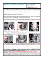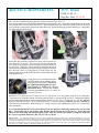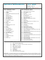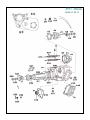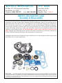
1
ADVANCE ADAPTERS INC.
P/N: Orion
P.O. Box 247, 4320 Aerotech Center Way
Paso Robles, CA 93447
Telephone: (800) 350-2223
Fax: (805) 238-4201
New Item: (06/04)
PAGE 1 OF 15
Page Rev. Date: 12-02-15
ORION TRANSFER CASE
Assembly & Disassembly
The Orion was created to replace stock transfer cases built between the years of 1963 and July of 1980. This case
replacement is the same external width, eliminating driveline modifications; however, the drain plug may be
approximately .500" lower than a stock case. The supplied 4:1 gear set replaces the existing gear set except for the
P.T.O. gear or P.T.O. spacer sleeve. It is required that you reuse your stock fasteners, front and rear housings,
retainers, shafts, clutch sleeves, and cover plates from your original transfer case. You are supplied a full rebuild kit
to replace all bearings, bearing cups, O-rings, seals, and gaskets. Shims for the rear output shaft retainer are also
supplied to set the bearing pre-load. Do not discard shims, washers, sleeves, and spacers from yokes and
shafts. Throughout the disassembly section, reference will be made to items that may be discarded. Attached you
will find 3 different illustrations referring to each component by our common terms.
Although this instruction sheet will initiate the steps to install the Orion, it is advised that you obtain a shop or repair
manual that covers your specific application.
SPECIAL NOTE:
The components packaged in this kit have been assembled and machined for specific type of conversions. Modifications to any of the components
will void any possible warranty or return privileges. If you do not fully understand modifications or changes that will be required to complete your conversion, we strongly
recommend that you contact our sales department for more information. This instruction sheet is only to be used for the assembly of Advance Adapter components. We
recommend that a service manual pertaining to your vehicle be obtained for specific torque values, wiring diagrams and other related equipment. These manuals are normally
available at automotive dealerships and parts stores.
ADVANCE ADAPTERS INC.
P/N: Orion
P.O. Box 247, 4320 Aerotech Center Way
Paso Robles, CA 93447
Telephone: (800) 350-2223
Fax: (805) 238-4201
New Item: (06/04)
PAGE 2 OF 15
Page Rev. Date: 12-02-15
ORION TRANSFER CASE POINTS OF CONCERN (PLEASE READ)
The success of an Orion Transfer case installation is dependant on the condition of the necessary components that are to be reused
from your stock case. Some of the most critical components that require your attention to detail are as follows: Note: We stock both
the output shafts and Hi/Low clutch sleeve, these parts are new not used.
G26- HI/LOW CLUTCH SLEEVE - Inspect for excessive or worn splines. The splines should not be tapered throughout the sleeve
width. You will notice the “V” looking tapers or “boat tails” only at the last .070” to the contact sides of the sleeve towards
each gear.
S5 & S6- SHIFT FORK LOCK BALL AND COMPRESSION SPRING - We have provided a new ball, spring, and brass set screw to
be used for your installation. The ball provided measures 10mm and will tighten up the tolerance in the shift fork bore. We have
also provided a new spring which has a greater holding capacity than an older worn out spring. The new brass set screw will take
the guess work out of setting the tension on the spring and ball inside the new shift fork. The brass set screw should be installed
with a bit of Loctite to retain it, and the hex should be seated completely to the shift fork. Note: the new shift rail is retained by a
cone point set screw.
G22 & G29- THRUST WASHERS - The thrust washers are an important and critical area when installing the Orion gears on your
Toyota shaft. The first step is to inspect the transfer case output shaft for excessive wear and to make sure the gears fits the shaft.
If your shaft is worn excessively, the gear will be a loose fit or will be able to wobble. If this is the case with your shaft, replace it.
We do offer replacement shafts.
If the shaft is in good shape, then proceed. The end play of the gear on the shaft must be set. The
new Orion gears are the same width as a stock gear set. On the early Orions the stock thrust washers
were retained and the end play on the gears is what the stock unit had. Unfortunately, in some
applications the end play ended up to be close to .030". The factory could have been off or if at
some time the output shaft was changed, it could have had different than stock measurements.
The shaft and gears should be set at .008"-.012" of end play. We now include two new thrust
washers to help set up the transfer case with the correct end play. These thrust washer are stepped.
One side has a recess of .015" - .017" and the other side of the washer has a .008" - .010" recess.
Note 1: Occasionally, machining of output shaft shoulder
may be necessary to achieve the required gear clearance.
Note 2: Test the gear clearance with the output
outside of the case on the bench. By using this
method you can eliminate having to remove the
assembly from the case to make adjustments.
Make sure to press on the bearings fully, install
the spacer, speedo gear and park brake drum.
Tighten the rear nut to verify that the bearing is
fully seated.
If you should have any further questions
please call us @ 1-800-350-2223.
SPECIAL NOTE:
The components packaged in this kit have been assembled and machined for specific type of conversions. Modifications to any of the
components will void any possible warranty or return privileges. If you do not fully understand modifications or changes that will be required to complete your conversion,
we strongly recommend that you contact our sales department for more information. This instruction sheet is only to be used for the assembly of Advance Adapter
components. We recommend that a service manual pertaining to your vehicle be obtained for specific torque values, wiring diagrams and other related equipment.
These manuals are normally available at automotive dealerships and parts stores.
ADVANCE ADAPTERS INC.
P/N: Orion
P.O. Box 247, 4320 Aerotech Center Way
Paso Robles, CA 93447
Telephone: (800) 350-2223
Fax: (805) 238-4201
New Item: (06/04)
PAGE 3 OF 15
Page Rev. Date: 04-18-05
ORION TRANSFER CASE
Assembly & Disassembly
Orion Instructions:
The following instructions cover the disassembly of your stock transfer case along with the assembly of the Orion
transfer case. Listed throughout these instructions, we refer to various item numbers. These item numbers represent
components on one of the three schematics shown at the end of these instructions. The item numbers listed represent
the following: "C" is the case schematic, "G" is the gear schematic, and "S" is the shifter schematic. These drawings
also have an index page that corresponds the common terminology of these components.
Drain gear lubricants from transmission and transfer case.
Remove the parking brake drum retaining nut.
On 1963 to 1973 10-spline T/C, or as we'll term 3 Speeds - Reference item #’s C9, C10, C11. Retain item C9
On 1974 to 1980 16-spline T/C, or as we'll term 4 Speeds - Reference item #’s C6, C7, C8. Retain items C6, C7
This should be done while still in the vehicle after
the front and rear drive shafts are removed. You
will be able to slide the brake drum off and then the
brake plate assembly. This will keep you from
having to remove the brake cable from the brake
plate. Once this is achieved, simply unscrew the
speedometer cable from the speedometer shaft
sleeve.
Stock Transmissions:
We strongly recommend that stock 3 and 4 speed transmission combinations be removed completely from the vehicle.
In order to remove the transfer case from your transmission, please refer to a manual that covers your application.
Advance Adapters (spud shaft style) transfer case adapter systems:
If you are removing a transfer case from a transmission that is using our conversion adapter, it is possible to only remove
the transfer case. It will be up to your own discretion to unbolt either the adapter housing from the transmission or the
transfer case from the adapter housing. In either instance, our conversion adapters require the transfer case to slide
rearwards only a few inches to disengage the transmission output shaft from our adapter spud shaft.
SPECIAL NOTE:
The components packaged in this kit have been assembled and machined for specific type of conversions. Modifications to any of the
components will void any possible warranty or return privileges. If you do not fully understand modifications or changes that will be required to complete your conversion,
we strongly recommend that you contact our sales department for more information. This instruction sheet is only to be used for the assembly of Advance Adapter
components. We recommend that a service manual pertaining to your vehicle be obtained for specific torque values, wiring diagrams and other related equipment.
These manuals are normally available at automotive dealerships and parts stores.
ADVANCE ADAPTERS INC.
P/N: Orion
PAGE 4 OF 15
Page Rev. Date: 04-18-05
Disassembly of Transfer Case:
Remove and retain output shaft rear bearing retainer C4.
You do not have to remove the speedometer assembly.
Remove and retain the speedometer drive gear and
spacer from the output shaft, Item #’s G32 & G33.
Remove and retain the front transfer
yoke. A wood block during removal
may help keep the flange of the yoke
from spinning.
When removing the yoke on 3 speed cases, retain washer C25; and
on 4 speed cases, retain both washer and shim C21 and C22.
SPECIAL NOTE:
The components packaged in this kit have been assembled and machined for specific type of conversions. Modifications to any of the
components will void any possible warranty or return privileges. If you do not fully understand modifications or changes that will be required to complete your conversion,
we strongly recommend that you contact our sales department for more information. This instruction sheet is only to be used for the assembly of Advance Adapter
components. We recommend that a service manual pertaining to your vehicle be obtained for specific torque values, wiring diagrams and other related equipment.
These manuals are normally available at automotive dealerships and parts stores.
ADVANCE ADAPTERS INC.
P/N: Orion
PAGE 5 OF 15
Page Rev. Date: 04-18-05
Remove and retain the front driveshaft shift assembly from your transfer case:
VacuumDiaphragm cylinder and transfer front drive fork
MechanicalTransfer front drive shift shaft guide assembly (pictured)
Remove and retain the transfer extension housing with
its internal parts, Items C28, G16, G17, G18, G20.
With a dead blow hammer, drive out
the front output shaft G18.
Remove and retain snap ring G16
from extension housing C28. Press
out ball bearing G17 and discard.
SPECIAL NOTE:
The components packaged in this kit have been assembled and machined for specific type of conversions. Modifications to any of the
components will void any possible warranty or return privileges. If you do not fully understand modifications or changes that will be required to complete your conversion,
we strongly recommend that you contact our sales department for more information. This instruction sheet is only to be used for the assembly of Advance Adapter
components. We recommend that a service manual pertaining to your vehicle be obtained for specific torque values, wiring diagrams and other related equipment.
These manuals are normally available at automotive dealerships and parts stores.
ADVANCE ADAPTERS INC.
P/N: Orion
PAGE 6 OF 15
Page Rev. Date: 12-29-05
Remove and retain case cover C13.
Remove the cotter pin, screw plug, compression spring, and shift fork lock ball from the
HI and LOW shift fork, Items S5, S6, S7, S8. Invert the case, if need be, to have the spring
and ball fall out. These parts will not be reused since a new shift assembly has been
provided.
Remove and retain the HI and LOW shift fork shaft lock plate and bolt S2.
Using a drift punch, lightly drive out the HI and LOW shift fork shaft S1
towards the rear of the transfer case.
Remove and discard the HI and LOW shift fork S4 and shift rail S1.
SPECIAL NOTE:
The components packaged in this kit have been assembled and machined for specific type of conversions. Modifications to any of the
components will void any possible warranty or return privileges. If you do not fully understand modifications or changes that will be required to complete your conversion,
we strongly recommend that you contact our sales department for more information. This instruction sheet is only to be used for the assembly of Advance Adapter
components. We recommend that a service manual pertaining to your vehicle be obtained for specific torque values, wiring diagrams and other related equipment.
These manuals are normally available at automotive dealerships and parts stores.
ADVANCE ADAPTERS INC.
P/N: Orion
PAGE 7 OF 15
Page Rev. Date: 04-18-05
Remove and retain the transfer case output shaft G25. This may be
accomplished by wedging the low speed output gear, G28, with a suitable
tool against the case to keep it from moving forward. Using a dead blow
hammer, lightly tap the shaft from the rear to drive it forward. This shaft
will come out the front of the case with the tapered roller bearing G21,
thrust washer G22, high speed gear G24, and the HI and LOW clutch
sleeve G26. You must retain the HI and LOW clutch sleeve G26, and
thrust washer G22. The tapered roller bearing may be discarded.
Remaining in the case will be the low speed
output gear, G28, thrust washer G29, and
tapered roller bearing G30. You need only to
retain thrust washer G29. The low speed
gear and roller bearing may be discarded.
Remove and retain the transfer case idler gear shaft
lock plate and bolt G15 only. The idler gear shaft, idler
gear, and case may be discarded.
Remove remaining seals, bearings, roller bearing cups,
and gears from the original components to be assembled
onto Orion. Clean all components thoroughly.
SPECIAL NOTE:
The components packaged in this kit have been assembled and machined for specific type of conversions. Modifications to any of the
components will void any possible warranty or return privileges. If you do not fully understand modifications or changes that will be required to complete your conversion,
we strongly recommend that you contact our sales department for more information. This instruction sheet is only to be used for the assembly of Advance Adapter
components. We recommend that a service manual pertaining to your vehicle be obtained for specific torque values, wiring diagrams and other related equipment.
These manuals are normally available at automotive dealerships and parts stores.
ADVANCE ADAPTERS INC.
P/N: Orion
PAGE 8 OF 15
Page Rev. Date: 04-18-05
Assembly:
With the rebuild kit provided, install the new seals, bearings, and roller bearing cups.
Press seal C18 into the Orion. Press seal C5 into the output shaft rear bearing retainer C4. Press ball bearing G17
into extension housing C28 and retain it with the original snap ring G16. Press seal C26 into extension housing.
Press tapered roller bearing cups G21 and
G30 into the Orion case and extension
housing C28. Note: G21 and G30 may be
installed after the output shaft assembly, HI
and LOW clutch sleeve, and low speed gear
are installed into the case.
Install the bearing spacer G10 between
needle bearings G9 into the new idler
gear G11. Add assembly lube.
Now, place the idler gear in position
in the case.
Place idler gear thrust washers G8
into position. Be sure to align the
locating tabs on the thrust washers
to the channels located on the inner
walls of the case.
SPECIAL NOTE:
The components packaged in this kit have been assembled and machined for specific type of conversions. Modifications to any of the
components will void any possible warranty or return privileges. If you do not fully understand modifications or changes that will be required to complete your conversion,
we strongly recommend that you contact our sales department for more information. This instruction sheet is only to be used for the assembly of Advance Adapter
components. We recommend that a service manual pertaining to your vehicle be obtained for specific torque values, wiring diagrams and other related equipment.
These manuals are normally available at automotive dealerships and parts stores.
ADVANCE ADAPTERS INC.
P/N: Orion
PAGE 9 OF 15
Page Rev. Date: 12-29-05
With idler gear and thrust washers in position, apply assembly lube to idler gear shaft G13.
Locate the groove cut into the idler shaft for the lock plate. Lightly lubricate and install the O-ring on this end
only. Install the opposite end of the idler shaft , into the rear side of the transfer case. Using a dead blow hammer,
lightly drive the shaft into the idler gear from the rear of the case. We advise that extreme care should be taken
during this installation to prevent any risk of damage to the O-rings. We have included two additional O-rings
in the event that damage should occur. Drive the shaft beyond flush so that the idler gear shaft protrudes just far enough
to expose the O-ring groove on the front of the transfer case. Lightly lubricate and install the O-ring on the idler shaft
on the front side of the case. Lightly drive the shaft rearwards to its final position and install the lock plate and bolt G15.
Caution: If this shaft is driven too far forward the rear O-ring will become exposed to an oil grove in the inner case. This would
cause the O-ring to bulge into this oil grove. When tapping the idler shaft back into its final position it would then cut the Oring causing the Orion to leak.
Apply assembly lube and slide high speed gear G24 onto output shaft G25. Next, slide your stock thrust washer or one
of the new stepped thrust washer provided (G22) onto shaft. (NOTE: Two new thrust washers have been provided.
You will find that each side of the new thrust washers have a recess/step. One side of the washer is .008"-.010" and
the other is .015"-.017". These steps will ride against the shoulder of the shaft and provides a tighter tolerance or end
play on the gear. The ideal end play on the gear to the thrust washer should be .008" to .012". A feeler gage should
be used to obtain the correct end play.) Drive on the front tapered roller bearing G21 using a dead blow hammer and
P/N 400250 tubular bearing tool. Be sure to drive against the inner race only.
SPECIAL NOTE:
The components packaged in this kit have been assembled and machined for specific type of conversions. Modifications to any of the
components will void any possible warranty or return privileges. If you do not fully understand modifications or changes that will be required to complete your conversion,
we strongly recommend that you contact our sales department for more information. This instruction sheet is only to be used for the assembly of Advance Adapter
components. We recommend that a service manual pertaining to your vehicle be obtained for specific torque values, wiring diagrams and other related equipment.
These manuals are normally available at automotive dealerships and parts stores.
ADVANCE ADAPTERS INC.
P/N: Orion
PAGE 10 OF 15
Page Rev. Date: 04-18-05
Apply assembly lube and place low speed output gear G28 and HI and LOW clutch sleeve G26 in position within the
case. Install output shaft assembly G25 into the case. Install stock thrust washer G29 and rear tapered roller bearing
G30 onto output shaft G25. Lightly drive rear tapered roller bearing using a dead blow hammer and P/N 400250 tubular
bearing tool (make sure bearing is seated). Again, only drive against the inner race of the bearing.
If you have not done so, install tapered roller bearing cups G21 and G30 into the Orion case, and extension housing C28
in addition to ball bearing G17, snap ring G16, and seal C26.
Lubricate the seal lip and install output front shaft G18 into the extension housing C28. Install front yoke, washer, and
nut, Items C20-C22 or C23-C25. Tighten nut. Torque range will be 101-123 ft./lbs.
Install extension housing assembly C28, gasket C29, and the front drive clutch sleeve G26 onto the case. Gasket C29
must be used. Do not use any other gasket substitute. Be sure to assemble the front drive clutch sleeve with
the tapered side of the sleeve towards the rear of the case. Tighten extension housing bolts to 7-11 ft./lbs. of torque.
Re-assemble transfer front drive shift assembly:
VacuumDiaphragm cylinder and transfer front drive fork
MechanicalTransfer front drive shift shaft guide assembly
Slide spacer G32 and speedometer gear
G33 onto the output shaft.
Included in your Orion kit are 8 adjusting shims in varied thicknesses. Place bearing adjusting shim(s) G31 in position
on the output shaft rear bearing cup G30. Install output shaft rear bearing retainer C4 and gasket C3. Gasket C3
must be used. Do not use any other gasket substitute. Tighten retainer bolts to 7-11 ft./lbs. of torque.
Use nut C10 or C8 and run the nut down tight until it stops on output shaft G25. Do not use the cotter pin or stake
the nut. The HI and LOW clutch sleeve must be in the neutral position and the front drive disengaged. Check the
output shaft bearing pre-load by turning the shaft, if using a torque wrench on nut C10 or C8. The output shaft must
have a resistance of 10-20 in./lbs. of torque. If using a fish or pull scale coupled to a brake drum
bolt a 10 to 13 pound measurement should be obtained. If necessary, adjust the pre-load by selecting a
new shim(s). Improper bearing pre-load setting may cause bearing and/or transfer case failure.
SPECIAL NOTE:
The components packaged in this kit have been assembled and machined for specific type of conversions. Modifications to any of the
components will void any possible warranty or return privileges. If you do not fully understand modifications or changes that will be required to complete your conversion,
we strongly recommend that you contact our sales department for more information. This instruction sheet is only to be used for the assembly of Advance Adapter
components. We recommend that a service manual pertaining to your vehicle be obtained for specific torque values, wiring diagrams and other related equipment.
These manuals are normally available at automotive dealerships and parts stores.
ADVANCE ADAPTERS INC.
P/N: Orion
PAGE 11 OF 15
Page Rev. Date: 03-16-10
Once you have established bearing pre-load, remove and retain nut C10 or C8.
Place the new transfer case HI and LOW shift fork S4 into the transfer case. Align fork with the HI and LOW clutch
sleeve and then drive the new shift fork shaft S1. Just beyond the front side of the fork but before the rail enters the
case, install the o-rings to the front and rear of the shifter rail. Finish installing the shift rail into the case. Install shift
fork shaft lock plate and bolt S2.
Install shift fork lock ball, compression spring, and new brass set
screw Items S5, S6, and S7. The new brass set screw will take the
guess work out of setting the tension on the spring and ball inside the
new shift fork. The brass set screw should be installed with a bit of
Loctite to retain it, and the hex should be seated completely to the shift
fork. Bolt case cover C13 using gasket C12 to the Orion case. Be
sure to properly align the HI and LOW shift lever S9 with the HI and
LOW shift fork S4.
Using gasket C19, install the Orion onto
your transmission or AA adapter housing,
loading items G1 through G7. Be sure to
use supplied mounting bolts for specified locations as outlined on your kit
instruction sheet. Torque the transmissions rear output shaft nut G7 to 101-108 ft./lbs.
(AA nut 75 ft./lbs.).
Install the P.T.O. gasket and cover, Items C15 & C16. Install case cover and gasket, Items C1 & C2; OR gasket
C2 and AA rear crossmember mount. Install speedometer cable. Lubricate seal lip of seal C5. Install parking brake
plate assembly and brake drum. Install washer and nut, Items C9-C11, or C6-C8. Torque to 101-123 ft./lbs. and stake
the nut or install the cotter pin. Next, install drain plug C17 and add 2 quarts of (API GL-4 or GL-5 SAE90) for
a 500 mile break in procedure. Install fill plug C17. Lastly, install rear yoke and both driveshafts. Do a visual check
of the installation.
It is recommended that the Orion oil be changed and the magnetic drain plug cleaned after the first 500
miles. The initial break in will produce some metallic debris from the new cast iron case. This debris will
adhere to the drain plug and look like thick grease. After the break in procedure is complete, refill with
the Toyota's specified lubricant (API GL-4 or GL-5 SAE90).
SPECIAL NOTE:
The components packaged in this kit have been assembled and machined for specific type of conversions. Modifications to any of the
components will void any possible warranty or return privileges. If you do not fully understand modifications or changes that will be required to complete your conversion,
we strongly recommend that you contact our sales department for more information. This instruction sheet is only to be used for the assembly of Advance Adapter
components. We recommend that a service manual pertaining to your vehicle be obtained for specific torque values, wiring diagrams and other related equipment.
These manuals are normally available at automotive dealerships and parts stores.
ADVANCE ADAPTERS INC.
P/N: Orion
PAGE 12 OF 15
Page Rev. Date: 04-18-05
Case Schematic Index:
Gear Schematic Index:
C1
C2
C3
C4
C5
C6
C7
C8
C9
C10
C11
C12
C13
C14
C15
C16
C17
C18
C19
C20
C21
C22
C23
C24
C25
C26
C27
C28
C29
C30
G1
G2
G3
G4
G5
G6
G7
G8
G9
G10
G11
G12
G13
G14
G15
G16
G17
G18
G19
G20
G21
G22
G23
G24
G25
G26
G27
G28
G29
G30
G31
G32
G33
CASE COVER NO.2
GASKET
GASKET
OUTPUT SHAFT REAR BRG. RETAINER
OIL SEAL
SHIM (4 SPEED)
WASHER (4 SPEED)
NUT (4 SPEED)
WASHER (3 SPEED)
NUT (3 SPEED)
COTTER PIN (3 SPEED)
GASKET
CASE COVER
SEAL
GASKET
POWER TAKE OFF COVER
CASE PLUG
SEAL
GASKET
NUT (4 SPEED)
WASHER (4 SPEED)
SHIM (4 SPEED)
COTTER PIN (3 SPEED)
NUT (3 SPEED)
WASHER (3 SPEED)
SEAL
GASKET
EXTENSION HOUSING
GASKET
ORION CASE
INPUT GEAR STOPPER (4 SPEED)
INPUT GEAR
P.T.O. GEAR / SPACER
BEARING
INPUT SHAFT SPACER
WASHER INPUT
INPUT SHAFT LOCK NUT
THRUST WASHER
NEEDLE ROLLER BEARING - IDLER
SPACER
IDLER GEAR
IDLER GEAR SPACER (UP TO APRIL OF 1975)
IDLER SHAFT
O-RING (2)
LOCK PLATE ASSY. (IDLER)
SNAP RING
BALL BEARING
FRONT OUTPUT SHAFT
NEEDLE ROLLER BEARING
FRONT DRIVE CLUTCH SLEEVE
FRONT TAPERED ROLLER BEARING CUP & CONE
THRUST WASHER
HIGH SPEED GEAR BUSHING (INSTALLED IN GEAR)
HIGH SPEED GEAR
REAR OUTPUT SHAFT
HI / LOW CLUTCH SLEEVE
LOW SPEED GEAR BUSHING (INSTALLED IN GEAR)
LOW SPEED GEAR
THRUST WASHER
REAR TAPERED ROLLER BEARING CUP & CONE
ADJUSTING SHIMS
SPACER (SPEEDOMETER)
SPEEDOMETER DRIVE GEAR
Shifter Schematic Index:
S1
S2
S3
S4
S5
S6
S7
S8
S9
S10
HI & LOW SHIFT FORK SHAFT
LOCK PLATE ASSEMBLY - HI & LOW SHIFT FORK SHAFT
O-RING
HI & LOW SHIFT FORK
SHIFT FORK LOCK BALL
COMPRESSION SPRING
SCREW PLUG
COTTER PIN
HI & LOW SHIFT LEVER
FRONT DRIVE SHIFT SHAFT BOOT
SPECIAL NOTE:
The components packaged in this kit have been assembled and machined for specific type of conversions. Modifications to any of the
components will void any possible warranty or return privileges. If you do not fully understand modifications or changes that will be required to complete your conversion,
we strongly recommend that you contact our sales department for more information. This instruction sheet is only to be used for the assembly of Advance Adapter
components. We recommend that a service manual pertaining to your vehicle be obtained for specific torque values, wiring diagrams and other related equipment.
These manuals are normally available at automotive dealerships and parts stores.
P/N: Orion
PAGE 13 OF 15
P/N: Orion
PAGE 14 OF15
P/N: Orion
PAGE 15 OF 15