1
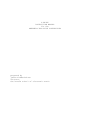
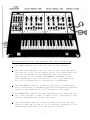
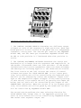
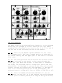
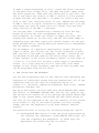
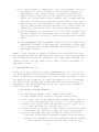
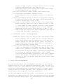
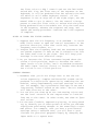
Oberheim Two-Voice
Instruction Manual &
SEM 1A Schematics
instruction manual prepared by James Michmerhuizen
cover design & conceptional layout by bluesynths.com
A BRIEF
INSTRUCTION MANUAL
for the
OBERHEIM TWO-VOICE SYNTHESIZER
prepared by
james michmerhuizen
director,
the boston school of electronic music
GETTING FAMILIAR WITH THE OBERHEIM TWO-VOICE SYNTHESIZER
1: The POWER SWITCH is at the top left of the cabinet.
2: The 2ND-VOICE SWITCH is at the left of the keyboard. When
the switch is off, voice module two will be gated when any
one key is pressed on the keyboard (but see also the
description of the VOLTAGE ASSIGNMENT SWTTCHES in the
mini-sequencer); when the switch is on, voice module two
will not be gated until a second key is depressed.
3: The PORTAMENTO control, normally left fully counterclockwise, introduces a lengthening pitch slide between different
notes on the keyboard as it is rotated to the right.
4: The TRANSPOSE control switches the keyboard voltage one volt
at a time through a range of three volts, resulting in oneoctave transpositions of the two VCO's.
5: The PITCH BEND control, normally centered, bends the keyboard voltage up or down as it is rotated, producing a corresponding pitch bend from the two oscillators.
1
The MINI-SEQUENCER is described separately on a following page.
So are the VOICE MODULES; the controls of each module are identical to those of the other, the only difference between them
being in the way they are controlled by the keyboard and
sequencer modules.
The OUTPUT MIXER consists of only three rotary pots and two
phone jacks. The Jack connections are shown in the diagram, and
the pots are:
6: the OUTPUT LEVEL CONTROL for voice module one,
7: the OUTPUT LEVEL CONTROL for voice module two, and
8: the MASTER OUTPUT CONTROL for the synthesizer.
SETTING THE STAGE
Before connecting your Oberheim synthesizer to headphones or to
an amplifier, be sure that the master output control is fully
off (counterclockwise).
After making the external connection to headphones or amplifier, you may turn the synthesizer on. Locate the ASSIGNMENTS
switches in the minisequencer section, and be sure that they
are all down.
In each voice module, set the controls to the positions shown
on the following page by the asterisks; where there is no
asterisk use the position in the photograph itself.
You may now turn, if you want to, directly to the section
called "FIRST STEPS" and begin to explore the synthesizer. But
it would probably be better to spend just a few minutes reading
through the descriptions of the minisequencer and the voice
modules first.
On the other hand, it would be a mistake to try to memorize in
detail everything in the descriptions following; they contain
some important facts--usually in italics--and some less important but still useful information. Some of this will become
familiar to you simply from habit as you work with the synthesizer.
2
THE MINI-SEQUENCER AND SAMPLE/HOLD.
1. The CONTROL VOLTAGE PRESETS determine two different output
voltages at each of the sequencer's eight positions. Each numbered position in this section of the panel has two independent
concentric rotary pots. The outside pot controls the SEQUENCE
OUTPUT ONE, and the inner pot determines SEQUENCE OUTPUT TWO.
An LED at each position is illuminated when that position is
active.
2. The VOLTAGE ASSIGNMENT SWITCHES determine the source and
destination of voltages from the sequencer and sample/hold. In
the module illustrated there are four switches. In the module
included with the 2-voice synthesizer there are three switches;
the description following applies to the three-switch version.
The first switch on the left selects the source of control
voltages and gates for VOICE MODULE ONE. In its lowest position, voice module one will be controlled by the keyboard only,
and will not be affected by either the sequencer output voltages or the sample/hold output voltages. In the center position
of this switch, voice module one will be gated by the CLOCK (#5
below) and its VCO's will be controlled by the output of the
SAMPLE/HOLD (#4 below). When the switch is in its highest position, voice module one will be gated by the CLOCK and its VCO's
will be controlled by SEQUENCE OUTPUT ONE.
The second switch performs the same selecting function for
VOICE MODULE TWO, except that in its uppermost position the
VCO's in voice module two will be controlled by SEQUENCE OUTPUT
TWO rather than sequence output one.
3
The third switch allows either KEYBOARD VOLTAGE ONE or KEYBOARD
VOLTAGE TWO to be added, respectively, to either SEQUENCE OUTPUT ONE or SEQUENCER OUTPUT TWO. Thus one of the keyboard voltage outputs may be used to transpose a sequence from one note
to another without affecting the pitches produced by the other
voltage in controlling the other voice module.
3. The SEQUENCE LENGTH switch is used to shorten a full eightstep sequence down to anywhere from seven steps to only one.
When this switch, for example, is set to "7", the sequencer
will count through positions 1-7 and then skip the 8th step,
starting over instead from position 1. This is useful in setting odd or asymmetrical rhythms.
4. The two rotary pots in this section of the panel determine
respectively the RANGE covered by the sample/hold output voltage, and the amount of LAG (low-frequency filtering) applied
to the sample/hold voltage. Turning the lag control to the
right produces, in other words, the same effect on pitches
being governed by the sample/hold, that the PORTAMENTO control
produces on pitches being governed by the keyboard.
5. This is the MASTER CLOCK that steps the sequencer and operates the sample/hold. The rotary knob determines the frequency
of this clock--i.e. the stepping rate or tempo. The three-position switch turns the clock on and off; it can also be clicked
momentarily down to advance the sequencer one step or to cause
a new sample voltage to be taken.
A switch is incorporated into the clock tempo control, allowing
the knob to be pulled out from the panel. In this position, the
clock rate will be controlled by SEQUENCER OUTPUT TWO. This
voltage control of the clock frequency is also affected by the
third VOLTAGE ASSIGNMENT SWITCH: in its uppermost position (#2
above), the keyboard voltage is added to sequencer output two
and will therefore also determine the clock rate.
4
THE VOICE MODULES
The panel controls on each module are identical. In the diagram
above they are grouped by similar functions for easy understanding. The asterisks in sections la, 2a, 3, 4, 7, 8, and 10
are for use in the following section of the manual.
la, 2a. These are the MANUAL TUNING CONTROLS for VCO 1 and
VCO 2 respectively. The lower flanged portion of each knob is
for coarse tuning, and the upper part of the knob is a vernier
fine tuner.
lb, 2b. The three-position switch selects one of three control
signals, indicated on the panel, to be routed through the
rotary pot just above the switch. If this knob is rotated to
the right, the selected control voltage will affect the VCO
pulse width. If this knob is rotated to the left, the selected
control voltage will affect the VCO frequency. If the knob is
left in its vertical position (as in the photograph), the
selected control voltage will have no effect on the VCO at all.
1c, 2c. These are MANUAL PULSE WIDTH CONTROLS for the two
oscillators. At vertical, as in the diagram, the pulse produced
in each cycle is exactly one-half as long as the cycle itself;
5
such a signal is called a square wave. As the knob is rotated
in either direction from vertical, the pulse becomes wider (to
the right) or narrower (left).
3. When this switch is
NIZED to the frequency
switch regardless; but
produce only harmonics
When the switch is off
pendent.
moved to the right, VCO 2 is SYNCHROof VCO 1. VCO 1 is not affected by this
VCO 2, when it is "sync'd" to VCO 1, can
of the frequency to which VCO 1 is set.
the two oscillators are completely inde-
4. These are the three MANUAL CONTROLS for the filter. The
smaller knob at the lower right determines whether the filter
will act as a bandpass filter (at the click-stop position
labelled "BP"), lowpass filter (immediately clockwise from the
click-stop, labelled "LP"), notch filter (vertical, at the word
"notch"), or highpass filter (extreme clockwise, labelled
"HP"). Do not try to turn the knob clockwise past the highpass
stop.
The large vernier control at the upper left determines the frequency at which the filter begins to take effect, or the center
frequency of the bandpass and notch modes. In the low- and
high- pass modes the frequency at which the filter begins to
have some effect on a signal passing through it is called the
cutoff frequency of the filter.
The large single knob labelled RESONANCE determines the filter
resonance at its cutoff frequency. When this knob is fully
counterclockwise the filter resonance is at a minimum; as it is
rotated to the right the resonance increases. RESONANCE is a
term for the gain (i.e. roughly, loudness) of the filter at or
near its cutoff frequency. At maximum resonance, for example,
the filter amplifies strongly any components of the input signal that lie within a semitone or so of the cutoff frequency,
but virtually ignores components that are not near the cutoff
frequency.
In other words, a pronounced "peak" occurs in the filter frequency response as the resonance is increased, which grows
higher in amplitude as it grows narrower in width. When the
center of this peak is exactly at the frequency of an audio
input to the filter, a relatively weak signal can drive the
filter to produce a quite strong output.
5. The switch selects one of three sources for a control input
to the filter. The left and right positions are self-explanatory; the center position carries a signal from the SAMPLE/HOLD
section of the mini-sequencer panel. This signal is independent
of any of the routing and assignment switches in the
6
mini-sequencer. The knob is a "reversible attenuator" for the
control signal selected; in the photographed position, no signal will pass through to have any effect on the VCF CUTOFF FREQUENCY. As the knob is rotated to the right, the selected
control signal affects the VCF directly; as the knob is rotated
to the left, the signal affects the VCF inversely, i.e. a positive voltage drives the VCF frequency down rather than up.
6. These are the AUDIO INPUT SELECTOR/ATTENUATORS for the VCF.
In the photographed position, they are all OFF. Unless at least
one of these is "open", i.e. rotated either to left or to
right, the module will produce no sound regardless of any of
the other settings anywhere on the module panel.
The first knob on the left, labelled "VCO 1", selects either
the sawtooth (leftwards) or pulse (rightwards) signal from VCO
1 as an audio input to the VCF. The second one does the same
for signals from VCO 2. The left side of the third knob is not
connected to any signal (except that for the first VOICE MODULE
there is a Jack at the back of the synthesizer for an external
audio signal input, and this jack is wired to the left position
of the knob on module one); the right side is wired directly to
the output of the NOISE GENERATOR that is part of the sample/
hold in the minisequencer. Noise, filtered in various ways, is
used in the production of wind, thunder, and motor sounds, as
well as many percussion effects.
Signals from the two oscillators and the noise generator may be
mixed in various proportions by opening all three of the input
attenuators at the same time.
7. These three rotary pots determine the behavior of ENVELOPE
GENERATOR ONE. The first two knobs set two time constants: the
attack time constant is the amount of time required for the ENV
1 OUTPUT VOLTAGE to rise from 0 to maximum, and the decay time
constant is the amount of time required for the ENV 1 OUTPUT
VOLTAGE to fall...
...from maximum to the level set by the third knob, and
...from this sustain level back to 0.
The third knob determines, not a time constant, but a voltage
constant. This constant is the level at which the ENV I output
will be sustained (hence the label) for as long as a GATE signal is present at the gate input of the envelope generator.
GATE signals may originate either from the keyboard or from the
MASTER CLOCK in the minisequencer. They act as "begin-end"
instructions to the envelope generators; on the appearance of a
gate signal at its input, an envelope generator commences an
ATTACK-DECAY-SUSTAIN---cycle, and when the gate signal ends,
the envelope generator executes a final DECAY as described
7
above. Gates are thus members of the general class of TIMING
signals; other timing signals are TRIGGERS. The Oberheim
2-voice synthesizer does not use trigger signals.
8. These three knobs set the constants attack time, decay time,
and sustain voltage level for ENV 2.
NOTE: as you can determine by examining the control voltage
select switches for the two VCO's and the VCF, ENV I can be
used to control VC0 1, and ENV 2 can be used to control VCO 2
andlor the VCF. in ordinary keyboard use, i.e. without special
effects, ENV I will be used only to control the VCA, and ENV 2
will be used only to control the VCF.
9. Each voice module contains a LOW-FREQUENCY OSCILLATOR. The
output of this oscillator is a sine wave and is available to
control the VCO's and/or the VCF through the voltage select
switches described under #lb, 2b, and 5. The actual frequency
of the LFO is set by the knob indicated here.
10. Normally the VCA is controlled by ENV 1 (see NOTE above).
In order to simplify the operation of the voice module while
learning, or whenever it is necessary to hear continuous sound,
this VCA BYPASS SWITCH can be moved to the on (right) position.
This disconnects ENV 1 from the VCA control input and leaves
the VCA permanently wide open so that signals pass through it
completely unaffected; in effect, the VCA is "bypassed." Moving
the switch to the left closes the VCA again and reinstates the
control voltage from ENV 1.
11. This light indicates the presence of a GATE signal (see #7
above) at the input to the two ENVELOPE GENERATORS. Press a
key; depending on the position of the 2ND-VOICE switch at the
left of the keyboard, one or both of the indicator lights will
go on.
NOTE: Even before hearing any sound from the synthesizer, you
can use these indicator lights to understand the function of
the VOLTAGE ASSIGNMENT SWITCHES (minisequencer #2). Move the
two left switches up to the SIH position, and press a key or
two; note that the lights do not now go on. Start the CLOCK
(minisequencer #5) and note that they go on and off regularly
at a rate that increases as the clock frequency increases.
8
FIRST STEPS
A. CONTINUOUS SOUND
Begin by setting all the controls on VOICE MODULE ONE to the
positions indicated in the diagram/photograph on page five,
except for #1a, 2a, 3, 4, 7, 8, and 10, which should be set to
the positions indicated by the asterisks.
Open the MASTER OUTPUT LEVEL control to about two-thirds.
Open the OUTPUT LEVEL CONTROL for voice module one about
two-thirds.
Now opening any one or more of the AUDIO INPUT SELECTORS (#6)
in voice module one will allow you to hear a signal from the
corresponding signal source. Listen to each of the VCO signals,
and to the noise generator (the third knob, rotated clockwise
from center, brings in the noise generator).
Experiment with various tunings of the two oscillators relative
to each other; with the keyboard and its controls; with the
manual pulse-width controls of each oscillator (note that these
have no effect on the sawtooth oscillator outputs); and finally
with the VCF manual controls for frequency, resonance, and pass
mode.
Do not at this time experiment with the controls numbered lb,
2b, or 5.
NOTE: You should pay particularly careful attention to the way
the three VCF manual controls interact with each other. For
examples---IF the frequency setting is low (left) and
--IF the mode is lowpass (LP), THEN
no signal will pass through the VCF even when all audio
inputs are open.
Conversely,
-- IF the frequency setting is high, and
-- IF the mode is highpass (HP), THEN
you will hear nothing, or very little, even though all the
audio inputs are open.
B. VOLTAGE CONTROL OF THE OSCILLATORS AND THE VCF
Listening only to the pulse output of VCO 1, and with the filter settings as given on page five, examine the switch and knob
in section lb of the panel. As long as the knob is centered
vertically, the position of the switch makes no difference.
9
Now move the switch to the right. This selects, as a control
signal, the output of the LFO. Rotate the knob to the left; you
will hear the pitch rise and fall, further in each direction as
the knob is rotated further to the left. The rate (i.e. speed
or frequency) of this rise and fall is directly determined by
the frequency of the LFO itself; and you can change that with
the knob #9 in the diagram.
After you have experimented with this for a while, return the
controls to the settings of page five.
Now open the input from the noise generator; switch the VCF to
bandpass operation; set the resonance about one-third; and
raise the frequency of the VCF to about 1 o'clock position. You
should hear something like whistling wind.
The control voltage selector and attenuator for the VCF are in
section #5. Move the switch to the right, and the attenuator to
either right or left. The approximate "pitch" of the whistling
wind will rise and fall under control of the LFO.
NOTE: The VCF cannot generate signals of its own. It can only
change the balance of different frequency components present in
the audio signal given to it. When you change the VCF "frequency" setting, either manually or by voltage control, you are
changing the "range" or "area" of particular frequencies that
are emphasized. Try using maximum resonance with a lowpitched
sawtooth input open only a little--about 10 o'clock--and manually sweeping the VCF frequency from bottom to top slowly. You
should be able to hear individual harmonics of the sawtooth
very easily. Return to the "whistling wind" setup for the next
step.
Now move the control selector switch to the left, providing ENV
2 as the control signal, and rotate the signal attenuator to
the right about halfway open (3 o'clock'position). Depress any
key on the keyboard, and hold it down. You will hear the area
of emphasized frequencies in the noise--the "whistling"--rise
and fall again. Continue these experiments with different settings of the ENV 2 attack, decay, and sustain constants, until
you are thoroughly familiar with them. Then leave the settings
unchanged at the positions of the diagram on page five, while
you press a key repeatedly; each time lowering the VCF frequency setting a little, and increasing the control signal
amplitude by rotating the knob a little further to the right.
Now try an oscillator signal instead of the noise generator
input signal. Drop the resonance to minimum and use the lowpass
mode. The settings you have now arrived it provide one way of
interrupting the continuous sounds you have been hearing up to
10
now, so that the synthesizer "produces" a sound only when you
have pressed a key. Experiment with various settings of the ENV
2 controls, and with setting various relationships between the
VCF frequency control and the knob (#5) that determines control
signal amplitude.
NOTE: These relationships are the most crucial ones in the synthesizer; until they are mastered, you will not be getting
the most that you can from your instrument. A quick summary
of the most important points to learn: (verify each one as
you read.)
a) in many keyboard setups the filter is either closed, to
open only under control of ENV 2, or (less often) open,
to be closed only under control of ENV 2.
b) a highpass filter is closed when its frequency is high; a
lowpass filter is closed when its frequency is low; a
bandpass filter is closed when its frequency is either
high or low; and a notch filter is always open.
c) when the control input attenuator is rotated left, the
incoming signal from ENV 2 drives the filter frequency
down; as it is rotated to the right, the ENV 2 signal
drives the filter frequency up.
d) as the filter resonance is increased, its output level
will--generally--increase. Compensate by lowering
slightly the level of the input audio level. At maximum
resonance a very small input signal is enough to produce
full output from the filter (in a very narrow band of
frequencies).
C. INTERRUPTED SOUND
If the filter manual frequency setting is at minimum, and the
mode control is set for lowpass operation, and the control
input attenuator is at maximum right, the filter alone will be
capable of producing "events" under keyboard control. In other
words, with these settings you will hear nothing until a key is
depressed, thus gating the ENV 2 "on" which opens the filter to
allow a signal to pass through.
In many cases, however, you will want to use the filter for
some other purpose--perhaps controlled by the LFO, or even not
controlled at all except manually. Good oboe and bassoon timbres, for example, require a resonant filter at a constant frequency.
In all of these cases, you will need to use the VCA to interrupt the continuous source sound and produce "events."
11
To make a simple beginning at this, return the filter settings
to the positions of page five, and open the audio input from
the noise generator. Then move the switch #10 to the left. The
VCA is now under the control of ENV 1, and will allow signals
to pass through only when ENV 1 is gated on. Press a key and
hold it until the resulting event is over. Change the settings
on ENV I and do it again; continue to experiment until you can
anticipate the kind of event that will result from any arbitrary setting of the ENV 1 constants.
You can gate ENV 1 automatically--instead of from the keyboard--by moving the left assignments switch in the
mini-sequencer to either its middle or upper position, and
turning the CLOCK on. Do this now, and set the CLOCK tempo to
something near one beat (gate) per second. Events are now produced automatically, leaving both your hands free to manipulate
the VCF manual controls.
For an example of a practical application, reduce the noise
input to about two o'clock, set the filter resonance to maximum, and the filter mode to bandpass. The ENV 1 should be set
for minimum attack and sustain and fairly short decay. Now
slight changes in the filter frequency control in the range 12
o'clock to 3 O'clock will produce a wide range of percussive
noises. In a later section you will learn that even these
changes in the filter frequency need not be done by hand, but
can be programed from the s/h unit.
D. TWO VOICES AND THE KEYBOARD
You are now acquainted with all the controls that determine the
character of individual events from the synthesizer. All of the
remaining controls are used for producing chains of
events--i.e. melodies, repeating sequences, bass lines, random
percussive rhythms, etc.
But up to this point you have used only VOICE MODULE ONE, under
the control of KEYBOARD VOLTAGE ONE. You are now ready to use
the second voice module; do so by opening the OUTPUT LEVEL CONTROL in the output mixer, and moving the 2ND VOICE switch at
the left of the keyboard to ON. Set the controls on the second
voice module to any of the useful patches you have already
found, and use the keyboard to play both modules simultaneously.
You should be able to verify the following "keyboard logic":
a) VOICE MODULE ONE always follows the pitch represented by
the leftmost key depressed. VOICE MODULE TWO always follows the rightmost key depressed. If three keys are
depressed, the middle key has no effect.
12
b) If only one key is depressed, only voice module one will
be gated; if, while one key is held down, another is
depressed to the right of the one that is being held
down, voice module two will be gated on with the new
note; if, on the other hand, another key is depressed to
the left of the key already being held down, then voice
module one will be assigned to the lower key--thus moving to a new pitch-and voice module two will be given the
upper key; both voices will be gated simultaneously.
c) Legato playing on the second voice will not produce new
pitches unless the 2ND VOICE switch is OFF. Legato playing on the first voice will produce new pitches regardless.
d) The PORTAMENTO and PITCH BEND controls do not affect both
keyboard voltages in the same way, and exactly what they
do to the second voltage depends on the position of the
2ND VOICE switch.
NOTE: a vast number of special effects are possible with various configurations of the keyboard controls. The most ordinary
and conservative results, however, will come from playing continuous legato on the lower voice, and a slight nonlegato on
the upper voice.
E. TROUBLESHOOTING (I)
Using only the controls we have introduced so far, it is--as
you have probably discovered already--possible to reach situations in which you are momentarily lost, either because you are
not getting any sound at all when you press a key, or because
you can't seem to make the sound shut off even when no key is
depressed. The following checklist will review the things to
look for in both cases.
1. NO SOUND: (EITHER MODULE)
- is the master output level open wide enough?
- is the output level control for the module open?
- is at least one of the module audio inputs open? (See p.
five and the description of area 6 in the diagram.)
- is the filter open? (See the definitions of "open" on p.
11, and the note in italics on p. 9.)
- if the filter is closed, is the setup of the switch and
attenuator #5 such as to open it with an envelope?
- certain envelope settings of the two generators will
interact to prevent an audible output from leaving a
module; for example, a short attack and decay on ENV
1, min. sustain (controlling the VCA) with a long
13
-
-
-
attack on ENV 2 controlling the filter from a closed
lowpass configuration: the VCA will be
open-and-closed again before any significant output
is developed from the filter.
are the oscillators tuned higher than audibility?
is the proper assignment switch--in the
mini-sequencer--set to keyboard control of the module?
if the assignment switch is not set to keyboard control,
is the clock on or off? (No gates can be produced, of
course, unless the clock is on.)
how high is the sustain level on ENV 1? In legato keyboard playing, when the VCA is under control of ENV
1, there must be some sustain voltage or the output
of the module will disappear more or less rapidly,
depending on the decay time setting of ENV 1. The
same holds for the filter when its manual setting is
closed and only ENV 2 opens it.
2. CONTINUOUS SOUND: (EITHER MODULE)
- there are really only two ways to get continuous sound
from a module; one of them you are already familiar
with since that's how we started you off: the VCA
BYPASS switch on, and the filter open. If either of
these conditions does not hold then no continuous
sound is possible, except that
- with certain envelope settings, under gating from the
clock, an extremely high tempo setting of the clock
control will produce virtually continuous sound simply because of the high tempo. (Imagine playing notes
on a piano as rapidly as possible, like a mandolin-"continuous sound".) Naturally this can't happen
unless the proper assignment switch on the minisequencer is set for gating from the clock rather than
the keyboard.
F. USING THE MINISEQUENCER
As you already know, the ASSIGNMENTS switches in the minisequencer section of your Oberheim synthesizer must be down in
order to play the voice modules from the keyboard. In the down
position, each module gets a keyboard control voltage, which
controls the oscillator pitches, and a keyboard gate signal,
which starts and stops the envelope generators.
If the assignment switch for either voice module is in either
the middle or upper position, both the keyboard control voltage
and the keyboard gate signal are disconnected from the module
14
and can have no effect on its behavior. Instead, the envelope
generators for the module will get their gate signals from the
CLOCK in the minisequencer--you already are familiar with this
from paragraph two on page twelve--and the oscillators will get
their control voltages from either the S/H unit or from the
8-step sequencer, depending on the center or upper position of
the assignment switch.
Now move the assignment switch for voice module one to its
upper position, labelled SEQ 1. Move the switch in the CLOCK
section of the minisequencer to its upper position, labelled
"run". The gate light in voice module one should immediately
start blinking (more or less rapidly depending on the chance
frequency setting of the CLOCK), and a series of events of different pitches should be produced from voice module one. If you
hear nothing, see the preceding section E.1 of this manual.
Note that at each new pitch, a new position light illuminates
on the minisequencer. In order to change the pitch produced at
any particular step, stop the clock on that particular step and
open the signal path so as to get continuous sound. Then use
the CONTROL VOLTAGE PRESET at that position to change the pitch
of the oscillator.
The on-off switch for the minisequencer CLOCK has also a lower
position labelled step. This position is spring-loaded and the
svitcb will not stay there; but every time you push it down,
the sequencer will advance to the next step in the sequence.
This enables you to set an entire 8-step sequence rapidly and
easily.
When you have set up a sequence that you like, try playing
voice module two from the keyboard along with you sequence.
NOTE: if you find that you can't get any sound out of the second voice, check the 2ND VOICE switch At the left of the keyboard. It should be OFF. (If it is ON, you will have to press
two keys in order to get a gate for the second voice--remember?)
Now voice module two will be controlled by the sequencer if the
second ASSIGNMM switch is set to the SEQ 2 position. A second
set of control voltages is available from the sequencer CONTROL
VOLTAGE PRESETS, so that the pitches produced by the second
voice can be set independently of those produced by the first
voice; the inner knob at each sequencer position determines the
SEQ 2 voltages.
NOTE: Many beginners find some difficulty in tuning to familiar
pitches and intervals because of the continuously variable tuning controls. At the end of this manual, under the heading
"PERFORMING HINTS," we will give some simple aids to tuning
under various circumstances.
15
Through all of your experiments so far with the minisequencer,
the third ASSIGNMENTS switch should have been down.
Now move it to its center position, labelled SEQ 1 By CV 1. In
this position, KEYBOARD CONTROL VOLTAGE #1 is reintroduced to
the control inputs of the VCO's in voice module one. Try it;
you will find that the keyboard can now TRANSPOSE any sequence
being produced by voice module one. All of the keyboard controls themselves--portamento, pitch bend, the transpose
switch--are effective. If both modules are under sequencer control, you will find that the pitches produced from the second
voice module are, however, not affected by the keyboard.
It should not be hard to guess that in the SEQ 2 BY CV 2 position, the sequencer output voltage to the second voice module
will be transposed by KEYBOARD CONTROL VOLTAGE #2. The first
voice will not be affected by anything you do at the keyboard.
Since, however, the 2ND VOICE switch plays a role in determining when and how a second control voltage is produced from the
keyboard, it will also affect the transpositions of SEQ 2. For
example-a) if the switch is off, transpositions will occur with the
depression of only a single key; if one key is held down
while another is depressed to the right of it, the
sequence will transpose to the higher key only for as
long as the higher key is depressed. When the key is
released the sequence will transpose down again to the
pitch of the lower depressed key.
b) If the switch is on, one-key-at-a-time playing will not
transpose the sequence; but if one key is held down, and
another is pressed to the right of it, the sequence will
transpose and will hold the transposition after the second key is lifted. No further transposition will occur
until the next occasion on which two keys are depressed.
NOTE: The latter setup gives you considerable performing freedom in controlling voice one from the keyboard. A sequence
transposition can be established for voice two by pressing two
keys; after that you have the full freedom of the keyboard for
playing voice one. But you must develop a non-legato touch; any
overlapping of keys will be interpreted INSTANTLY by the keyboard electronics as a transpose instruction for the second
voice sequence.
This use of a non-legato playing technique does not mean, of
course, that you cannot have legato phrasing; that will be
determined by the decay time on your envelope generators, not
by your keyboard touch.
16
Finally, you should experiment with the control of the CLOCK
itself by SEQ 2. This is accomplished, as the panel indicates,
by pulling the clock frequency control knob out from the panel
about a quarter-inch. Do that; notice that the stepping rate
suddenly becomes irregular, but forms repeating patterns every
eight steps. Now the length of any one step will be determined
by the SEQ 2 CONTROL VOLTAGE PRESET for that step. Use the presets to set up a regular rhythm; the clock frequency control
will determine the overall tempo.
NOTE: Since, when the SEQUENCER TRANSPOSE switch is at the SEQ
2 BY CV 2 position, the keyboard second control voltage is
added to the voltage output of SEQ 2, then when the CLOCK frequency is being controlled by SEQ 2, the frequency will also be
determined by the keyboard. IN OTHER WORDS, this setting gives
you keyboard control of a sequencer tempo!
G. THE SAMPLE AND HOLD UNIT
The control voltages produced by SEQ 1 and SEQ 2 are programmed
at each step by the performer. Voltages from the SAMPLE/HOLD
unit are random. Listen to voice one under control of the s/h;
begin with the two knobs in the s/h section rotated maximum
counterclockvise, and slowly increase the range setting. The
first voice produces a series of random pitches over a wider
and wider range as the knob is rotated further to the right.
The lag knob introduces a portamento into the pitch
changes--longer as it is rotated to the right. Try it.
The middle position of the VCF control selector, labelled
"EXT", carries a 9/h voltage to control the filter. Try using a
noise input to the filter, open only to about two o'clock, and
set the filter to bandpass operation at maximum resonance. Use
a short percussive envelope on the VCA and adjust the VCF frequency to about the middle of its range or a little higher.
Open the control input attenuator on the filter while the s/h
is running. You should hear a series of percussive events of
various noise colors. Remember doing this by hand back at page
twelve?
You can introduce accents into the series by lengthening the
decay time on the VCA envelope: try it. Make the patch more
complex by setting up the keyboard-control-of-tempo effect you
learned in the preceding section.
H. PERFORMING HINTS
You have now learned something about each of the functions in
the Oberheim 2-voice synthesizer, and something of how each
17
control interacts with the others to produce a wide range of
sounds. Continuing practice will make you fluent in moving from
one sound to another quickly and accurately. In the meantime,
here are some hints to help you achieve this sooner.
TUNING AIDS
1. In tuning the oscillators, it helps to leave the VCF and
VCA open--that way you don't have to keep striking a key
as if you were tuning a guitar or piano.
2. To tune a module to concert, or "standard" pitch, set the
keyboard TRANSPOSE switch to 8' and depress the middle A
while you tune one oscillator to your external pitch
source. Then release the A. The second VCO can be tuned
to the first; use sawtooth waves for all tuning procedures.
3. Tune only two oscillators at a time, using the same
oscillator as your reference each time. For example,
make VCO I in the first module your reference; then after
you have tuned VCO 2, close the audio from VCO 2 and open
VCO 1 in the second module and tune it, and finally close
that input and open the one from VCO 2 in the second module and tune VCO 2. Then open all four to check.
4. The beat frequency will always double as you go up by
octaves. So after you have tuned at 8', go up to 4' and
then 2' to check on the tuning of each oscillator; readjust if necessary. If you ever find that an oscillator
seems to go out of tune as you go down again, you may
need to calibrate it.
5. It is generally useful to tune the two VCO's in a single
module to some interval other than unison. Try octaves,
twelfths, fifteenths, and other harmonic intervals
within a three-octave range. Drop the level of the
higher VCO when tuning; it will make the beats more audible.
6. You needn't attempt to get the beat frequency actually
down to ZERO. "Zero-beat" is an approximate phrase for
anything less than one beat every second or two. In many
cases you will actually want the slight "singing" quality produced by this slow beating--this is literally a
phasing effect. (Use two sawtooth waves in unison and
play them through short-decay percussive envelopes: listen to the color changes as the two signals go in and out
of phase.)
7. SETTING PITCHES IN A SEQUENCE. Suppose that you want to
set a pitch sequence for VOICE ONE under the control of
SEQ 1. With both modules open, and assuming they have
already been tuned to unison from the keyboard, switch
18
the first voice to SEQ 1 control and set the 2ND VOICE
switch OFF. Play the first note of the sequence on the
keyboard; it will be produced from the second voice module which is still under keyboard control. (If the
sequencer is not at step one of the eight steps, use the
manual STEP to get it there.) Use the control voltage
preset to tune the first voice to unison with the pitch
being produced from voice module two. Play the next note
in the sequence, advance the sequence one step, and
repeat the tuning procedure. Continue until the sequence
is complete.
RULES OF THUMB FOR FILTER CONTROL
1. Suppose that the VCF frequency is at maximum.. It would
make little sense to open the control attenuator in the
positive direction, since that could only increase the
frequency even further, so...
2. Imagine that the frequency knob and the attenuator knob
are geared together so that as one is turned to the left
the other must turn to the right. This will keep your
settings in the most effective range.
3. As you increase the filter resonance beyond about the
eleven o'clock position, begin to decrease the audio
input levels to the filter, until at maximum resonance
the audio input level(s) is(are) no further than about
ten o'clock or two o'clock position.
GENERAL REMARKS
1. Remember that you do not always have to use the two
voices separately. Complex and beautiful sounds can be
produced in single-voice operation by combining the two
modules, using complementary envelope settings on each
one. For example, use a percussive envelope on one and a
long-attack, "bowed" attack on the other. The two sounds
will fade from one to the other.
2. You can also set them up as two contrasting voices and
use the level controls on the output mixer to "switch"
from one to the other. In other words, use them as "preset" voices.
3. For the most flexible, expressive playing, in every patch
try to identify two or three points at which you can make
significant performing changes in the sound with a minimum effort. For example, once you have a good "brass"
envelope using a sawtooth wave, you will have a good
clarinet for practical purposes simply by changing the
input audio to a square wave.
19
SEM 1A
Schematics
Envelope Generators
LFO
VCOs
VCF
VCA
NOTES
POWER SUPPLY
ONBOARD REGULATOR
TRIMMER LOCATION
WIRING HARNESS
conceptional layout by
bluesynths.com