1
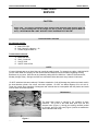
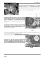
8950, 8960, and 8990 Series
Service Manual
FORM 5579-1
8900 HIGH PERFORMANCE TIRE CHANGER
SERVICE MANUAL
CHAPTER 1
INTRODUCTION AND OPERATION
General Operation
The 8900 Series High Performance Tire Changers are air/electric units, incorporating pneumatic and
electrical systems in the same unit to mount, demount, seat beads, and inflate tires. The motor used in
domestic applications is a 1hp/115volt/60Hz reversible, capacitor start motor, designed for continuous
duty and is controlled by a bi-directional 42-ampere barrel switch. Machines destined for the
International market may have other power requirements, depending on the location it is going to. The
motor drives a worm shaft, which drives a worm gear in the transmission (located below the turntable,
inside the base weldment). This rotates the turntable forward and backward. Bead breaking with the
8900 series tire changer is accomplished using a double acting pneumatic cylinder with no return spring.
Rims are clamped using two synchronized cylinders. This evenly distributes force to four clamping jaws.
Clamping may be done either from the outside of the rim inward, or from the inside of the rim outward,
depending on what the situation requires. Bead seater jets are attached to the clamp jaws to allow more
efficient air penetration into the tire during the bead seating stage of inflation. The major differences
between these units and other similar units (European Rim Clamp tire changers) are the availability of an
integral safety restraint system (standard) and the built in fully pneumatic pressure limiter that limits
inflation pressure in a tire to a maximum of 60 psi. By making these safety items standard on the
machines available to the public, the John Bean Company European-style tire changer is both more
functional and safer to use than those of the competition.
Unique Characteristics
The turntable is plated with a composite silver-gold-zinc plating, which is more resistant to corrosion than
similar items plated with silver-zinc only. A 1/100 ratio worm geared transmission is used on these units
for decreased noise and to enhance life expectancy. The bead breaker cylinder is a steel barrel lined
with an extra smooth acetal resin liner. This makes operation of the bead breaker quite smooth, being
nearly frictionless in operation. The use of an acetal resin liner; however, does limit the types of
lubricants that can be used in the air system to specific non-reactive types, generally plain oils without
addition of excessive detergents or additives. The bead breaker cylinder piston is machined aluminum.
Rim clamping is accomplished using twin double-acting cylinders, which are equipped with long life
piston seals. The air distribution manifold (under the turntable) and all valves are made of a special
plastic blend. The pneumatic pressure limiter is a self-contained series of diaphragms which are used to
check relative pressure of the air being supplied to the inflation hose, and compare it to the air pressure
in the tire. Maximum tire inflation possible with this system is 60psi.
Effective
3/02
Page 1-1
8900 HIGH PERFORMANCE TIRE CHANGER
SERVICE MANUAL
To understand how to service this machine please study the pneumatic schematic for information
concerning the air system and the electrical schematic for information concerning the electrical system
not yet available at the time of this printing). Other information will relate to the parts references for the
two machines.
Manufacturing Variances based on Model Number
8950 Series: Swing arm unit, capable of handling tires to 12” width, 40” OD
8960 Series: Swing arm unit, capable of handling tires to 15” width, 50” OD
8990 Series: Racing / High performance unit. Pneumatic tilt tower, capable of handling tires to 15” width, 40”
OD. Incorporates an oversized turntable for performance diameter tires. Turntable speed is variable via
mechanical means.
Page 1-2
Effective
3/02
8900 HIGH PERFORMANCE TIRE CHANGER
SERVICE MANUAL
CHAPTER 2
SERVICE
CAUTION :
1. Be sure the unit is unplugged (power off) before attempting to service the electrical part of
these units. Use proper precautions when working with machines with moving parts (no
rings, no loose clothing that can be caught in a belt or pulley, and safety glasses MUST be
worn). NEVER WORK ON A UNIT WITHOUT FIRST BLEEDING OFF THE AIR!
Recommended Lubricants
Air lubricator system:
A. Mobil DTE Light
B. Gulf ( Chevron ) Harmony – 32
C. Texaco Regal Oil R&O 32
Transmission Lubricant:
A.
B.
C.
D.
Mobil Gear 626
Shell – Omala 68
Sun EP 1050
Gulf EP Lube HD 68
NOTE:
If proper lubricants are not on hand, they can usually be easily located. For example, by calling 1-800-662-4525
you can reach Mobil Oil company for their local authorized distributors and information regarding stocking
distributors in your area. Shell oils can be located by calling 800-231-6950 from 7 AM to 5 PM Central time,
Monday through Friday. Grainger and NSC are nationwide chains that stock many brands of lubricants.
Do NOT substitute lubricants randomly! Random substitution of oils will damage the plastics and seals used in
the bead breaker cylinder, foot valves, and other cylinders. Do NOT use Marvel Mystery Oil or air tool oil.
These oils contain large quantities of detergents and solvents that are incompatible with the plastics and seals
used in these valves and cylinders.
Maintenance
The bead blast system is integral to the turntable of these
machines. Air is fed to the bead blast ports from the foot
actuated valve (Figure 1), through the rotating manifold (sealed
by O-rings), and out of the ports (Figure 2) which are attached to
each individual bead clamp.
Figure 1
Effective
3/02
Page 2-1
8900 HIGH PERFORMANCE TIRE CHANGER
SERVICE MANUAL
If the seals in the rotating manifold begin to dry out, the turntable
will squeak when turning. To lubricate these seals without
removing the turntable, activate the bead blast to blow out any
dirt or other contaminants, then pour a small amount of MOBIL
DTE LIGHT into one of the bead blast ports. Approximately 1
tablespoon of oil will be sufficient (Figure 2).
(Location of screw-in dipstick)
Figure 2
Recommended transmission lubricant is Mobil Gear Lube #626.
Lubricant level may be checked by removing the screw-in dipstick
located on the transmission. See the operator's manual or the
parts list for dipstick location. The physical location of the
transmission is shown in Figure 3. To completely fill a DRY
TRANSMISSION requires approximately 2 cups (16 oz.) of
lubricant.
To replace the O-ring seals in the manifold or on the main shaft of
the transmission, remove the turntable and the pneumatic
clamping cylinders, remove the air hoses leading to the manifold,
and remove the top manifold. Remove the transmission.
The O-rings can then be replaced.
Figure 3
The pneumatic turntable clamping cylinders may be rebuilt individually, or replaced as the need arises. See the
parts reference exploded diagrams ( pages 3-5 and 3-6).
Drive Belt Adjustment and Replacement
To adjust the drive belt, tighten or loosen the adjustment bolts
located below the motor on the mounting bracket (Figure 4). The
belt is properly adjusted when the belt deflects approximately 1/2"
when the belt is pinched between the pulleys using moderate
pressure.
Figure 4
Page 2-2
8900 HIGH PERFORMANCE TIRE CHANGER
SERVICE MANUAL
!
PINCH HAZARD
USE EXTRA CAUTION TO AVOID PINCHED FINGERS!
OBSERVE LOCKOUT / TAGOUT PROCEDURES!
The drive belt may be removed without loosening the motor or
changing the adjustment bolt setting. Roll the old belt off of the
small (motor) pulley, hang the new belt on the large
(transmission) pulley, and roll the new belt in place (Figure 5)
Figure 5
Should the motor start capacitor or the INTERNAL switch (in the motor) fail,
the motor must be replaced or repaired at an authorized service center for
the particular motor make and model. The motor actuating switch (mounted
on the foot pedal assembly) must be replaced as a separate assembly
(Figure 6). There are no repair parts for either of these assemblies
available from the factory.
The factory can supply complete new
assemblies as required.
Figure 6
SLIDE ADJUSTMENTS
A RIM ONLY must be locked in place on the turntable during adjustments to the slide locking mechanisms. Set
the vertical slide onto the outer edge of the rim as when mounting a tire and lock in place. Loosen the jam nut on
the vertical slide lock plate stop bolt. Adjust the stop bolt until the slide retracts 0.060" to 0.075" from the rim
when locked (Figure 7 – mechanical systems, and Figures 8, 9, & 10 – pneumatic systems).
Figure 7
Figure 8
Page 2-3
8900 HIGH PERFORMANCE TIRE CHANGER
SERVICE MANUAL
Figure 9
Figure 10
NOTE:
1. Slide lock adjustments may take several tries to get within tolerance. The slides should
repositioned between adjustment attempts and relocked. Once the adjustment is correct, lock
stop bolts in place using the jam nuts. In general, the more travel the locking plate has, the more
slide will move when locked. This must be taken into account when performing adjustments on
slides.
ADJUSTMENT OF MECHANICAL COMPONENTS
1. Foot Valves: (actuator valves): adjust using the jam nut and
threaded rod or cylinder spool (Figure 11 – illustration is of
the Inflator valve / High volume dump valve actuator – other
foot valve adjustments are performed in a similar manner).
The Foot Valve Assembly may be removed from the unit
complete by tilting the machine back and removing the three
hex head machine screws from the bottom. See parts
reference for assembly
details.
Figure 11
Figure 12 (8990)
Figure 13 (8950/8960
Page 2-4
be
the
the
the
8900 HIGH PERFORMANCE TIRE CHANGER
SERVICE MANUAL
2. High volume Dump Valve: No adjustment ( clean only – Figure 12 & 13).
3. Pneumatic Slide Locking Cylinders: no adjustment of cylinders. Retraction of head is adjusted by loosening
or tightening clearances. In general, the more slack that exists in the locking plate, the more the mechanism
will retract the slide. See Figures 7 - 10 above).
4. Rim Clamp Cylinders: no adjustment.
5. Bead Blast: dependent on line air pressure to the unit – no adjustment.
6. Bead Breaker: with bead breaker fully actuated, adjust the cylinder shaft head bolt until you see the outer
fiber washer begin to compress. This adjustment prevents the plastic piston from bottoming out, and
permits application of full pressure against the bead at any bead breaker opening (Figure 14).
7. Pneumatic pressure limiter: no adjustments or replacement parts.
complete assembly (Figure 15).
If this unit is faulty, replace as a
Fully Pneumatic Pressure Limiter
Figure 14
Figure 15
8. To remove the bead breaker cylinder (Figure 16),
•
•
•
remove the air lines from the cylinder
remove the adjusting nut (on the external end of the
cylinder shaft.)
remove the pivot bolts.
The cylinder is now free to be removed from the machine.
Parts are available for the cylinder. See Drawing 3-15, for a
listing of parts.
To reinstall the bead breaker cylinder, reverse the above
steps.
Figure 16
Page 2-5
8900 HIGH PERFORMANCE TIRE CHANGER
SERVICE MANUAL
Safety Restraint Arm Adjustment
Air travels from the fully pneumatic pressure limiter through a cam operated safety valve located near
the pivot point of the safety restraint arm (Figure 19) to the inflation hose. This valve must be operational and
adjusted so air flows when the safety restraint arm is placed into an operating position.
The valve is mounted in a fixed position on the arm mount. The cam is mounted to the arm and is free to
move with it (Figure 18). To adjust the cam, loosen the hex head set screw and turn the cam to the proper
position on the pivot pin (Figure 17).
• Hex Head Set Screw
Figure 17
•Valve Cam
• Pivot Pin
•Valve
Figure 18
Figure 19
NOTE
Any time an explosion occurs on a system equipped with a safety restraint arm, the SRA assembly must be
replaced as a unit, and the rest of the tire changer closely inspected for damage
Page 2-6
8900 HIGH PERFORMANCE TIRE CHANGER
SERVICE MANUAL
IMPORTANT
Tire changers equipped with SRA devices MUST be anchored by the rear two mounting holes on the cabinet.
Failure to mount the tire changer in this manner may result in the danger of overturning in the case of an
explosion.
SERVICE TIPS
•
The Bead Breaker Arm is shipped positioned vertically to conserve space. Install the bead breaker arm in
its correct position prior to use of the machine, then install the two snap rings.
•
The Transmission Pulley is placed relatively close to the tire changer housing. To replace the pulley,
loosen the transmission mounting bolts and rotate the transmission on its shaft to allow access to and
removal of the pulley.
•
If replacement of the Lower Manifold is necessary the Bead Blaster Hose Nipple must be removed. To
remove this nipple, first disconnect the hose at the dump valve, then twist the hose in a counterclockwise
direction while it is still connected to the bead blast nipple.
•
Corrosion in the Bead Blast Dump Valve will cause air to leak through the bead blast lines. Removing the
plate on the bottom of the valve and clean the diaphragm. See Figure J in the text.
•
Replacement of the Drive Belt can be done without adjusting the motor or transmission (see Figure 5 in the
text).
•
A clogged Conical Filter within the air inlet to the tank will restrict air flow into the tank, and will cause poor
performance of the machine.
Page 2-7
USA
John Bean Company
309 Exchange Ave.
Conway, Arkansas 72032
Tel. (800) 362-8326 or (501) 450-1500
Fax (501) 450-1585
Notice: The information contained in this document is subject to change without notice. John Bean Company
makes no warranty with regard to this material. John Bean Company shall not be liable for errors contained
herein or for incidental consequential damages in connection with furnishings, performance, or use of
this material.
This document contains proprietary information which is protected by copyright and patents. All rights
are reserved. No part of this document may be photocopied, reproduced, or translated without prior written
consent of John Bean Company or its holding company.
Form 5579-1...02/18/97...
copyright 1997
Printed in the USA