1
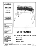
S_/A/RS
owners
manual
MODELNO.
149.236222
SERIAL
OR CODE
NUMBER:
Model and code number may be
found on the back of the base
You should record both model and
code number and re_.ain in a safe
place for fulure use
S_FAIRS/ CRAFT$IvtRN_
CALIFORNIA
OWNERS: a unique
serial code number is slamped on
the underside of !he machine
CAUTION:
Read All Instructions
Carefully
Before Start.
ing Assembly
and Use.
41_-I C
JOINTER-PLANER
= assembly
, operating
Save This Manual For
Future Reference,
• repair parts
SEARS,
Part No 4502.250-00
ROEBUCK
AND CO.
DepL 6981731A, Sears Tower,
Chicago,
IL 60684
7f90
FULL ONE.YEAR
WARRANTY
ON
CRRFTSMRN ,JOINTER
-- PLANER
If within one year from the date of purchase, this Craftsman Jointer -- Planer fails due to a defect
in material or workmanship, Sears will repair it, free of charge.
WARRANTY SERVICE IS AVAILABLE
CENTER IN THE UNITED STATES.
This warranty gives you specific
state to state°
Sears, Roebuck
BY CONTACTING
THE NEAREST SEARS STORE OR SERVICE
legal rights and you may also have other rights which
and Co. Dept. 698173tA, Sears Tower, Chicago,
vary from
IL 60684..
GENERAL SAFETY RULES FOR POWER TOOLS
1. KNOW YOUR POWER TOOL
B
For your own safety, read the owner's manual carefully
Learn its application
and limitations
as well as the specific
hazards peculiar to this tool
2 GROUNDING
cord-connected
cord.connected
tools
having a nominal
rating Jess than 150 votts:
intended
for use on a
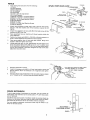
This tool is intended for use on a circuit that has an outJet
that looks like the one illustrated in Sketch A in Figure 1. The
too] has a grounding
plug that looks like the plug illustrated
in Sketch A in Figure ! A temporary adapter, which looks like
the adapter illustrated
in Sketches B and C, may be used to
connect this plug to a 2-pole receptacle
as shown in Sketch
B if a properly grounded outlet is not available. The temporary
INSTRUCTIONS
A All grounded,
Grounded,
supply circuit
tools:
In the event of a malfunction
or breakdown,
grounding
pro°
vtdes a path of ]east resistance
for electric current to reduce
the risk of electric
shock
This Iool is equipped
with an
electric cord having an equipment.grounding
conductor
and
a grounding
plug. The plug must be plugged into a matching
outlet that is properly installed and grounded in accordance
with all local codes and ordinances.
adapter should be used only until a properly grounded outlel
can be tnstatted by a qualified electrician.
The green_colored
rigid ear, lug, ete extending
from the adapter must be con..
nected to a permanent
outlet box
ground
such as a properly
grounded
Do not modify the plug provided - if it will not fit the outlet,
have the proper outlet instafled by a qualified electrician
Improper connection
can result in a risk
of the equipment-grounding
conductor
of electric
shock
The conductor
wilh
insulation having an outer surface that is green with or without yeltow stripes is the equipment-grounding
conductor
If
repair or replacement of the electric cord or plug is necessary,
do not connect the equipment-grounding
conducto_ to a live
terminal
Adapter
Check with a qualified
electrician
or serviceman
if the
grounding
instruclions
are not complelely
understood,
or if
in doubt as to whether the too] is properly grounded
The use of any Extension
(C)
Cord will cause some loss of power
To keep this Io a minimum
and to prevent overheating
and
motor burn-out, use the table below to determine
the MINI..
MUM wire size (A.WG)
Extension Cord
Figure I -- Wiring Methods
KEEP GUARDS IN PLACE
Use only 3-wire extension cords that have 3-prong grounding
plugs, and 3-pole receptacles that accept the tool's plug
_L
Extension
4 REMOVE ADJUSTING
Cord Length
25 Feet
50 Feet
100 Feet
Wire Size, A WG
16
16
14
in working order and in proper adjustment
damaged or worn cord immediately
and alignment.
KEYS AND WRENCHES
Form habit of checking
to see that keys and adjusting
wrenches are removed from tool before turning on lool
5 KEEP WORK AREA CLEAN
Cluttered
Extension Cords suitable tor use with your Joinler-Ptaner
are
available at your nearest Sears Calalog Order or Retail Store
Repair or replace
Mea_ls
6 DON'TUSE
areas and benches
invite accidents
IN DANGEROUS
ENVIRONMENT
Don't use power tools in damp or wet feeations,
them to ratn_ Keep work area well illuminated
or expose
7 KEEP CHILDREN
All visttors
18 USE RECOMMENDED
ACCESSORIES
Consult the owner's manual for recommended
AWAY
should
be kept a safe distance
from work area
Use of improper
8. MAKE WORKSHOP KID PROOF
with padlocks, master switches,
9. DON'T FORCE TOOL
It will do the job better
or by removing
starter
keys
Serious injury could occur if the tool is tipped or if the cutting
1ool is unintentionally
contacted
and be safer
at the rate for which
it
20 CHECK
10. USE RIGHT TOOL
Don't force tool or attachment
to do a job for which
it was nol
designed.
11: WEAR PROPER APPAREL
•
No loose clothing,
gloves,
neckties,
rings, bracelets,
or
jewelry to get caught in rnoving parts. Nonslip footwear Is
recommended
Wear protective
hair covering to contain long
hair
only have impact
21.. DIRECTION
Feed work
operation
resistant
is dusty
lenses
OF FEED
into a blade
LEAVE
POWER
stop
!3 SECURE WORK
PARTS
or cutter
of the blade or cutter
22 NEVER
They
are NOT safety glasses
Use clamps
DAMAGED
Before further use of the tool, a guard or other part that is
damaged should be carefully checked to ensure that ii will
operate properly and perform its intended function - check
for alignment
of moving parts, btnding of moving parts,
breakage of parts, mounting,
and any other conditions
that
may affect its-operation
A guard or other part that.is damaged
should be properly repaired or replaced.
rotation
12. ALWAYS USE SAFETY GLASSES
Also use face or dust mask if cutting
eyeglasses
accessories.
may be hazardous
19. NEVER STAND ON TOOL
was designed.
Everyday
accessories
OFF.
TOOL
against
the direction
of
only
RUNNING
UNATTENDED
Don't leave tool until
it comes
TURN
to a complete
23. WEAR EAR PROTECTION
or a vise to hold work
when practical
It's safer
than using your hand and frees both hands to operate
When operating for prolonged
tection is recommended
toot
period of time, use of ear pro-
14 DON'T OVERREACH
Keep your proper footing
15 MAINTAIN
and balance
at all times
TOOLS IN TOP CONDITION
Keep tools sharp and clean for best and safest performance
Follow instructions
for lubricating
and changing accessories
16 DISCONNECT
TOOLS FROM POWER SOURCE
before servicing
and when changing
accessories
such as
blades, bits, cutters,
or when mounting
and re.mounting
motor.
17.. AVOID ACCIDENTAL
Make sure
cord
switch
The operation
STARTING
is in *'OFF"
position
before
plugging
of any power
tool can result
in foreign
being thrown
into the eyes, which can result in
damage. A_ways wear safety goggles complying with
(shown on Package) before commencing
power tool
Safety Goggtes are available at Sears retail or catalog
in
objects
severe eye
ANSI Z87 1
operation.
stores.
TABLE OF CONTENTS
GENERAL
SAFETY RULES FOR POWER TOOLS
UNPACKING
SAFETY
ASSEMBLY
Depth
AND CHECKING
CONTENTS
RULES FOR JOtNTER-PLANER
..
of Cut Hand Knob
Guard
Assembly
Fence
Fence
.
Cutter
INSTALLING
CONTROLS
Setting
5
Feeding
.......
Blades
AND ADJUSTMENTS
HolddownfPush
5
Using
Chamfering
a Wet/Dry
..........................
Blocks
10
10, 11
.........................
........................
11
11, 12
Vac ...................................
12
Guard Return Spring ..............................
12
8
Blade
Replacement
13
9
Fence
Adjustment
9
Cutter
Guard
9
9
9
Maintenance
..................................
13
Cutter
8, 9
Replacement
12,
Timing
General
Belt
.....................................
7
8
...........
MAINTENANCE
6, 7
Depth of Cut Hand Knob
Guard Stop
ONfOFF Switch
the Workplace
Beveling,
Check
of Cut
.................. 10-12
the Guard Stop .................................
5
6
THE JOtNTER-PLANER
Depth
Using
OPERATION
5
_
Extension
Checking
BASIC JOtNTER-PLANER
4
5..7
Chip Deflector
Cutter
2, 3
and Adjustment
.....................
......................................
REPAIR PARTS .....................................
TROUBLE
SHOOTING
How to Order
...................................
Replacement
Parts ...........................
12
13
14, 15
16
16
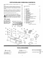
UNPACKING AND CHECKING CONTENTS
Model 149236222
carton,
Jolnter-Planer
is shipped
complete
TABLE OF LOOSE PARTS
tn one
Ul,
D:
Z,
E:
ITEM DESCRIPTION
b:
NO,
If any parts are missing,
do not attempt
to assemble
the
jointer-planer,
plug in the power cord or turn the switch on
O:
m:
LU:
03.
D:
O:
A
B
C
D
until the missing
ua:
E
z:
F
-a:
o:
G
"H
Separate all parts from packing materials and check each one
with the illustration and the tist of loose parts to make certatn
all items are accounted
for, before discarding
any packing
material
parts are obtained
Wipe all parts thoroughly
and are installed correctly.
with a clean, dry etoth
Apply a coat of cleat automobile
.K
paste wax to the tables
WARNING:
FOR YOUR OWN SAFETY, NEVER CONNECT TO POWER SOURCE UNTIL ALL ASSEMBLY
STEPS ARE COMPLETE, AND YOU HAVE READ AND
UNDERSTAND
THE SAFETY AND OPERATIONAL
INSTRUCTIONS.
a:
(9:
Z:
BOLT FINDER
Use to identify
fastener
size Hold head of screw
against folded edge. tn:
s_de diameter
or s_zea
circle is for nut, outside
diameter is for screw
q!
-o
_:.
*p
2!
318'
5116" 1/?
÷t0
2"
"a
*R
"s
T
U
V
W
X
_8
\,
lilt
*L
M
N
QTY,
Jointer-Planer
.................................
Fence ..............................................
Fence Bracket .........................................
Fence Segment ............................
Tilt Indicator. ............................
Chip Deflector ;: ,; ....................
Table Height Knob ...................................
3f8" Lockwasher
.....................................
1t4"-20 x 3t4" Hex Cap Screw ..........................
1f4 Split Lockwasher
.......................
1t4 Fiat Washer ..........................
Fence Lock Knobs ............................
9132" ID x 17f32" OD x 1t8" Thick Washer ..........
#10..24 x 112 Machine Screw ........................
#10 Flat Washer ......................................
#8-32 x 112" Flat Head Machine Screw ...............
#8-32 Hex Nut ..............................
#8 Flat Washer ................................
Push Block ............................................
2-112" to 1..1f4" Vac Hose Adapter ....................
1
1
2
2
2
1
1
1
4
4
4
2
2
2
2
6
6
6
2
1
5t32" Hex Key (Allen Wrench)
. ................
Owner's Manual
......................................
Cutter Guard Assembly ......................
1
1
1
'J ,J
• Supplied
in loose parts bag
Ill ,,
4
1
TOOLS REQUIRED
, !, ! ,_, _, I, I , _ q:_,tt"
14mm or 9116" Wrench
10mm Wrench
8mm or 5116" Wrench
Medium Slotted Screwdriver
#2 Phillips
Screwdriver
Combination
Square
SAFETY RULES FOR JOINTER--PLANER
Safety is a combination
of operator common senso and alertness at all times when the Jointer--Planer
used. Study these rules and general safety rules before operating and retain them for future use.
1, WEAR EYE PROTECTION
2 NEVER MAKE JOINTiNG
1t8 iNCH -- PER PASS
OR PLANING
CUT DEEPER
9 ALWAYS
narrower
inches
THAN
- Use hold downfpush
blocks for jointing
material
than 3 inches, or planing material thinner
than 3
10 ALWAYS., Keep cutter
3 FEED WORKPIECE
4 KEEP FINGERS
fixtures
AGAINST
AWAY
ROTATION
FROM
REVOLVING
CUTTER --
11 NEVER- Use in an explosive
motor may ignite fumes
use
when necessary
12
to
perform
an abnormal
or lJttte
operation
without study and the use of adequate
/push blocks, jigs, fixtures, stops, etc
8 NEVER-
Attempt
OUTDOOR
EXTENSION
atmosphere
CORD
USE.
Normal
When
sparking
of
toot is used
outdoors, use only extension cords suitable for use outdoors
Outdoor approved cords are marked with the suffix W-A, for
example- SJTW,-A or SJOW-A
OPERATION
6 NEVER FORCE CUTTING ACTION Stalttng or partial stalling
of motor can cause major damage. Allow motor to reach full
speed before cutting,
- Attempt
sharp
OF CUTTER
5, NEVER PERFORM
JOINTING
OR PLANING
WITH CUTTER HEAD GUARD REMOVED
7. NEVER
is being
13. ALWAYS
use identical
14 This tool is intended
WARNING:
used
DO NOT
replacement
parts when servicing
for RESIDENTIAL
ALLOW
USE ONLY,
FAMILIARITY
(GAINED
FROM
FREQUENT USE OF YOUR JOfNTER--PLANER)
TO BECOME
COMMONPLACE
ALWAYS
REMEMBER
THAT A CARELESS
FRACTION OF A SECOND IS SUFFICIENT TO INFLICT SEVERE
hold down
INJURY,
to cut small pieces.
WARNING: DO NOT AT ANY TIME LET BRAKE FLUIDS, GASOLINE, PENETRATING
OILS, ETC
COME tN CONTACT WITH PLASTIC PARTS. THEY CONTAIN CHEMICALS THAT CAN DAMAGE
AND/OR DESTROY PLASTICS.
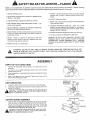
ASSEMBLY
DEPTH
OF CUT HAND
KNOB
1
Find one 3f8 tockwasher
parts bag.
2
Turn the nut on the height
extend beyond the nut.,
adjustment
screw
3
Place !ockwasher
onto screw
adjustment
screw and thread
4
Back nut up against hub of hand knob
wrench while hotdtng hand knob
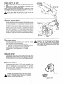
CHIP
and the depth
on height
of cut hand knob from
until
Tighten
five full
with
the
threads
hand knob
14mm or 9/16
3/8 HEX NUT
LOOSEN AND
RETIGHTEN
THiS SCREW \
DEFLECTOR
1
Loosen
2
Install slot of chip deflector
washer and retighten
,_
DEPTH OF CUT
HAND KNOB
the screw in the center
of vacuum
between
port of chip
the chip discharge
discharge,
and the fiat
CAUTION: THE CHIP DEFLECTOR MUST BE IN PLACE FOR SAFE
OPERATION.
FAILURE TO INSTALL THE CHIP DEFLECTOR
MAY
RESULT iN PERSONAL INJURY
CUTTER
GUARD
ASSEMBLY
1
Place the slot on the guard stop assembty over the tab on the front
cover as shown and a]ign the shoulder boff with the threaded hole
7
Rotate the cutter guard counterclockwise
until the tab is under the
cutter guard and tighten the shoulder bolt Be sure the cutter guard
rotates freely after tightening
the shoulder bolt
OPERATION,
FAILURE TO INSTALL THE CUTTER GUARD CAN
,_CAUTION:
THE CUTTER GUARD MUST BE tN PLACE FOR SAFE
RESULT IN SERIOUS PERSONAL INJURY
CH1P
DEFLECTOR
SHOULDER
SLOTS
BOLT
CCW
CUTTERGUARD
FENCE
1..
NOTE:USE
From among the loose parts find the following:
(1) Fence
(2) Fence Brackets
(2) Fence Segments
(2) Tilt Indicators
(2) Lock Knobs
(4) 114-20 x 3t4" Hex Cap Screws
(4) 1t4 Lock Washei's
(4) 9132 ID x 91t60D x 11t6 Thick Washers
MAY
(6)
Flat OD
Head
Machine
Screws
(2) #8-32
9f32 IDx !12
x 17132
x 1/8
Thick Washers
',o (6) #8 Fiat Washers
(2) #10-24 X 112 Pan Head Machine
(2)#10
and 114 lock washers,
1/_
THICK
LOCK KNO_
PROBLEM_;
_132
._
FE
HCESnAC_
_DX
_Tt3_OD
j_L._,jA.2_
,,A_2_AX_H_X
w
___'_1%_";
°°c"wAsH" __
......
#t0.z4x _/2 PAN,_0
3
PIEce assembled
fence segments
4
Position lock knobs with 9/32 tD x t7/32 OD x 118 thick washers
slots in fence segments and thread into fence brackets
5
Place squa_'e against face of fence and
square to table and tighten lock knobs.
6
THERE MUST BE 1/32" TO 1t16" gap between the lower edge of the
fence and jointer tables (with table set for 0" cut). To adjust, move
fence assembly by loosening the 1t4-20 x 314 hex cap screws attaching the fence brackets to the base Retighten hex cap screws after
adjustment
has been made
7
8
Recheck
fence
of
on machine
with
fence brackets
table surface
#8 flat
_"_
I
thru
Bring fence
fence,,
_
Install tilt indicators with #t0-24 x 112 pan head machine screw and
#10 flat washers_ Set 0 ° of indicators to 0 ° of segments
and tighten
thescrew
The fence should now be adjusted
_CH=NESCREW
inside the
r_
FENCE
THAN
snug but do not
Attach fence segments
to fence with #8-32 flat head screws,
washers and #8-32 hex nuts.
9,,
LEES
Tt(]HTEN_ND
\,._
2.
squareness
FENCE
Screws
1
washers
WASHER_
|t_
EASE.
FEat Washers
9132 ID x 1/16 thick
tighten
OF
RE/;DLT
and wilt accurately
measure
angles
t_ll
/
LU_=_,.--"_,_.}_'_,_
TILT
THE
INDICATOR
FENCE
_- _._ _*'J_l,_
"_-_.. _-_.._
2r"
.'="_/"
SHOULD
SEGMENT
AT
-"
_'___
'"-
w
C
Use #8 flat head wood screws of sufficient length to securely attach the
extension to the fence Make sure that the head of the screws are below
the surface of the fence so a s not to interfere with the workpiece
holes
may be drilled
1/4
in the
#,8 FLATHEAD
COUNT_
LINED
SCREW_
FENCE-t
-
'
UP WITH
O'MARK
TIGHTEN
To aid in edge jointtng of workpteces 4" and wider, you may extend the
fence height. The extension
can be constructed of 1" (314" thick) stock
pine or hardwood..
countersunk
THE
DO NOT OVER
EXTENSION
For extra stability,
additional
fence for flat head screws.
DE
A=
11116 Thick x 2" Wide x 10" Long
The 11116 thickness
can be obtained
on the jointer-plane[
by planing the board
B=
t12" to 3/4" Thick x 3-1t2" Wide x 10" Long
This piece may also be made out of plywood.
C=
3t4" Thick x 2-112" Wide x 19-112" Long
The 2-1/2" width may be Increased if desired
C
CHECKING
_
CUTTER
BLADES
CAUTfON:
MAKE SURE THE SWITCH IS IN THE OFF POSITION
AND CORD IS UNPLUGGED BEFORE PROCEEDING WITH CHECKING GUTTER BLADES
BLADE
WOOD
CUTTER
HEAD
CLAMP
The blades in your dointer-Planer
have been adjusted
at the factory to
assure proper operation
Shipping
and handling,
however,
may cause
misalignment
For accurate cutting,
the blades must be .003.in. higher
than the outfeed table (thickness of a piece of paper) when positioned
at
the highest point.
1
Block the cutter guard open with a scrap piece of wood about 4-112"
long between the fence and cutter guard
CHIP
Locate the slot in the cutter head shaft through the small hole In the
backside of the machine dt[ectly above the vacuum port. Rotate the
cutter head with a screwdriver
until one of the blades is at its highest
position.
Place a straight
edge over the outfeed
table and the blade The
straight edge must touch evenly on the outfeed table at both ends of
the blade Rotate the cutterhead
slowly, and making sure the blade
lightly touches the straight edge. If the straight edge rises or blades
do not touch, follow the "REPLACING
CUTTER BLADES" p_'ocedure
in the "MAINTENANCE"
section.
BACK SIDE
MACHINE
DISCHARGE/VACUUM
OF
STRAIGHT-
L
L_0UTFEED
TABLE
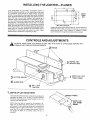
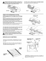
iNSTALLiNG THE JOINTER==-PLANER
]f the Jointer-Ptaner
is to be used in a permanent location, tt
should be fastened securely to a firm supporting
surface such
as a workbench_ Holes should be drilled through
supporting
surface of the workbench as illustrated
Each foot of the JotnterPlaner should be bolted securely
botts, 5f16" hex nuts, and look
!-I
-#---I_
using 5/!6" diameter machine
washers,
Bolts should be of
Jolnter.Planer
board securely
to board using hole pattern as shown
to workbench or supporting
surface,.
Clamp
KNOB
[
sufficient tength to accommodate
foot of Jointer-Raner,
washer,
hex nuts, and thickness of supporting
surface, Tighten all four
bolts securely_ tf the Jointer-P]aner
is to be used in a portable
application,
it is recommended that it be fastened-tea
mounting
board The board should be of sufficient
size to avoid tipping of
Jointer-Ptaner
while tn use Any good grade of plywood ot chipboard with a 3/4" minimum
thickness
is recommended
Mount
,..-_
SIDE
Supporting
WITH
surface
SWITCH/_
.......
where Jolnter-Planer
ts mounted
should
CONTROLS AND ADJUSTMENTS
,_
CAUTION: MAKE SURE THE SWITCH tS OFF AND THE CORD IS UNPLUGGED
FORMING ANY CHECKS OR ADJUSTMENTS,
BEFORE PER-
FENCE TILT
INDICATORS
3 CUTTER
4
4
!
GUARD
DEPTH OF CUT
HAND KNOB
GUARD STOP
ON - OFF
SWITCH
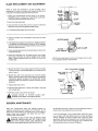
1.
DEPTH OF CUT HAND
KNOB
Turning the hand knob clockwise raises the infeed table and
decreases
the depth of cut Turning it counter-clockwise
lowers the infeed table and increases the depth of out to the
maximum 118" depth per pass
NOTE: When
the
table
is lowered
for the maximum
1t8"
depth cut, the hand knob will be relieved of lension and
will be loose If this is disturbing,
simply turn the hand knob
clockwise
until tt is again under tension Turn the knob no
more than 112 turn after it is again under tension
This will
not change the depth of cut setting
unless
!I2 turn is
exceeded
be
examined
carefully after mounting to insure that no movement
during use can result, tf any "tipping"
or "walking"
is noted,
secure workbench or supporting
surface before operating
NFEED
TABLE
H OF
CUT HAND
KNOB
CHECK
DEPTH
OF CUT
a
Place a straight
table.
edge on the outfeed
table extending
b.
Measure from the surface of the infeed table to the bottom
straight edge This will be the depth of cut.
OUTFEED
TABLE
over the tnfeed
MAX. DEPTH
OF CUT 1/8"
of the
NOTE: This Jointer-Ptaner
will make a maximum 118" deep cut. To reduce
THE DANGER of kickback and possible injury, the depth of cut should not
exceed 1f16" when cutting wood wider than 1-1/2"
CAUTtON:
MAKE SURE THE SWITCH IS OFF AND THE CORD IS
NPLUGGED BEFORE PERFORMING
THIS CHECK
2. FENCE
ADJUSTMENT
The fence can be adjusted to cut angIes from 0 ° to 45Q. The fence can
be tilted inboard (toward the cutter head) to maintain greater stability
of a narrow workpiece
or 45" outboard (away from cutter head) for
larger angle cutting operations
453 INBOARD
/
TO ADJUST: Loosen fence lock knobs and move the fence to desired
position. The angle setting ts marked on both fence segment pteces.
Set the ({3°) arrow of the ciear plastic tilt indicator
on the segment
marks for 5 ° Increments.
For 1 _ increments,
set the fence segment
mark between the 0 ° to 5" marks on the titt indicators
For outboard
tilt, add the reading on the tilt indicator to the reading on the segment
For inboard tilt, subtract the flit indicator reading from the reading on
the segment Tighten the lock knobs to maintain the desired setting
'\
TILT
iNDiCATOR
3. CUTTER
GUARD
_Ak
The cutter guard provides protection over the cutter
always be in place and functioning
properly
Check
a
the guard to make sure it is functioning
head. it must
properly
Pass a tf4" thick piece of wood over the cutter head between
guard and fence The guard must return automatically
the
CAUTION:
iF THE CUllER
GUARD FALLS TO OPERATE
PROPERLY,
CUTTER CONTACT
GUARD RETURN
SPRING
WILL
NEED THE
REPLACING.
YOUR NEAREST
SEARS STORE OR SERVICE CENTER FOR REPLACEMENT SPRING AND INSTRUCTIONS
BEFORE USING
THE JOINTER-PLANER.
Open the cutter guard ali the way until it stops and release
it several times it should always t"eturn to its orlg]na_
position
4. GUARD STOP
The Craftsman
JointedPlaner
comes equipped with a cutter guard
stop assembly to improve safety and reduce risk of injury. Be sure to
read and understand
all instructions
in the ASSEMBLY and BASIC
JOINTERIPLANER
OPERATION
sections before operating
this tool
5. ON-OFF
SWITCH
The operating positions of the "On-Off"
switch are located on the
front of your Jointer-Planer.
Push the switch up to turn your JolnterPlaner "on" and down to turn your Jolnter--Planel
"off". The switch
has a switch key which, when removed, allows the switch to be locked in the "off" position
To activate the locking feature push switch
to "off" posttlon and pull switch key.
\
WARNING:
BE SURE SWITCH
iS iN THE
"OFF"
POS]T1ON
_SWITCH
t_lL BEFORE PLUGGING JOINTER-pLANER
INTO POWER SOURCE
FAILURE
TO DO SO COULD
RESULT _N ACCtDENTAL
STARTING CAUSING SERIOUS iNJURY
SWITCH KEY
9
BASIC JOINTER=-PLANER
OPERATION
For your safety do not exceed a 1t16" deep cut on a planing
operation for work pieces wider than 1..1/2" For work pieces less
than 1-1t2", a 118" cut can be taken at a stow feed rate
For your own safety, ALWAYS use hold downtpush blocks when
JOINTING
wood that is NARROWER
than 3 in.. or when
PLANING wood that is THINNER than 3 in.
This Jo}nter-PJaner
is designed with a special cutter head and
internat baffle that blows the sawdust and chips from the rear of
the machine
To keep this system operating
properly, the motor
speed should be maintained.
A feed rate that is too fast will slow
the motor down resulting
in a poor cut and poor chfp discharge.
The type of wood, wood grain, and moisture content of the wood
all affect an acceptable
feed rate
Do not plane, joint or bevet wood shorter than 12 in Matertai this
short is more difficult
to control while being cuL Small pieces of
wood can tip over on the tables or into the cutterhead
and can be
kicked back toward you
For best resutts, take light cuts For average planing, jointtng, or
beveling, a cut between 1132 and 1t16 in. deep wil! produce the
best resutts
....
,_CAUTtON:
MAKE
SURE ALL SiX BLADE
LOCKING
SCREWS
ARE TIGHTENED
SECURELY
BEFORE ATTEMPTING TO TURN THE MACHINE'ON"
OR ATTEMPTING ANY OPERATION
SETTING
THE GUARD
STOP
3
Rotate the guard stop and knob clockwise until it contacts the
cutter guard and lock the knob To prevent binding or pinchlng,
some clearance will be required between the guard stop and
the cutter guard..
4
The guard stop is now set to cut workpiece
as the sample used in the set up..
5
Be sure to use this procedure
whenever
using the Jointerf
Planer and lock the cutter guard in the fuily closed position
when not in use to prevent Injury to anyone unfamiliar
with this
tooi_ Failure to do so may result in serious injury
CAUTION: MAKE SURE THE SWITCH iS IN THE OFF POSITION AND THE CORD UNPLUGGED BEFORE SETTING THE
GUARD STOP.
The guard stop assembly allows you to limit the cutter guard opening during operation and can be adjusted to prevent the cutter guard
from opening when the JolntedPtaner
is not in use.
As a Safety Cover
When the JointerlPlaner
is not in use, rotate the guard stop and
knob clockwise
until it contacts the cutter guard and lock the knob.
of the same width
During Operation
1.
With the Jointer/Planer
switch in the off position and the cord
unplugged
place a workpiece
of the size to be used on the
infeed table
2
Loosen the guard stop knob and pass the workplece between
the fence and the cutter guard and through the cutter area
until the cutter guard is rotated as far as this workplece wi!l
require
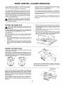
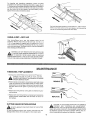
FEEDING
THE WORK
PIECE
Hoid the board firmty DOWN on both tables and AGAINST
keep fingers close together
the fence
Feed the board at a continuous
even rate of speed until the cut is
made along the entire length of the board Any hesitation
or stopping could cause a "step" to be cut on the edge of the board which
would cause the board to ride up on the outfeed table resulting in a
"crooked"
edge on the board
WI"Frl1HE GRA_
AGA|NST
WORK PIECE
THF_ GRA}N
_
FEED
Always feed WITH THE GRAIN whenever possible. If the nature of
the work ptece is such that it must be fed AGAINST THE GRAIN,
take very light c[Jts and feed siowiy.
ROTATION
HAND-OVER=HAND
Start with the left hand in the forward position. As the RIGHT hand
passes over the cutterhead,
remove the LEFT hand ,.CONTINUE
feeding while placing the LEFT hand behind the RIGHT Continue
feeding in this manner "hand over hand," until the entire length of
the board is cut Pressure should be applied over the cutterhead
and outfeed table
DO NOT FEED TOO FAST A slow steady rate of feed produces a
smooth accurate cut.. Feeding too fast causes a "rippled"
cut..
makes it difficult
to guide the workpiece
accurately
and could be
hazardous
10
,_WARNING:
NEVER PLACE THE HEEL OF YOUR HAND AT
THE END OF THE WORK PIECE WHEN FINISHING
A CUT.
THIS COULD RESULT tN YOUR HAND COMING IN CONTACT
WITH THE CUTTER CAUSING SERIOUS tNJURY.
At the end of the cut, position your hand on TOP NEAR THE END
of the work piece and continue
feeding the work piece until the
cutter guard has returned to its closed position
RIGHT
USING
HOLD
DOWNIPUSH
BLOCKS
ALWAYS use the hold down/push
blocks
that is NARROWER than 3 in or PLANING
than 3 in
when
wood
HAND'OVER
HAND
JO_NTING wood
that is THINNER
Grasp the hold downlpush
btocks firmly with the fingers close to..
gether and wrapped around the handle Position them fiat on top of
workpiece,
and push the workpiece down against the table to provide a quality cut and minimize the chance of a kickback.
Hold down pressure must be sufficient
to prevent hold down/push
block from sliding or slipping on the surface of the workpiece when
advancing work piece over cutter head
Use a handoover,.hand motion of the hold downlpush
blocks
careful to maintain control of the workpiece at all times
being
This means that once the work piece has passed the cutter head
onto outfeed table, one hold downlpush
block must always main °
tain contact with the work piece with outfeed table
When planing wood 3t4 in. thick and NARROWER than the hold
downlpush
btock, tilt the hold downlpush
block so that it clears
the top of the cutter guard while feeding.
Never plane wood that is thinner than 1/2 in .because
it is apt to
split or shatter and thus has a greater tendency
to kickback
,_CAUTION:
IF THE HOLD DOWNfPUSH BLOCKS TEND TO
SLIP WHILE FEEDING, CLEAN RUBBER SURFACE IMMEDIATELY WITH SANDPAPER.
BEVELING
AND
CHAMFERING
OUTBOARD
The fence on your jointer-planer
to 45 ° outboard
lock knobs
Adjust
is adjustable_rom
the fence to desired
45 ° inboard
angle and tighten
BEVELING is the cutting of an angle on the entire edge of a
board Beveling may require several passes due to the depth of
cut needed to bevel entire edge of board.
BEVEL
EDGE
CHAMFER
EDGE
CHAMFERING
is removing
only lhe corner of the edge of a
board Normally a chamfer is made with one cut; therefore, a cut
deeper than 1116" may be made
tl
Forbeveling
andchamfering
operations,
follow
the
same
procedure as for jointing and planing described on pages 10 and
1t Before performing
these operations make sure the surface of
the work piece that contacts
the fence is fiat and smooth
Maintain firm control of the work piece at all times
against fence surface and tabie surfaces,
holding
it firmly
Use hold downlpush
bfocks
for wood
under 3 in, wide
Position
them so you have contro_ of the work piece at ail times and so
they do not contact the guard or the cutter head
USING A WET--DRY
Your Jointer-Ptaner
Craftsman
Wet-Dry
VAC
has a rear chip exhaust
which fits all
Vacs with a 2-1/2 inch hose A 2-112 In, to
1-114 in, hose adapter is supplied
with the machine for 1-1/4 in,
hose connect}ons,
Attaching
a Craftsman
Wet-Dry Vac will keep
your work area cleaner, Craftsman Wet-Dry Vacs are available at
Sears Catalog and Retail Stores.
WARNING:
DO NOT REMOVE
CHIP
DEFLECTOR
EVEN
_F VACUUM HOSE REMAINS PERMANENTLY
ATTACHED TO MACHINE,
NEVER LEAVE HOSE ON MACHtNE
DURING OPERATION
iF A VAC IS NOT USED DURING OPERATtON OR THE HOSE AND MACHINE WiLL CLOG WITH CH_PS
CHiP EXHAUST =
VACUUM PORT
MAINTENANCE
TIMING
BELT REPLACEMENT
1 UnpJug your Jointer,.Planer
and put switch
in OFF position
PLANER
RESULT
IN ACCIDENTAL
STARTING
DANGER: COULD
FAILURE
TO UNPLUG
YOUR JO_NTER-CAUSING SERIOUS iNJURY
,_
2 Remove access covet plate by loosening
two pan head screws
under the machine and one located under the cutter guard,
being careful not to damage or disconnect
the switch wiring
DO NOT remove cutter guard or guard spring from access
cover,
3 Remove old timing
ward pressure
belt by turning
belt and maintaining
out-
4 Replace with new tfmlng belt by turning belt end maintaining
inward pressure NOTE: Make sure full width of bett is on
both pulleys,,
CUTTER
_[!
Oil and
GUARD
RETURN
O NOT LUBRICATE
GUARD
lubricating
products
damage andtor destroy
SPRING
CAUTION:
PROPERLY
(SEE "CONTROLS
AND ADJUSTMENTS '!
SECTION), THE CUTTER GUARD RETURN SPRING WILL
NEED REPLACING
CONTACT YOUR NEAREST SEARS STORE
OR SERVICE CENTER FOR REPLACEMENT
SPRING AND IN..
THE PIVOT POINT OF THE CUTTER
may contain
the cutter
chemicals
guard or other plastic
that
fF THE CUTTER GUARD FAILS TO OPERATE
can
parts
STRUCTIONS
12
BEFORE USING THE JOINTER--PLANER
BLADE REPLACEMENT
AND ADJUSTMENT
NOTE: To rotate the cutterhead
or to hold it steady, use a
screwdriver
in the slot in the cutter shaft through the small hole
in the rear of the machf_'le just above the vacuum port.
BLADE
3 Using
WOOD
BLOCK
CUTTER_
HEAD
1. Unplug your Jointer-Ptaner
and put switch in off position
DANGER: Failure to unplug your Jointer-Planer
could result
in accidental sta_:ting causing serious injury
2 Btock the cutter
t
CLAMP
guard open.
CUTTER
the 5132" hex key (A_len wrench),
btade lock screws
securing
blade and blade clamp.
4. Lift blade and blade clamp
5. Clean any sawdust
removed
from
remove the three (3)
from cutter head
cuttethead
and any parts you have
BLADE
6 Place blade clamp against the replacement blade and replace
in cutterhead with the (3) blade lock screws. NOTE: Retighten
bfade lock screws so that the blade is he_d by friction but still
a]lows for blade movement
CU'_ER
HEA_
BLADE _/_BLADE
7. Place a straight edge across the outfeed
cutterhead opening
8. Rotate
the cutterhead
table and across
unti_ the blade contacts
LOCK SCREW
the straight
edge (rotate backwards
to prevent damage to the cutting
edge). A properly adjusted
blade will lightly tick (touch) the
straight edge
9. BLADE TOO HIGH: If the straight
tt must be _owered
wood to lower it_
edge is lifted
NOTE: Check blade height aI both ends of blade. After
one is adjusted, repeat for second blade
by the blade,
CHIP
,_
DISCHARGE/VACUUM
BACK SIDE
MACHINE
I
STRA IGHTEDGE
/
blade lock screws.
12. Recheck blade adjustment,
with outfeed table
13. Recheck
the first
Tap the blade lightly with a scrap piece of
10 BLADE TOO LOW: If the blade does not touch the straight
edge, it should be raised Pry the lower edge of the blade with
a screwdriver
against the edge of the outfeed table Always
protect the edge of the table with a scrap of wood or piece of
cardboard
11. Tighten
CLAMP
the
screws
making
sure blade
is still
level
to be sure they are secure
iOUTFEEDTABLE
DANGER: COULD
FAILURE
TO IN
TtGHTEN
SCREWS
RESULT
SERIOUS BLADE
INJURY. LOCK
GENERAL MAINTENANCE
Keep
your
Jotnter-Planer
clean
and
adjusted
property
for
DO NOT allow anything to obstruct the chip discharge
disturb the air flow produced by the cutter head
maximum
performance
and longevity
of the rnachtne. Do not
allow pitch to accumulate
on the tables, fence, cutter guard, or
blades. Clean them frequently
with Sears Gum and Pitch
:_emover stock number 4919t.
outlet
or
lI the chip discharge
of your Jotnter*Planer
clogs with chips,
turn the switch OFF and UNPLUG the unit to avoid accidental
starting
D_atodge the chips and debris with apencit
or small
wood dowel. When resuming operation with the same work piece,
feed at a stower rate to avoid re-clogging
Use of a Wet-Dry Vac
will virtually eliminate the chances of clogging.
GASOLINE,
PENETRATING
OILS, ETC. COME'" IN CON,_WARNING:
DO NOT AT ANY TtME LET BRAKE FLUIDS,
TACT WITH PLASTIC PARTS THEY CONTAIN
CHEM..
tCALS THAT CAN DAMAGE AN DtOR DESTROY PLASTICS.
13
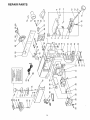
REPAIR PARTS
to
CO
LO
t4
e,i
e41
Z
,,,.J
d,
"0
ILl
Z
..3
=.
2_.
!--
--
Z
J
o
_.
I
Z
0
Z
_5
z
,..n
t;_
]"*.
z
t*t_
.
,5
e,_
co
Z
_
0
o
2
_S8
ii
0
'=":'
_z
_o
_p
<..._
_
=_-
_=_.
>.-...__'_=
i*=-
_n
.._
io
i .
_0
iz
oo@8
6_
_
oo
_2_ °°oo
_'&_'_
o_NN
i<
im o
i
15
99_8_8
,_e?SegeNN
o3
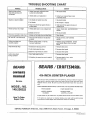
TROUBLE SHOOTING
TROUBLE
CHART
PROBABLECAUSE
Woodstrikes outfeed
table after passing over
cutterhead
Ripples on planed sU."i',face
Planedsurface not:straight
Blades impioperly adjusted betow
surface of outfeed table
REMEDY
! .............................................
Re-adjustblades
!
2 tnfeed table oul of adjustment
2 Contactyour nearest Searsstore
or service center'
1 Oneblade set higher than other
1 Re-adjustblades
2 Dull blades
2 Re-sharpenor replace
3 Board not held firmly against fence or
outfeed table
3 Holdboard firmly against fence and
outfeed table
1 Infeed fable looseorout of adjustment
1 Adjust infeed'tablei'see'Maintenance
section
2 Bladesset too low
2 Re-adjustblades
Excessivegougin_ at end of cut. ! Bladesset toohigh aboveoutfeed table
1 Resetblades
90 ° and 45 ° cuts inaccurate
t Fenceand tilt indicators not adjusted
propefly.
1 Re-adjustfence, seeAssembly
section.
Cutter guard does not
function properly
! l_,eturnspring b[oken, or spring
has beenweakened
I Replacespringimmediatety Contact
your nearest Sears store or service
center.
Chip discharge clogs
1 Obstruction'reducing air flow
i
2 Cutter head speed too stow
2 Decreasefeed speed
3 Woodhas high moisture content
3 Decreasefeed speed
1 Work feed speedtoo fasi
1 Decreasefeed speed
Cutter slows down
during operation
.....
2 Attempting to removetoomuch material
.........
Removeobstruction,
2_ Decreasedepth of cut, make
twoor morecuts
r"
i'
4VB-INCH JOINTER-PLANER
Now that you have purchased your JointeroPlaner,
should a need ever exist for
repair parts or service, simply contact any Sears Service Center and most Sears,
Roebuck and Co stores, Be sure to provide all pertinent facts when you call or
visit,
Service
MODEL;'NO.
149.236222
WHEN ORDERING
REPAIR PARTS, ALWAYS GIVE THE FOLLOWING
* PART NUMBER
• PART DESCRIPTION
" MODEL NUMBER:
149 236222
• NAME OF ITEM:
JOINTER--PLANER
INFORMATION:
Atl parts listed may be ordered from any Sears Service Center and most Sears stores
How To Order
Repair Parts
SEARS,
ROEBUCK
If the parts you need are not stocked
locally, your order will be electronically
transmitted
to a Sears Repair Parts Distribution
Center for handling
AND CO., Dept. 698/731A,
Sears Tower,
Chicago,
'r
IL 60684
P_inted in US,A