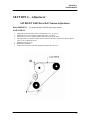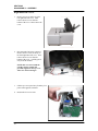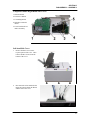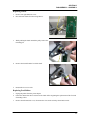
1
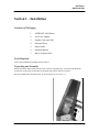
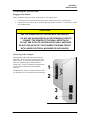
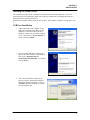
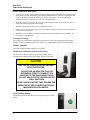
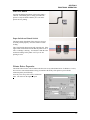
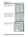
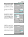
AstroJet 5000
PRINTER
SERVICE
MANUAL
ASTRO MACHINE CORP.
630 Lively Blvd.
Elk Grove Village, IL 60007
Phone: (847) 364-6363
Fax: (847) 364-9898
www.astromachine.com
SAFETY PRECAUTIONS
THIS EQUIPMENT PRESENTS NO PROBLEM WHEN USED PROPERLY.
HOWEVER, CERTAIN SAFETY RULES SHOULD BE OBSERVED WHEN
OPERATING THE ASTROJET 5000 PRINTER.
BEFORE USING THE PRINTER, YOU SHOULD READ THIS MANUAL
CAREFULLY AND FOLLOW THE RECOMMENDED PROCEDURES, SAFETY
WARNINGS, AND INSTRUCTIONS:
ü Keep hands, hair, and clothing clear of rollers and other moving parts.
ü Avoid touching moving parts or materials while the machine is in use. Before clearing a jam, be sure
machine mechanisms come to a stop.
ü Always turn off the machine before making adjustments, cleaning the machine, or performing any
maintenance covered in this manual.
ü A power cord is supplied with the machine. Plug it into a properly grounded wall outlet located near
the machine and easily accessible. Failure to properly ground the machine can result in sever personal
injury and/or fire.
ü The power cord and wall plug is the primary means of disconnecting the machine for the power
supply.
ü DO NOT use an adapter plug on the line cord or wall outlet.
ü DO NOT remove the ground pin from the line cord.
ü DO NOT route the power cord over sharp edges or trapped between furniture.
ü Avoid using wall outlets that are controlled by wall switches, or shared with other equipment.
ü Make sure there is no strain on the power cord caused by jamming between the equipment, walls or
furniture.
ü DO NOT remove covers. Covers enclose hazardous parts that should only be accessed by a qualified
service representative. Report any damage of covers to your service representative.
ü This machine requires periodic maintenance. Contact your authorized service representative for
required service schedules.
ü To prevent overheating, do not cover the vent openings.
ü Use this equipment only for its intended purpose.
In addition, follow any specific occupational safety and health standards for your workplace or area.
This manual is intended solely for the use and information of Astro Machine Corp., its designated agents,
customers, and their employees. The information in this guide was obtained from several different sources
that are deemed reliable by all industry standards. To the best of our knowledge, that information is
accurate in all respects. However, neither Astro Machine Corp. nor any of its agents or employees shall be
responsible for any inaccuracies contained herein.
AstroJet TM is a registered trademark of Astro Machine Corp.
Hewlett-Packard is a registered trademark of Hewlett-Packard Corporation.
Windows 98 and Windows XT are registered trademarks of Microsoft Corporation.
IBM is a registered trademark of International Business Machines.
All other trademarks are the property of their respective holders.
All rights reserved. No part of this book may be reproduced or transmitted in any form or by any means, electronic or mechanical,
including photocopying, recording, or any information storage and retrieval system, without permission in writing from the publisher
TABLE OF CONTENTS
Table of Contents
SECTION 1 – Installation
1
Contents of Packaging
Tools Requires
Unpacking and Assembly
Connecting the AstroJet 5000
Installing the Inkjet Cartridges
Installing the Printer Driver
1
1
1
3
4
5
SECTION 2 – Trouble Shooting
9
Power Problems
Interface Communication Problems
Feeding Problems
Software Problems
9
9
10
12
SECTION 3 – Functional Operation
13
Sequence of Operation
Printer Controls
Printer Driver Properties
13
14
15
SECTION 4 – Adjustments
21
Drive Belt Tension Adjustment
SECTION 5 – Disassembly and Assembly
Basic disassembly
Replacing Separator Tips
Service Disassembly Procedures
Right-hand Side Cover
Left-hand Side Cover
Replacing Motor Drive Belt
Replacing Feed Rollers
Replacing Main PC Board
Removing and Replacing Cleaning Station
Removing the Print Engine
Replacing Transport Rollers
SECTION 6 – Maintenance
The Inkjet Cartridge
Jams in the AstroJet 5000Printer
Replacing the Sheet Separators
Cleaning
Appendices
Appendix A – ASTROJET 5000 Specifications
Appendix B – Supplies and Optional Hardware
Appendix C – Wiring Diagram
21
23
23
23
23
24
25
26
27
30
31
33
36
39
39
40
41
41
43
43
44
45
i
TABLE OF CONTENTS
NOTES
ii
SECTION 1
INSTALLATION
Section 1 – Installation
Contents of Packaging
1.
ASTROJET 5000 Printer
2.
AC Power Adapter
3.
Parallel Cable and USB
4.
Software Driver
5.
Paper Guides
6.
Operator Manual
7.
Driver Software Disk
Tools Required
Tools required Standard #2 Phillips head screwdriver.
Unpacking and Assembly
Remove the Printer and its parts from the carton. Remove all packing tape. The screws that attach the
various parts of the guides to the printer are under the tape in their respective positions.
Begin by installing the Fixed Side Guide. It is held in place by two screws [1]:
1
SECTION 1
INSTALLATION
Next install the Adjustable Side guide using the two screws
[2] provided.
Attach the Rear Paper Support using the two knobs [3]
provided.
NOTE: the large slots fit over the socket head screws.
Install the Back Guide using the thumbscrew and washer
[4] provided. The washer goes between the screw and the
Rear Paper Support.
2
SECTION 1
INSTALLATION
Connecting the AstroJet 5000
Plugging in the Printer
Make sure that the main power switch of the Printer is in the OFF position.
1.
2.
Connect the power cord from the power pack to the connector [4] at the rear of the Printer.
Plug the power cord into the power pack and then plug the other end into a 115-220 Volt AC, 50/60
Hz. Grounded outlet.
CAUTION
USE THE POWER SUPPLY PACKED WITH THE PRINTER.
DO NOT USE AN ADAPTER PLUG OR EXTENSION CORD TO
CONNECT THE PRINTER TO THE WALL RECEPTACLE.
DO NOT USE OUTLETS CONTROLLED BY WALL SWITCHES.
DO NOT USE AN OUTLET THAT SHARES THE SAME CIRCUIT
WITH LARGE ELECTRICAL MACHINES OR APPLIANCES.
Connecting to the Computer
The Printer has both a USB and a Parallel Port [1]
connection. The two ports are located one above the
other as shown. If you use the parallel printer cable
from your computer plug it in and latch the two
locking clips. If using a USB Port [2] plug that cable
into the connector mounted below the parallel
connecter.
The Main Power Switch [3] should be turned on after
you attach the power cord to the Power Receptacle [4]
3
SECTION 1
INSTALLATION
Install the Inkjet Cartridges
The AstroJet 5000 uses two ink cartridges, the HP57 Color cartridge and the HP56 or HP58 Black
cartridge. Use the HP56 Black cartridge for everyday printing and the HP58 Black Cartridge for photos
and high quality printing.
Install and replacing the cartridge is done in the following manner:
4
1.
Plug in the Printer and turn the main
power switch ON. Open the top cover
and press the soft power button [1], the
button will light... The printhead
carriage will move side to side and the
printhead wiper mechanism will move to
its downward position. Wait until the
mechanism stops moving. Then open
the two printhead latching covers [2] by
lifting them from the front.
2.
Inset the cartridge in their appropriate
positions as shown. The color cartridge
goes on the left.
3.
Press down on the cartridge latches until
you hear a click, and then close the
machine cover.
SECTION 1
INSTALLATION
Installing the Printer Driver
The installation procedure for the AJ5000 driver is different for USB and Parallel Ports. Follow the
instructions below for installing the printer with a USB port. Instructions for installing the printer on a
Parallel Port follow the instructions below.
Install the disk supplied with the printer in your CD drive. If the Window’s Explorer window opens, close
it.
USB Port Installation
1.
Connect the printer to the computer via the
USB port and turn the printer ON. In a few
minutes the “Welcome to the Found New
Hardware wizard” will open on the computer
screen. Check the box “No, not this time” as
shown. Then click NEXT>.
2.
The next window that opens will show the
name of the printer AMC50 or AMCAMC50.
Click on the “Install the software
automatically (Recommended” box and then
click on NEXT>.
3.
After a few moments the window shown
below will appear, and then the “Hardware
Installation” window will appear. Click on
“Continue Anyway” and the driver software
will load from the disk.
5
SECTION 1
INSTALLATION
4.
Once the driver is loaded the
“Completing the found New Hardware
Wizard” window will appear. Click
FINISH.
5. The installation is complete when the “Found New Hardware” box appears in the lower right-hand
corner of your screen.
Parallel Port Installation
6
1.
Connect the printer to the computer via the Parallel
port (LPT1) and turn the printer ON. If the disk loads
and the “Welcome to the Found New Hardware
wizard” opens; CLOSE it.
2.
Click on START and then Printers and Faxes.
When the “Printers and Faxes” window opens click on
Add a printer.
3.
The “Welcome to the Add Printer Wizard”
window will open. Click NEXT.
SECTION 1
INSTALLATION
4.
Click on the Local printer attach to the
computer and Automatically detect and install
my Plug and Play printer buttons in the “Local
or Network Printer” window. Then click NEXT.
5.
The “Welcome to the Found New Hardware
Wizard” window will then open. Click on No,
not at this time and then click NEXT.
6.
In the “Found New Hardware Wizard” window
that appears next, click on Install the software
automatically (Recommended) button and
then click NEXT.
7.
The installer will look for the disk. This may take a
few minutes. Then the “Please wait while the wizard
installs the software…” will open as will the “Copying
Files” window.
7
SECTION 1
INSTALLATION
8.
After a few moments you will see the “Hardware
Installation” window. Click on the Continue
Anyway button to continue the installation of the
software.
9.
When the “Completing the Found New Hardware
Wizard” window opens click FINISH.
10. The “New Printer Detection” window opens. It is
a good idea to print a test page at this point to
confirm that the printer driver and the printer are
communicating. Load a sheet of 8-1/2” X 11”
paper in the printer and click NEXT.
11. Once the test page is printed the “Completing the
Add Printer Wizard” window will display
information about the printer. Click FINISH to
close the window.
12. Restart the computer to complete the installation.
8
SECTION 2
TROUBLE SHOOTING
Section 2 – Trouble Shooting
This section is arranged by first the condition that might occur, and then by possible
problems, their cause and recommended solutions.
Power Problems
CONDITION
PROBLEM
Power is on, nothing happens.
No power to printer
SOLUTION
Check that the power cord is plugged in.
Check that the power outlet is live.
Replace AC Adapter...
Interface Communication Problems
CONDITION
Printer does not respond to
software.
PROBLEM
Connection problems.
SOLUTION
Check that port is
communicating with printer by
using another parallel or USB
cable, replace cable.
Check cable connection to see if
any of the pins are bent or
missing. If so replace cable.
If port cannot communicate using
another parallel or USB cable,
check printer.
If port cannot communicate using
another parallel or USB cable
and the printer is OK, check
parallel or USB port on the
computer.
Printer not responding to
software
Poor connection between printer
and computer
Turn printer off and on again.
Check connections.
9
SECTION 2
TROUBLE SHOOTING
Feeding Problems
CONDITION
Intermittent feeding
Multiple feeds
PROBLEM
Feed ramp not used
The feed ramp adds a slope to the stack
and helps feeding.
Side guides set improperly
Loosen the side guides slightly.
Dirty feed rollers
Clean the feed roller with distilled water
and a cloth. DO NOT use any solvents or
detergents as they may damage the feed
rollers.
Paper stuck together
Fan media before placing it in printer
Uneven mail piece
Tap inserts to front of envelopes and retry.
Separator gap not set properly.
Adjust separators to thickness of media.
Media stuck together.
Fan the media before loading in printer.
Side guides too close to media
Push side guides away from media.
Brake misadjusted.
Failure to feed
10
SOLUTION
Adjust brake (see Section 4- Adjustments)
Side guides too close to media
Readjust side guides
No power to printer.
Check the power button is ON and that the
power cord is plugged in.
Feed gap too tight.
Adjust separator to thickness of media
Feed gap too loose
Adjust separator to thickness of media.
Material is out of specification.
Maximum thickness is 0.0625”
Motor on, feed rollers not turning.
Check for broken drive belt and replace,
Check for loose set screws on drive pulley
or belt drive roller pulley.
Clutch not engaging.
Replace Clutch.
Motor failure.
Check that motor is receiving power from
the power supply.
No power
See Power Problems in this Section.
SECTION 2
TROUBLE SHOOTING
CONDITION
Jams
PROBLEM
SOLUTION
Paper path obstruction
Clear jam and remove pieces remaining
under printhead.
Paper not loaded properly
Instruct operator in proper loading of
media.
Feed ramp not used properly
Set feed ramp
Separators improperly adjusted
Adjust separators to thickness of media.
Media curled or bent.
Uncurl media.
The separators are worn.
Replace separator tip.
Printing Problems
CONDITION
Extra lines; losing data
PROBLEM
Database problem
Improper output (address
information out of order, missfeeding, etc.)
Wrong interface settings
Static electricity
Media jams
Dirty media sensor
Double feeding
Media is curled or bent
Media is too thin
No communication
Improper cabling / connector
Unit not receiving power
Print too light or missing
character dots
Blurry address
Clogged or dirty printheads
Running out of ink
Image is not sharp
Split line of type
A line of type does not match
up.
Feeding problems
Paper Light Flashes
Double sheets.
Miss feeds.
Paper Miss Feed
Cancel Light Flashes
Ink Cartridge Missing
SOLUTION
Check data in database
program
Check software or data base
on PC.
Close the software and then
turn Printer of and on.
Clean media sensor.
Adjust Sheet Separators on
feeder.
Uncurl media.
The minimum thickness for
media is 0.006”.
Use Proper cable (see
Operator Manual).
Check plug connections,
on/off switch and fuse on
back.
Replace inkjet cartridges.
Replace the inkjet cartridge
or change the printer
resolution setting.
Check media thickness.
Check media thickness. The
minimum thickness for
material is 0.006”.
Increase the resolution of
the print.
Adjust the sheet separator.
Press the Paper button to
feed the paper into position
for printing.
Install print cartridge.
11
SECTION 2
TROUBLE SHOOTING
Software Problems
Refer to the manual for the application software being used.
12
SECTION 3
FUNCTIONAL OPERATION
Section 3 – Functional Operation
Sequence of Operation
The user prepares the printer
1.
Install cartridges in proper location.
2.
Uses a single piece of media to set sheet separators.
3.
Loads media and adjusts the side guide to within 1/32” of media.
4.
Stacks media in feeder and adjusts feed ramp.
5.
Turn printer on.
The user prepares the layout and creates a job
1.
The user selects the database and opens the layout software such as Microsoft Word.
2.
Creates a layout consisting of the variable data from the database using the merge function.
3.
User then creates a layout using fixed information such as return address and adds graphics as
required.
4.
User saves layouts.
5.
User initiates the Print function through the File menu in the program.
6.
User then selects through the printer driver properties menu paper size and desired print resolution.
7.
User then clicks on the print button to print the job.
Printing the Job.
1.
As soon as enough of the job is sent from the computer to the printer, the soft power button will begin
to blink. If this is the first job of the day, the printheads will automatically start the cleaning function.
Once this is complete the printer will begin to feed paper.
2.
After the media travels to the printer, the paper sensor will detect the lead edge of the paper and will
then stop the feeding and line up the lead edge of the paper with the printheads.
3.
The printheads then begin to move across the paper printing the job. After each pass the paper is
advanced by the paper feed clutch to continue the printing.
4.
When the first piece is printed it is ejected and the next piece is moved into position and aligned for
printing.
5.
When the last piece in the job is printed the printer ejects it and any pieces waiting to be printed.
6.
The printheads return to the capping station and remain there until the next job is sent.
Printing
The print engine consists of two printheads mounted on a movable shuttle. One printhead is three colors
(Cyan, Magenta and Yellow) and the other is Black to provide full color CMYK printing. The printing and
operation of the printer is controlled by the single main circuit board.
13
SECTION 3
FUNCTIONAL OPERATION
Printer Functional Description
1.
A photosensor located on the printhead carriage sees the lead edge of the paper, sends a signal to the
driver motor to reverse and align the paper with the printhead carriage, and sends a signal to the print
engine on the main board that the mailing piece is ready for printing. The feed clutch remains
disengaged as long as a mailing piece is in view of the photosensor.
2.
When the mailing piece uncovers the sensor the clutch engages the feed rollers and the next piece of
media starts moving toward the printer section.
3.
This cycle repeats itself as long as there is media in the feeder.
4.
Either the cycle stops when the feeder runs out of media, the operator stops the process, or there are no
records remain to be printed.
5.
When there are no records to be printed, the printer ejects any paper that is in line for printing. The
feed clutch is off at this point.
Cartridge Cleaning
The cartridges are cleaned at the beginning of each startup of a job by the cleaning station and at times
during a run that is determined by the printer software. A separate motor operates the cleaning station.
Printer Controls
The printer controls and their functions are as follows:
Main Power Connection and ON/OFF Switch
The AC Power Adapter provides the proper voltage to the printer.
The Main Power Switch powers up the printer when it is turned ON.
CAUTION
USE THE AC POWER ADAPTER PACKED
WITH THE PRINTER.
DO NOT USE AN ADAPTER PLUG OR
EXTENSION CORD TO CONNECT THE
ADAPTER TO THE WALL RECEPTACLE.
DO NOT USE OUTLETS CONTROLLED BY
WALL SWITCHES.
DO NOT USE AN OUTLET THAT SHARES THE
SAME CIRCUIT WITH LARGE ELECTRICAL
MACHINES OR APPLIANCES.
Clear Machine Button
This button operates the main drive motor to help clear paper from the
printer.
14
SECTION 3
FUNCTIONAL OPERATION
Soft Power Button
Pressing and holding this button will reset the printer’s
software. This button glows a steady green when the
printer is ready and blinks when the job is sent to the
printer and it is printing.
Paper Switch and Cancel Switch
The Paper Switch light blinks if the next piece does not
feed into position properly. Press the switch to resume
feeding.
The Cancel Switch when pressed will cancel the job. If the
light on this switch blinks it means that the printer is out of
ink or a cartridge is missing. You must have both the color
and black cartridge in the printer even if you are not
printing in color.
Printer Driver Properties
The Printer Driver for the AstroJet 5000 works the same as any other Printer Driver for Windows. It does,
however have some enhancements to help you maximize the ability of the printer to print variable
addressed quickly and efficiently.
Once the job is set up Click on File, and then on
Print. The widow on the right will open.
15
SECTION 3
FUNCTIONAL OPERATION
Paper/Quality Tab
If you then click on the Properties button, the
“Properties” window will open. Click on Size is box
to select the size of the material to be printed. You
can enter up to five custom sizes if the paper size you
are printing on is not listed.
The next step is to click on the Paper Length box to
select either Automatic Detection or Select from
above. Automatic Detection will cause the printer to
feed one sheet of paper and measure its length. The
printer will then use this information for each
succeeding sheet. The first sheet is not printed. Select
from above allows you to pick the paper size from the
Size is box and the first sheet will be printed.
The Type is box allows you to select the type of
paper you are going to print. Some settings such
as Photo Paper, Glossy will adjust the printing
mode in the software to account for the quality of
the paper.
16
SECTION 3
FUNCTIONAL OPERATION
Print Quality refers to the amount of ink and the
resolution of the image the printer will print. Fast
Draft uses the least amount of ink, has the lowest
resolution and prints the fastest. It is equivalent
to 300 dpi (dots per inch). Fast Normal and
Normal are approximately 600 dpi and print
slower, but at a higher quality. The Best setting is
approximately 1200 dpi and is used where high
quality images are required. Finally, there is the
Maximum DPI setting. This setting is used when
printing photos and has a correction routine
available under the Real Life Digital Photography
button to help improve the quality of photos you
print.
On this and subsequent pages in the Properties
window you will notice at the top the Print Task
Quick Sets menu. This menu contains some
standard setups for printing different types of
jobs. You may also add job setups to this menu
by typing in a description or name for a job and
clicking on the Save button. This is particularly
useful if you have some standard jobs you run all
the time. Highlighting the job and clicking the
Delete button will cancel any of the jobs in the
menu.
Finishing Tab
The Finishing tab give you the option of printing
more than one page on a single page or printing a
large single page over several sheets of paper to
make a sign or poster. To print more than one page
on a single page, click on the Pages per sheet menu
and select the number of pages you wish to print.
This option works with multiple page documents.
The default is one. The Poster printing option
works just the opposite way. If you wish to make a
document larger use this option to select the size of
the printed document. The default for this option is
OFF.
17
SECTION 3
FUNCTIONAL OPERATION
Effects Tab
The Effects tab gives you additional options for
print size. You can use the Print document on
option to specify a particular size of paper that you
want to print on regardless of the size of the original
document. The printer will reduce or enlarge the
output to match the document. If you select % of
normal size the printer will print the document in
the size you selected regardless of the size of the
paper. The Watermarks option prints a light
background watermark in the paper while printing
the original document. When this option is selected
the First page only option will let you print the
watermark on the first page, but not subsequent
pages.
The Edit button takes you to a second window that
allows customization of the watermark, including
font selection, color, density and you can also create you own watermark.
Basics Tab
The two important facts that you should be aware of
with the Basics tab window are the Orientation
should always be set to Portrait, never Landscape
and under Page order if you are printing a merged
data base, Front to back prints the last record first
and Back to front prints the first record first. The
Back to front is the fastest way to print database
records.
Copies, has a default of 1, buy you can select as
many copies per document as you require. The
Collate box will keep each set separate as it is
printed.
If you check the Show print preview box a
window will open before the printing starts so that
you can see the document as it will be printed.
This box has options to view the pages, start the
printing or cancel the job.
The Advanced features option on the right gives
you control over Ink volume which can be used to
put less ink on the paper to help drying on less
porous stock. The Dry time option will hold the
printout until the dry time has elapsed and then
print the next record.
The last option in this window is the Low
memory mode. Checking this box will manage
the memory in your computer to print a large job
if you do not have enough computer memory.
This box should be left unchecked unless you really need it.
18
SECTION 3
FUNCTIONAL OPERATION
Color Tab
The Color tab helps you control the printer’s color
output. If you wish to print in black only click on
the Print in grayscale and select one of the three
options that are available. The second option
Print in sepia will print a sepia colored color
image. You can not click on both the Print in
grayscale and the Print in sepia boxes together.
The default setting for Color space is
sRGB/sYCC. The other choices are AdobeRGB
and Managed by application. Unless you are
familiar with or have an application that can
manage the color use the default.
The Advanced color settings, gives you control of
the color and how it is printed. You can adjust
Saturation, Brightness and Color tone. You can
also adjust the individual colors with this window.
This is very useful when printing color photos.
The important thing to keep in mind when making changes to the standard settings in the driver is that if it
can not be done you will get an error message.
Service Tab
The service tab allows you to perform maintenance and check
functions on the printer.
19
SECTION 3
FUNCTIONAL OPERATION
Clicking on the Print a Test Page button will print a sample
page on the printer as shown.
Clicking on the Print a Diagnostic button will print the pattern
shown.
When the Clean the Print Cartridge button is pressed the “Clean the
Print Cartridge(s)” window appears and prints the page below.
Clicking on the Intermediate Clean button will present the screen
on the right. Clicking on the Prime button will take you to the next
level of cleaning if necessary. When the cartridges are clean click
20
SECTION 3
FUNCTIONAL OPERATION
on the Done button to exit this routine.
The Display Ink Level button will show you an
approximation of the amount of ink remaining in the
cartridges. This only works if you start with a new
cartridge and do not remove it during its use. Click
OK to exit this function.
The Calibrate the Device button is used to calibrate
the relationship between the black and color
cartridges to make
sure they line up
with each other.
This function is
usually performed
whenever a new ink
cartridge is installed
in the printer. Click
on Done when the
alignment is
completed or on
Align to repeat this
function. A copy of
the print that the calibration routine prints is shown here.
The Calibrate Color button has no function. Pressing it
will return the window on the right.
Tap 13
Tap 13 is a routine built into the printer to change the way it operates. When using tap 13, the printer will
print only the number of pieces chosen. It will not eject a blank piece at the end of the run. This eliminates
the last sheet being blank, but it does slow down the operation of the printer. Tap 13 feeds and prints one
sheet at a time. If you choose more than one sheet they will be printed, but each sheet is fed, printed and
ejected before the next sheet is fed.
To initiate the Tap 13 sequence press and hold the Soft key on the front of the printer, press the Cancel key
one time and then the Paper key three times. Then release the Soft key. The Cancel key light will blink
twice indicating that the Tap 13 sequence is initiated.
To print with this feature select the paper size you are printing on in the driver under properties and then
select the “Select from Above” option. If your paper size is not listed create a custom page size.
21
SECTION 3
FUNCTIONAL OPERATION
To cancel out of the Tap 13 sequence press and hold the Soft key on the front of the printer, press the
Cancel key one time and then the Paper key three times. Then release the Soft key. The Paper key light
will blink twice indicating that the Tap 13 sequence is off.
Turning off the printer will also cancel the Tap 13 mode of operation.
22
SECTION 4
ADJUSTMENTS
SECTION 4 – Adjustment
ASTROJET 5000 Drive Belt Tension Adjustment
REQUIREMENT:
To ensure the drive belt has the proper tension.
ADJUSTMENT:
1.
2.
3.
4.
5.
6.
7.
Unplug the machine and remove the Left-hand side cover. (6 screws)
Unplug the wires to the Switch PC Board and set the cover aside.
Loosen the two screws [1] that mount the main drive motor to the frame.
Move the motor up or down to obtain at between 0.085” and 0.065” deflection in the belt when a
force of 1 lb. is applied as shown.
Tighten the two screws [1].
Recheck the adjustment.
Connect the wires to the Switch PC Board and Replace the side cover.
23
SECTION 4
ADJUSTMENTS
Notes
24
SECTION 5
DISASSEMBLY – ASSEMBLY
Section 5 – Disassembly – Assembly Procedures
Basic Disassembly
Turn off Power
Disconnect Power Cord
Disconnect Interface Cable
Replacing the Separator Tips
1.
Before replacing the separator tips,
unplug the Printer.
2.
Loosen the separator locking knob and
raise the separator to its maximum up
position.
3.
Use a Phillips screwdriver and remove
the screw holding the metal cover over
the separator. Use the tip of the
screwdriver to pry the separator tip out
of its holder.
4.
Replace the separator tip, reinstall the
metal cover and screw. Do not over
tighten.
Service Disassembly Procedures
WARNING
THE FOLLOWING DISASSEMBLY SHOULD ONLY BE DONE BY A
QUALIFIED, TRAINED SERVICE REPRESENTATIVE.
CAUTION
ALWAYS WEAR A WRIST STRAP THAT IS GROUNDED WHEN
TOUCHING ELECTRONIC DEVICES.
25
SECTION 5
DISASSEMBLY – ASSEMBLY
Right-hand Side Covers
1.
Remove two screws at the top of the
rear right-hand side cover. Then
remove the two screws from the
bottom of the cover. Then remove the
cover.
2.
Disconnect the Fan Power connector.
Remove the two screws at the top of
the front right-hand side cover. Then
remove the two screws from the
bottom of the cover. Carefully pull it
away from the machine.
NOTE: this cover fits around the
cartridge storage station and
provides support for the top cover.
Take care when removing it.
3.
Lift the top cover up and away from the pivot
point on the opposite side frame.
4.
Reassemble in reverse order.
26
SECTION 5
DISASSEMBLY – ASSEMBLY
Components under Right-Hand Side Covers
1. Main PC Board
2. Pen Service Station
3. Forwarding Rollers
4. Main Power Inlet PC
Board
5. Feed Clutch and Feed
Roller Assembly
Left-hand Side Cover
1.
Remove the three screws at the
top non-operator side cover. Then
remove the three screws from the
bottom of the cover.
2.
Disconnect the wires attached to the
Paper and Cancel Switch PC Board
and the remove the cover.
27
SECTION 5
DISASSEMBLY – ASSEMBLY
Major Components under Left-Hand Side Cover
1. Clear Machine Switch
2. Drive Motor
3. Roller Drive Pulley
4. Drive Belt
5. Encoder Wheel
6. Encoder Sensor
Replacing Motor Drive Belt or Motor
1.
Remove left-hand side cover.
2.
Loosen the two motor mounting screws [1] to
relieve tension on the motor drive belt. The
remove the two screws [2] and the encoder
sensor.
NOTE: When removing the motor, disconnect
the wires and remove the two mounting
screws.
CAUTION
TAKE CARE WHEN REMOVING THE MOTOR DRIVE BELT THAT YOU DO NOT
SCRATCH OR OTHERWISE DAMAGE THE ENCODER WHEEL. THE BELT HAS
TO BE LIFTED OVER THIS WHEEL.
3.
Carefully remove the motor drive belt by
lifting it over and around the encoder wheel.
4.
Replace the belt in reverse order, and then
adjust the belt per the adjustment instructions
in Section 4.
28
SECTION 5
DISASSEMBLY – ASSEMBLY
Replacing Clutch
1.
Remove rear right-hand side cover.
2.
Disconnect the clutch from the wiring harness.
3.
While pushing the clutch toward the pulley remove the
mounting pin.
4.
Remove the clutch from the feed roller shaft.
5.
Reassemble in reverse order.
Replacing Feed Rollers
1.
Unplug the printer from the power adapter.
2.
Follow the instructions above and remove the clutch before beginning the replacement of the feed and
forwarding rollers.
3.
Remove the left-hand side cover, disconnect the wires on the switch pc board and set aside.
29
SECTION 5
DISASSEMBLY – ASSEMBLY
4.
Remove the side paper guides and the rear paper support.
5.
Put the Sheet Separators in the up position and remove
the two screws from each side of the separator guide
assembly and remove it from the machine.
6.
Remove the three screws on each side of the machine
that hold the Rear Deck in place
7.
Lift the Rear Deck from the machine and set aside.
8.
Remove the Feed Roller Drive belt.
30
SECTION 5
DISASSEMBLY – ASSEMBLY
9.
Remove the screw holding the Clutch Support Bracket
and remove the bracket.
10. Remove the Feed Roller Drive pulley.
11. Next remove the washer and spring from the Feed
Roller shaft.
NOTE: This spring and washer keep tension on the
clutch so that the pin holding the clutch remains in
place. Reassemble these parts in the order
removed.
12. Remove the two screws holding the Bearing Housing to
the side frame. Push the Roller assembly toward you to
release it from the bearing on the other side of the
machine and then lift the roller and shaft assembly from
the machine.
31
SECTION 5
DISASSEMBLY – ASSEMBLY
13. The two sets of forwarding rollers and shafts can be
removed in the same manner as the feed rollers and
shaft. Remove the bearing cap on the side frame,
slide the roller and shaft toward you and lift out of
the machine.
14. The rollers are attached to the shafts with Allen screws. Loosen the screws and slide the rollers off the
shafts.
15. Reassemble in reverse order, taking care that the belts that drive the rollers are reinstalled during
assembly.
Replacing Main PC Board
1.
Remove the two right hand side covers and the top cover.
2.
Unplug the PC Board power cord from the Power Inlet
PC Board.
3.
Unplug Connector [3], the two printhead ribbon cables
[2] and the cleaning station ribbon cable from the
Main PC Board.
CAUTION
THE RIBBON CABLES CAN BE
DAMAGED BY ROUGH HANDLING.
TAKE CARE WHEN REMOVING THEM
4.
Remove the two torque screws that attach the PC
Board to the support and remove the PC Board.
CAUTION
MAKE SURE THAT YOU ARE PROPERLY
GROUNDED WHEN HANDLING THE PC
BOARD. STATIC ELECTRICITY CAN
DAMAGE THIS BOARD.
32
SECTION 5
DISASSEMBLY – ASSEMBLY
5.
When replacing the Main PC Board make sure
that the Soft Power Button actuator is
positioned properly as shown in the photo. The
actuator goes around the switch on the PC
Board.
6.
Reassemble in reverse order.
Removing and Replacing Cleaning Station
1.
Remove the Main PC Board as in the steps above.
2.
Move the wire harness from the PC Board
mounting plate and then remove the PC Board
mounting plate by removing the two screws
shown. One is in the front and the other is on
the top of the print engine.
3.
Remove the PC Board mounting bracket
support bracket by removing the two screws.
33
SECTION 5
DISASSEMBLY – ASSEMBLY
4.
Remove the screw that attaches the Cleaning
Station to the Print Engine.
5.
Then remove the screw that attaches the
Cleaning Station to the Side Frame.
6.
Lift and pull the Cleaning Station away from
the machine.
7.
Reassemble in reverse order.
Removing the Paper Length Sensor
In order to remove the paper length sensor you must first remove
the Main PC Board and the Cleaning Station. Once this is
accomplished, the Sensor can be found on the side frame and held
in place by two screws. Unplug the Sensor’s connector and
remove the two screws.
Remove the sensor from the frame.
Reassemble in reverse order.
34
SECTION 5
DISASSEMBLY – ASSEMBLY
Removing the Print Engine
1.
See the instruction above and remove the side covers and the top cover.
2.
Then, remove the Main PC Board and Cleaning Station.
3.
Remove the four screws holding the cover over the print engine.
4.
Remove the guide plate by pressing down on the plate to free it from the guide plate shaft. Then, slide
it toward the feed end of the machine and remove it.
5.
Lift the spring from the guide plate shaft on the
right-hand side of the machine.
6.
On the left-hand side of the shaft is a second
spring. Lift it and remove the shaft from the
machine.
7.
Release the wiring harness from the clamp [2],
unplug the two top wires on the clear machine
switch [1] and unplug the connector on the
motor [3].
35
SECTION 5
DISASSEMBLY – ASSEMBLY
8.
Unplug the connector on the encoder sensor
assembly [4].
9.
Release the printhead encoder from the righthand side by pulling the end in the direction
of the arrow and slip it over the notch, then
releasing it from the left-hand side.
CAUTION
DO NOT REMOVE THE ENCODER
FROM THE PRINT ENGINE
ASSEMBLY.
10. Remove the frame mounting screw for the
printhead carriage shaft. There is a spacer
washer on the inside of the side frame
between the shaft and the frame.
36
SECTION 5
DISASSEMBLY – ASSEMBLY
11. Remove the torque screw on the other end of
the printhead carriage shaft.
NOTE: Do not remove the shaft from the
print engine assembly. When the screw is
removed the support/nut can be removed
from the frame. Set it aside.
12. Now remove the two screws on than attach
the print engine to the frame on the left-hand
side and the one screw that attaches the print
engine to the right-hand frame.
13. Grasp the print engine as shown and lift it
from the frame.
14. Reassemble in reverse order. Make sure that when installing the print engine the flat spring for the
center guide plate rod is pointed toward the rear of the printer.
DO NOT FORGET TO INSTALL THE SPACER
BETWEEN THE LEFT-HAND SIDE FRAME AND
THE PRINTHEAD CARRIAGE SHAFT.
37
SECTION 5
DISASSEMBLY – ASSEMBLY
Replacing Transport Rollers
1.
To replace the transport rollers first remove the covers, main pc board, cleaning station, and print
engine.
NOTE: This is to prevent damage to these parts and to give access to the transport rollers.
2.
Remove the front cover by removing the two
screws in the front cover and one screw on each
side of the front cover on the side frames. Then
lift the cover from the machine.
3.
To replace the exit transport roller remove the
bearing housing on the right hand side of the
machine and pull the roller toward that side and
lift out past the roller drive belt.
4.
Removing the transport roller requires removal of the main drive belt, the encoder sensor and the
encoder.
5.
Remove the encoder sensor pc board [2 screws]
and the encoder wheel [1 screw].
CAUTION
TAKE CARE WHEN REMOVING
ENCODER WHEEL. IT HAS TO BE
PULLED FROM THE SHAFT. MAKE
SURE IT IS NOT DAMAGED IN THE
PROCESS.
38
SECTION 5
DISASSEMBLY – ASSEMBLY
6.
Then remove Allen screw and the pulley from
the roller shaft and the bearing on the righthand side.
7.
Remove the roller.
8.
Removing the forwarding roller requires
removal of the pulley on the left-hand side of
the machine. Remove the bearing on the righthand side of the machine and remove the roller.
9.
Replace the rollers in reverse order. Make sure that the drive belts are in place when reassembling.
39
SECTION 5
DISASSEMBLY – ASSEMBLY
Notes
40
SECTION 6
MAINTENANCE
Section 6 - Maintenance
This section covers how to care for the ink cartridges, clear paper jams, replace the sheet separators, and
perform routing maintenance on the printer.
The Inkjet Cartridge
The AstroJet 5000 inkjet cartridges must be replaced when out of ink, when print quality is poor, or when
the built in cleaning has not helped the image quality.
The Approximate life of the Black number 56 inkjet cartridges based on three lines of 20 characters at 10point size per address is 20,000 addresses in the Fast Draft mode.
NOTE: These figures can vary depending on the font selected.
To Replace the Inkjet Cartridge:
•
Turn the printer on, open the top cover and press the soft key. Wait until the cartridge heads stop
moving then the latch lever to release the cartridge and pull the cartridge toward you and lift it
away from the holder.
•
Remove the new inkjet cartridge from its packaging, taking care not to touch the copper contacts,
the metal plate, or the gold printhead. Remove the protective tape from the printhead.
•
Slide the new cartridge into its holder and latch the locking lever.
•
Do not force the lever into place.
CAUTION
NEVER SHAKE, DROP, OR HIT THE CARTRIDGE AGAINST THE PALM OF YOUR
HAND OR ANY OTHER HARD SURFACE. SHAKING THE PRINT CARTRIDGE DOES
NOT “MIX” THE INK AND HITTING THE CARTRIDGE AGAINST A HARD SURFACE
DOES NOT CLEAR THE NOZZLES BOTH OF THESE ACTIONS ACTUALLY HURT THE
PRINT QUALITY BECAUSE THEY ALLOW BUBBLES TO FORM NEAR THE INK FIRING
CHAMBERS. THESE BUBBLES PREVENT THE NOZZLES FROM FIRING CAUSING
WHITE STREAKS IN THE PRINT IMAGE.
Storage
New cartridges should be stored in their original packaging and kept away from heat.
The cartridge once opened should remain in the printer.
Disposal
The cartridge may be disposed of in a normal manner.
If there should be an ink spill, use soap and water to clean up any problem areas. Abrasive soap works
well to get the ink off hands.
41
SECTION 6
MAINTENANCE
Cleaning the Printhead
The printheads in the AstroJet 5000 printer are cleaned automatically each time the machine is turned on or
when the printer software decides they need cleaning. No operator intervention is required.
Jams in the AstroJet 5000 Printer
If a jam occurs, STOP the Printer. You can do this by lifting up the front cover.
Some possible reasons for jamming are:
1.
Feeding more than one piece of media.
2.
Damaged media, such a dog-eared (turn down corners).
3.
Media that is not stiff enough may not be usable. Media that meets Postal stiffness requirements
for automated feeding is acceptable in the AstroJet 5000.
4.
Envelopes that are caught under the flap of another envelope or stuck to one another may cause
jamming.
Failure to Feed Paper Stoppages
If a sheet feeds, but does not get into the proper position to feed, you can clear it from the machine by
pressing the Green “Clear Machine Button”. This switch will operate the drive motor and rollers, but not
feed any additional paper.
Removing Jammed Media
It may be necessary to remove one or more of the
paper guides to gain access to the jammed media.
The forwarding roller guide plate can be removed
by pressing down on the plate and sliding it toward
the feeder end of the printer. Lift the plate out of
the machine.
NOTE: it is important that when this guide is
removed and reinstalled it does not have any side
to side play. If after installing the guide you can
move it from side to side, remove it and reinstall
it.
The front media guide can be removed by opening
the front cover, lifting the guide vertical and then
lifting it out of its guide on the printhead side of the
machine.
42
SECTION 6
MAINTENANCE
Misfeeds
Misfeeds cause the printer to stop and the Red light in the Paper Feed switch will blink. Press this switch
to restart the printer and feed the sheet. If the sheets continue to fail to feed, readjust the sheet separators to
the media or replace them.
Replacing the Sheet Separators
The sheet separators insure separation of the pieces as they are being fed. The do wear and must be
replaced from time to time. If you experience double sheet feeding and can not adjust the separators to
prevent it, they should be replaced. Replacement of the sheet separators is not difficult. Just follow the
steps below:
1. Turn off the AstroJet 5000 and unplug it from the power source.
2. Release the separator-by loosening knob [A]
and move the paper side guides to their
maximum open position.
3. Lower the separators so that they touch the
feed roller.
4. Remove the screw [B] and the separator
support [C.] Then remove the separator [D]
by prying it out of the holder.
5. Install a new separator in place and replace the
separator support and screw.
Cleaning
The AstroJet 5000
WARNING
THE PRINTER IS A PRECISION MACHINE THAT SHOULD BE CLEANED
REGULARLY TO INSURE MANY YEARS OF SERVICE. BEFORE PERFORMING
ANY MAINTENANCE DISCONNECT THE MACHINE FROM ITS POWER SOURCE!
The Printer must be cleaned regularly of accumulated paper dust and ink. Depending on the types of media
that are run, paper dust may accumulate within the printer and on the transport. Unplug the printer from the
power receptacle and remove the covers.
The internal areas are best cleaned with a vacuum that has a soft brush attachment to help loosen the dust
particles. Take care not to damage the PC Boards or electrical wiring.
The exterior of the machine may be cleaned with any standard household cleaner which is non-abrasive and
does not contain plastic harming solvents.
CAUTION
NEVER SPRAY OR POUR CLEANERS DIRECTLY ON OR INTO THE PRINTER.
EXCESS LIQUID COULD HARM ELECTRONIC PARTS. ALWAYS DAMPEN A RAG
WITH THE CLEANER AND APPLY IT TO THE PARTS TO BE CLEANED.
43
SECTION 6
MAINTENANCE
Feed Rollers and Forwarding Rollers
The feed and forwarding rollers can become glazed with paper lint and ink from the media. They should be
regularly cleaned with a mild abrasive household cleaner on a damp cloth.
Avoid using solvents on the rubber rollers.
44
APPENDIX
Appendix A – AstroJet 5000 Specifications
PRINT TECHNOLOGY
ADDRESS SPEED
PRINT QUALITY
(Dots Per Inch)
IMAGE AREA
PRINT ORIENTATION
FONTS
GRAPHICS, LOGOS, AND
BARCODES
MATERIAL SIZE
MATERIAL THICKNESS
FEEDER CAPACITY
PRINT COLORS
INK
SOFTWARE
FIRMWARE UPDATE
PC INTERFACE
DIMENSIONS
WEIGHT
ELECTRICAL
OPTIONS
Inkjet, one HP 57 Color and one HP 56 or HP 58 Black cartridge
Up to 4,000 #10 envelopes per hour
High Quality
1200 dpi
Standard Quality
600 dpi
Draft Quality
300 dpi
8.5 inches X 16 inches (215.9 mm x 406.4 mm)
Portrait and Landscape
All TrueType fonts available on PC
Allows printing of graphics, logos, and barcodes
Minimum: 3” x 5” (76 mm x 127 mm)
Maximum: 11” x 17”(279.4 mm x 431.8 mm)
Minimum: 0.006” (0.2 mm)
Maximum: 0.0625” (1.5 mm)
Up to 300 #10 envelopes
HP 57 full color, HP 56 and 58 black only
Water based may require drying assistance for coated stock
WindowsTM Printer Drivers for WindowsTM 98, 2000, NT, ME, and
XP
Via PC interface in flash proms.
Parallel and USB (1.1)
19.5” W x 22” L x 17.125” H (49.5 cm W x 55.9 cm L x 43.5 cm H)
40 lbs. (18.2 kg.)
115VAC or 240VAC 50/60 Hz
HP Versatile fast dry Black, and Red, Blue, Green, or Yellow,
Conveyor/Stacker, Drop Tray
All specifications are subject to change without notice.
45
APPENDIX
Appendix B – Supplies and Optional Hardware
The following supply items and optional hardware are available from your Astro
Machine Distributor:
Supplies
Black Inkjet Cartridge
HP 56
Photo Black Ink Cartridge
HP 58
Color Cartridge
HP 57
Optional Hardware
Conveyor /Stacker
Drop Tray
46
APPENDIX
Appendix C – Wiring Diagram
47
APPENDIX
NOTES
________________________________________________________________________________
________________________________________________________________________________
________________________________________________________________________________
________________________________________________________________________________
________________________________________________________________________________
________________________________________________________________________________
________________________________________________________________________________
48
Copyright © 2008 ASTRO MACHINE CORP.
Elk Grove Villa/e, IL 60007
04/24/2008
Part Number: 300-AJ5000 Rev. C