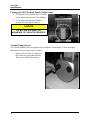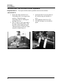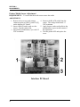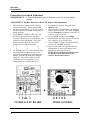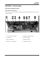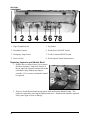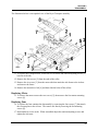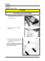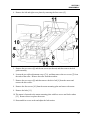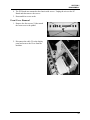
1
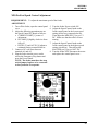
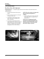
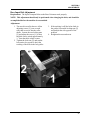
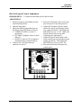
XPS-ProMail System XPS-ProMail Base, XPS-ProMail 3.0/4.0 print system, XPS-ProDry 8.0 Base, XPS-ProFeed Shuttle & TB-659 Conveyor SERVICE MANUAL Preliminary Revised: 8-10-07 Part #: M-? RENA SYSTEMS INC. 136 Green Tree Road STE 140 Oaks, PA 19456-1069 Phone: (610) 650-9170 Fax: (610) 650-9171 E-Mail: [email protected] Web Site: www.renausa.com 0 INDEX Table of Contents Section Page # DRYER SAFETY PRECAUTIONS ..........................................................................................................................4 GENERAL SAFETY PRECAUTIONS.....................................................................................................................5 SECTION 1 – SERVICE DIAGNOSTIC TESTS ....................................................................................................6 Loading a Test Print Image .............................................................................................................................................. 6 SECTION 2 – MAINTENANCE ..............................................................................................................................10 THE INKJET CARTRIDGE ...........................................................................................................................................10 Replacing the Inkjet Cartridge:..........................................................................................................................10 Storage ................................................................................................................................................................11 Disposal...............................................................................................................................................................11 Cleaning the Printhead (Inkjet Cartridge).........................................................................................................12 Purging the Nozzles ......................................................................................................................................................... 12 JAMS UNDER THE XPS-PROMAIL 3.0/4.0 PRINTER ...................................................................................................13 Removing Jammed Media ..................................................................................................................................13 CLEANING ................................................................................................................................................................14 Cleaning the Printer’s Media Thickness Adjustment Mechanism....................................................................14 Cleaning the Printer’s Media Sensors ...............................................................................................................15 Cleaning the Dryer & Dryer Lamps CAUTION!..............................................................................................15 Cleaning the XPS-ProFeed Shuttle Media Sensor ............................................................................................16 Vacuum Pump Service........................................................................................................................................16 SECTION 3 – TROUBLESHOOTING ...................................................................................................................19 POWER PROBLEMS ...................................................................................................................................................19 INTERFACE COMMUNICATION PROBLEMS ................................................................................................................19 LCD DISPLAY PROBLEMS ........................................................................................................................................20 FEEDING PROBLEMS .................................................................................................................................................20 PRINT PLACEMENT PROBLEMS .................................................................................................................................22 PRINT CONTENT INCORRECT ....................................................................................................................................23 SOFTWARE PROBLEMS .............................................................................................................................................23 PRINT QUALITY PROBLEMS ......................................................................................................................................24 SECTION 4 - ADJUSTMENTS...............................................................................................................................27 XPS-PROFEED SHUTTLE FEEDER ..........................................................................................................................27 XPS-PROFEED Drive Belt Adjustment ............................................................................................................27 XPS-PROFEED Top Feed Roller Parallel Adjustment ....................................................................................28 XPS-PROFEED SPEED CONTROL ADJUSTMENT ........................................................................................................29 XPS-PROMAIL BASE................................................................................................................................................29 XPS-PROMAIL BASE................................................................................................................................................30 Base Drive Motor Belt Adjustment.....................................................................................................................30 Base Input Belt Adjustment................................................................................................................................31 Base Vacuum Belt Adjustment...........................................................................................................................32 Base Unit Speed Control Adjustment.................................................................................................................33 DRYER BASE ............................................................................................................................................................34 Dryer Base Transport Belt Adjustment ..............................................................................................................34 Dryer Base Speed Control Adjustment...............................................................................................................35 TB-659 CONVEYOR ..................................................................................................................................................36 Conveyor Drive Belt Adjustment ........................................................................................................................36 Conveyor Transport Belt Adjustment.................................................................................................................37 1 INDEX Conveyor Speed Control Adjustment .................................................................................................................38 XPS-PROMAIL 3.0/4.0 PRINTER ...............................................................................................................................39 Printer Power Supply Output Voltage Adjustment ............................................................................................39 Printer Media Sensor Adjustment ......................................................................................................................40 Printer Speed Adjustment...................................................................................................................................40 Printer Speed Adjustment...................................................................................................................................41 Printer/Base Auto Speed Adjustment.................................................................................................................42 SECTION 5 – DISASSEMBLY...............................................................................................................................43 XPS-PROFEED SHUTTLE FEEDER .............................................................................................................................43 Control Panel Components ................................................................................................................................43 Replacing Separator and Shuttle Head..............................................................................................................44 Replacing the Forwarding Feed Rollers ............................................................................................................45 Replacing the Lower Feed Rollers .....................................................................................................................46 Removing Rear Covers .......................................................................................................................................46 Removing Rear Media Guide .............................................................................................................................46 Removing Side Media Guides.............................................................................................................................47 Removing the Top Plate......................................................................................................................................47 Removing the Drive Motor .................................................................................................................................49 Removing the Main Drive Belt ...........................................................................................................................49 Removing the Vacuum Pump.............................................................................................................................50 Removing the Vacuum Valve .............................................................................................................................50 BASE UNIT ...............................................................................................................................................................51 Electrical Component Location Base Chassis (top view) ..................................................................................51 Replacing Transport and Motor Drive Belts......................................................................................................52 Removing Vacuum Transport Belts ...................................................................................................................53 Transport Belt Removal......................................................................................................................................55 Removing and Replacing the Main Drive Belt. .................................................................................................56 DRYER BASE ............................................................................................................................................................57 Replacing Dryer Transport Belts........................................................................................................................57 Replacing Motor .................................................................................................................................................59 Replacing Fans ...................................................................................................................................................59 CONVEYOR ...............................................................................................................................................................60 Replacing Conveyor Belts...................................................................................................................................60 PRINTER ...................................................................................................................................................................62 Rear Cover Removal ...........................................................................................................................................62 Front Cover Removal..........................................................................................................................................63 APPENDIX A – SPECIFICATIONS .......................................................................................................................64 XPS-PROMAIL SYSTEM ...........................................................................................................................................64 XPS-PROFEED SHUTTLE FEEDER .............................................................................................................................64 XPS-PROMAIL 3.0/4.0 PRINTER ...............................................................................................................................65 APPENDIX B – SUPPLIES.....................................................................................................................................66 SUPPLIES ..................................................................................................................................................................66 2 DRYER SAFETY PRECAUTIONS THE FOLLOWING MUST BE READ AND UNDERSTOOD BEFORE OPERATING THE DRYER! DUE TO THE NATURE OF THE DRYER, IT PRESENTS UNIQUE HAZARDS AND RISKS THAT MUST BE UNDERSTOOD AND OBSERVED. DUE TO THESE HAZARDS, THE OPERATION AND USE OF THE DRYER REQUIRES SPECIAL ATTENTION. THE DRYER PRESENTS THE FOLLOWING HAZARDS: FIRE HAZARD: If media is left under the dryer lamps for more than a few seconds, it will ignite. SEVERE PERSONAL INJURY or DEATH HAZARD: If you touch the hot surface of the dryer or dryer base, a serious burn will result. Shock hazards are present, when not properly used/connected. The XPS-ProDry must be used correctly to prevent injury, death and or property damage. 9 Do NOT use the dryer unless you fully understand the risks associated with the dryer and you are willing to accept those risks. 9 Do NOT leave the dryer unattended. If a jam occurs under the dryer lamps, a fire can result within a few seconds. 9 A fire extinguisher (rated for energized electrical equipment and wood/paper/plastic/cloth fires) must be available and must be easily accessible at all times. 9 An inexperienced operator should NOT be allowed to use the dryer. Severe personal injury and or property damage could result. 9 Keep hands, hair, and clothing clear of dryer, dryer lamps, dryer rollers, belts and other moving parts. 9 Avoid touching moving parts or materials while the machine is in use. Before clearing a jam, be sure machine mechanisms come to a stop and dryer lamps are turned off. Press the Emergency Stop button. 9 Allow the dryer lamps to cool down for at least 5 minutes (lamps off, blowers on) before touching or cleaning the dryer or dryer lamps. 9 Always turn off the machine before making adjustments, cleaning the machine, or performing any maintenance covered in this manual. 9 The Dryer requires 240V and should be connected by a qualified electrician. It must be properly grounded. Failure to properly ground the dryer and dryer base can result in sever personal injury, death and/or fire. 9 The power cord and wall plug is the primary means of disconnecting the machine from the power supply. 9 DO NOT use an adapter plug on the line cord or wall outlet. 9 DO NOT route the power cord over sharp edges or trapped between furniture. 9 Avoid using wall outlets that are shared with other equipment. 9 Make sure there is no strain on the power cord caused by jamming between the equipment, walls or furniture. 9 DO NOT remove covers. Covers enclose hazardous parts that should only be accessed by a qualified service representative. Report any damage of covers to your service representative. 9 This machine requires periodic maintenance. Contact your authorized service representative for required service schedules. 9 To prevent overheating, do not cover the vent openings. 9 Use this equipment only for its intended purpose. 4 GENERAL SAFETY PRECAUTIONS CERTAIN SAFETY RULES MUST BE OBSERVED WHEN OPERATING THE XPS-PROMAIL SYSTEM. BEFORE USING OR SERVICING THE SYSTEM, YOU SHOULD READ THIS MANUAL CAREFULLY AND FOLLOW THE RECOMMENDED PROCEDURES, SAFETY WARNINGS, AND INSTRUCTIONS: 9 Keep hands, hair, and clothing clear of rollers and other moving parts. 9 Avoid touching moving parts or materials while the machine is in use. Before clearing a jam, be sure machine mechanisms come to a stop. 9 Always turn off the machine before making adjustments, cleaning the machine, or performing any maintenance covered in this manual. 9 Use the power cord supplied with the machine and plug it into a properly grounded wall outlet located near the machine and easily accessible. Failure to properly ground the machine can result in sever personal injury and/or fire. 9 The power cord and wall plug is the primary means of disconnecting the machine from the power supply. 9 DO NOT use an adapter plug on the line cord or wall outlet. 9 DO NOT remove the ground pin from the line cord. 9 DO NOT route the power cord over sharp edges or trapped between furniture. 9 Avoid using wall outlets that are controlled by wall switches, or shared with other equipment. 9 Make sure there is no strain on the power cord caused by jamming between the equipment, walls or furniture. 9 DO NOT remove covers. Covers enclose hazardous parts that should only be accessed by a qualified service representative. Report any damage of covers to your service representative. 9 This machine requires periodic maintenance. Contact your authorized service representative for required service schedules. 9 To prevent overheating, do not cover the vent openings. 9 Use this equipment only for its intended purpose. In addition, follow any specific occupational safety and health standards for your workplace or area. WARNING THERE ARE HIGH VOLTAGES PRESENT BEHIND THE COVERS OF THE XPS-ProMail SYSTEM! This manual is intended solely for the use and information of Rena Systems Inc., its designated agents, customers, and their employees. The information in this guide was obtained from several different sources that are deemed reliable by all industry standards. To the best of our knowledge, that information is accurate in all respects. However, neither Rena Systems Inc. nor any of its agents or employees shall be responsible for any inaccuracies contained herein. Hewlett-Packard is a registered trademark of Hewlett-Packard Corporation. Windows 98, Windows 2000, Windows ME, and Windows XP are registered trademarks of Microsoft Corporation. IBM is a registered trademark of International Business Machines. All other trademarks are the property of their respective holders. All rights reserved. No part of this book may be reproduced or transmitted in any form or by any means, electronic or mechanical, including photocopying, recording, or any information storage and retrieval system, without permission in writing from the Publisher. 5 SECTION 1 SERVICE DIAGNOSTIC TESTS SECTION 1 – Service Diagnostic Tests TEST PRINT key Pressing the TEST PRINT key momentarily will place the printer into the Test Printing mode. Press the ENTER key to print a test sheet. To access the Service Menu mode press and hold the TEST PRINT key until “Service Menu” is displayed on the printer control panel. Use the + or – key to step through the following test options: Loading a Test Print Image 1. Create the Test Print layout using any common application (MS Word, Flex Mail…). 2. Connect the printer and computer via parallel port or USB port. 3. Hold the Test Print key on printer control panel and turn the printer on. Release the key when message “Test Job to be saved – Preparing the flash area” appears. Message will change to “Test Job to be Saved – Waiting for job data” and Test Print light will come on. Printer is now ready for downloading. 4. Send “Print” one record to the printer. 5. Message will change to “Test job’s been Saved – Saving: xxxxxx “(size of file) NOTE: All printing parameters such a head alignments, feeder delay, speed, quality, language and orientation will be stored in flash memory together with file. Drive Speed Test Press the ENTER key to start the main drive motor and display the belt speed in inches per second. Press the ENTER key to stop the main drive motor. If the main drive motor does not start, the main drive motor circuitry has a problem. No reading in inches per second indicates an encoder problem. Motor Test Press the ENTER key to start the main drive motor. Press the ENTER key to stop the main drive motor. The main drive motor not starting indicates a problem in the main drive motor circuitry. Clutch Test Press the ENTER key to start the main drive motor and turn on the feed clutch. Press the ENTER key to turn off the feed clutch. If the clutch does not engage there is a problem with the clutch circuitry. Sensor Test Press the ENTER key to display the state of the paper sensor. Uncovered displays when the sensor is NOT covered. Covered displays when the sensor IS covered. Use a strip of paper inserted in the sensor area to test its function. Failure to switch between the tow messages indicates a problem in the sensor circuitry. Power Supply Test Press the ENTER key to display the voltage reading of the main power supply. The nominal reading is between 13.5 and 14.5 volts. The power supply may need adjusting to bring the value within the nominal range. 6 SECTION 1 SERVICE DIAGNOSTIC TESTS Encoder Test Press the ENTER key to display the current encoder count reading. Move the exit roller. If the number does not increase, this indicates an encoder failure. Keyboard Test Press the ENTER key to test the function of the individual keys on the keyboard. When a key is pressed the display shows the key name. To exit this test you must power the printer OFF. Head Lift Test The head lift test is not applicable to this system as the head adjustment is mechanical. Ink Levels The Ink Levels in each of the cartridges are displayed in this mode as a percentage. This will only display properly if the operator resets the system when a new cartridge is installed. 7 SECTION 1 SERVICE DIAGNOSTIC TESTS Notes 8 SECTION 2 MAINTENANCE SECTION 2 – Maintenance This section discusses how to care for the inkjet cartridges, clear paper jams, and perform routine maintenance to the XPS-ProMail System. The Inkjet Cartridge The inkjet cartridges must be replaced when out of ink, when print quality is poor, or when purging and cleaning have not helped the image quality. The Approximate life of the HP 51645A Inkjet cartridges based on three lines of 20 characters at 10-point size per address is: PCL Version: 600 X 600 DPI 300 X 600 DPI 200 X 600 DPI 150 X 600 DPI 50,000 addresses 100,000 addresses 150,000 addresses 200,000 addresses NOTE: These figures can vary depending on the font selected. The bulk ink cartridge will print approximately 10 times the number of address as a standard cartridge. Replacing the Inkjet Cartridge: 1. Remove the used cartridge from the cartridge holder by raising the latch lever to release the cartridge, and then pull the cartridge up and out of the holder. 2. Remove the new inkjet cartridge from its packaging, taking care not to touch the copper contacts, the metal plate, or the gold printhead. Remove the protective tape from the printhead. 3. With the cartridge’s printhead pointing down, slide the cartridge into the holder and push down and toward the contacts in the holder. 4. Make sure the cartridge is seated in the holder then close the lever to secure the cartridge in the holder. Do not force the lever into place. 5. Repeat the above for the remaining cartridges. CAUTION NEVER SHAKE, DROP, OR HIT THE CARTRIDGE AGAINST THE PALM OF YOUR HAND OR ANY OTHER HARD SURFACE. SHAKING THE PRINT CARTRIDGE DOES NOT “MIX” THE INK AND HITTING THE CARTRIDGE AGAINST A HARD SURFACE DOES NOT CLEAR THE NOZZLES BOTH OF THESE ACTIONS ACTUALLY HURT THE PRINT QUALITY BECAUSE THEY ALLOW BUBBLES TO FORM NEAR THE INK FIRING CHAMBERS. THESE BUBBLES PREVENT THE NOZZLES FROM FIRING CAUSING WHITE STREAKS IN THE PRINT IMAGE. 10 SECTION 2 MAINTENANCE Storage Short-term storage is defined as less than 2 days or less than 1 day in a hot and dry environment. Long-term storage is defined as more than 2 days or more than 1 day in a hot and dry environment. Short-term Storage Leave the cartridge in the XPS-ProMail 3.0/4.0 printer for short periods of time, 1 day or less. The next time that the XPS-ProMail 3.0/4.0 printer is used, the printhead may have to be cleaned and purged. Long-term Storage Keep the printhead in an area that is relatively free of dust and paper particles that is not too dry Place the standard cartridges in a Tupperware container with a damp sponge or towel to maintain humidity and prevent the printhead from drying out. When the cartridges are ready to be used again, the printhead will need to be cleaned. Disposal The cartridges may be disposed of in a normal manner. If there should be an ink spill, use soap and water to clean up any problem areas. Abrasive soap works well to get the ink off hands. 11 SECTION 2 MAINTENANCE Cleaning the Printhead (Inkjet Cartridge) To maintain good print quality it is important that the printheads are kept clean. During the printing process ink spray, paper fibers, and dust can cause a build-up on the printheads. This build-up will eventually degrade the print quality. If you begin to notice problems with the quality of the print, or to just prevent a build-up from occurring with the printhead with a wet fiberless cloth such as Tex-Wipes. Cloth should be: Cloth should not be: D Soft U Abrasive D Fiberless U Made of small fibers D Moist with Water (Distilled is best but tap works) U Dry or containing chemical additives Wipe slowly across the long-axis with the printhead facing down (as shown). Do not apply excessive force, as this could scratch the nozzle area. Purging the Nozzles If the printhead sits inactive for a period, ink may dry in the nozzles. Printing may not remove these “ink plugs” from the nozzles. White streaks will then show up in the printed text or graphic. In order to obtain better print quality, these ink plugs need to be forced out or purged. A Purge routine is built into the XPS-ProMail 3.0/4.0 Printer. It can be accessed from the LCD panel on the XPS-ProMail 3.0/4.0 Printer. If this does not solve the problem then proceed as follows: 1. Wipe the printhead with a wet cloth as described in "Cleaning the Printhead" above. 2. Perform the Purge routine from the XPS-ProMail 3.0/4.0 Printer LCD Display panel. 3. Wipe the printhead again with a moist cloth. NOTE: For more information refer to the Troubleshooting Print Heads in the “Trouble Shooting” Section. 12 SECTION 2 MAINTENANCE Jams under the XPS-ProMail 3.0/4.0 Printer If a jam occurs, STOP the Printer. The missed addresses can be recovered at the computer from the control panel by stepping back to the place in the job where the jam occurred. No data will be lost. Some possible reasons for jamming are: 1. Feeding more than one piece of media. 2. Damaged media, such a dog-eared (turn down corners). 3. Media that is not stiff enough and may not be usable. Media that meets Postal stiffness requirements for automated feeding is acceptable in the XPS-ProMail System. 4. Envelopes that are caught under the flap of another envelope or stuck to one another may cause jamming. Removing Jammed Media The XPS-ProMail 3.0/4.0 printer is equipped with a hinge device that permits it to be swung in the up position to remove any jammed media. First turn off the system by pressing one of the STOP buttons. To release the printer, press down on the grab handle and release the two latches on the left-hand side that lock the printer in place. Then raise the printer using the grab handle. Refer to the appropriate printer operating manual for job restart information. 13 SECTION 2 MAINTENANCE Cleaning WARNING THE XPS-ProMail SYSTEM IS A PRECISION MACHINE THAT SHOULD BE CLEANED REGULARLY TO INSURE MANY YEARS OF SERVICE. BEFORE PERFORMING ANY MAINTENANCE, DISCONNECT THE MACHINE FROM ITS POWER SOURCE! The XPS-ProMail System must be cleaned regularly of accumulated paper dust and ink. Depending on the types of media that are run, paper dust may accumulate within the printer and on the transport. Unplug the system from the power receptacle before removing the covers. The internal areas are best cleaned with a vacuum that has a soft brush attachment to help loosen the dust particles. Take care not to damage the PC Boards or electrical wiring. The exterior of the machine may be cleaned with any standard household cleaner, which is nonabrasive and does not contain plastic harming solvents. CAUTION NEVER SPRAY OR POUR CLEANERS DIRECTLY ON OR INTO THE XPS-ProMail SYSTEM. EXCESS LIQUID COULD HARM ELECTRONIC PARTS. ALWAYS DAMPEN A RAG WITH THE CLEANER AND APPLY IT TO THE PARTS TO BE CLEANED. Cleaning the Printer’s Media Thickness Adjustment Mechanism At least on a yearly basis, (more often if the machine is operated in a dusty environment) remove the covers and clean the PC Boards by blowing off the accumulated dust with air. Clean the raise and lower mechanism, lubricate the gears with white grease, and lightly oil the bearings and shaft. 14 SECTION 2 MAINTENANCE Cleaning the Printer’s Media Sensors Periodically check the media sensors [A], one is located on the printer and one is located just before the dryer. The sensor is self-contained in that the light source and the sensor are both in the assembly. Directly below the sensor mounted on the base table is a reflective strip. The reflective strip [B] reflects the light from the sensor back to the sensor when no media is present. As media passes under the sensor, the reflection from the media tells the printer it is time to print. The sensor and light source should be kept clean and free of dust. The reflective strip should be kept clean of dust and dirt. The sensor can be cleaned with a Q-tip, by gently dusting it. The reflective strip can be cleaned with a mild soap solution on a damp cloth. Should the reflective strip become scratched or worn it should be replaced, as the system cannot function properly without it. Cleaning the Dryer & Dryer Lamps CAUTION! Power the lamps off and allow them to cool for at least 5 minutes before touching the dryer. Turn off the main power switch and or disconnect the dryer from the wall outlet, before attempting to clean the dryer or dryer lamps. Do not touch the dryer lamps with your bare hands, even if they are cool. Doing so will deposit oils on the lamps, causing the lamps to overheat and be damaged. The exterior of the dryer may be cleaned with any standard household cleaner, which is nonabrasive and does not contain plastic harming solvents. After the lamps have cooled for at least 5 minutes, use a soft, dry, cotton cloth, and carefully wipe the lamps. Do not use any liquids to clean the lamps. 15 SECTION 2 MAINTENANCE Cleaning the XPS-ProFeed Shuttle Media Sensor 1. The Shuttle Feeder Media Sensor is located below and between the lower Feed Rollers. 2. Use a Q-tip or photographic brush to remove any lint or paper particles. CAUTION DO NOT USE SOLVENTS OR ABRASIVES TO CLEAN THE SENSORS. Vacuum Pump Service The Vacuum Shuttle Feeder is equipped with an Oilless Vacuum Pump. It does not require lubrication however it does require cleaning. 1. Remove the two Filter Assemblies in the front of the pump and brush the filters with a stiff brush regularly. 16 SECTION 2 MAINTENANCE 2. The vacuum shuttle feeder is also equipped with a filter in the Vacuum Shuttle line. The jar should be removed and both it and the filter should be cleaned regularly. CAUTION THE VACUUM PUMP IN THE SHUTTLE FEEDER IS AN OILLESS PUMP. DO NOT ATTEMPT TO PUT OIL OF ANY KIND IN THE PUMP 17 SECTION 2 MAINTENANCE Notes 18 SECTION 3 TROUBLESHOOTING SECTION 3 – Troubleshooting This section is arranged by first the condition that might occur, and then by possible problems, their cause and recommended solutions. WARNING THERE ARE HIGH VOLTAGES PRESENT BEHIND THE COVERS OF THE XPS-ProMail SYSTEM! Power Problems CONDITION PROBLEM Power is on, nothing happens. No power to printer or base SOLUTION Check that the power cord is plugged in. Check that the power outlet is live. Check the fuses on the power supply PC Board. (Requires disassembly) Bad controller PC Board Bad power supply Interface Communication Problems CONDITION PROBLEM Printer does not respond to software. Connection problems Printer not responding to software Poor connection between printer and computer SOLUTION Check that port is communicating with printer by using another parallel cable. Replace cable. If port cannot communicate using another parallel cable, check printer. If port cannot communicate using another parallel and the printer is OK, check parallel port. Check cable connection to see if any of the pins are bent or missing. If so replace cable. Turn printer off and on again. Check connections. 19 SECTION 3 TROUBLE SHOOTING LCD Display Problems CONDITION PROBLEM No LCD display SOLUTION Power not on LCD shows solid line of characters or garbage. Contrast pot broken or maladjusted Broken solder joint on contrast pot Power supply Static electricity LCD displays solid black line or lines Bad power supply No firmware (BIOS) Bad processor PC Board Turn power switch on. If still no display see Power Problems Adjust pot or replace display PC Board. Repair or replace the display PC Board. Check voltages and inspect the power supply connections to the processor PC Board. Turn printer off and then on Check all voltages Install firmware Replace processor PC Board Feeding Problems CONDITION Intermittent feeding PROBLEM Feed ramp not used Side guides set improperly Dirty feed rollers Paper stuck together Bad or dirty sensor Uneven mail piece Multiple feeds Multiple feeds continued 20 Separator gap not set properly. Sensor bad or dirty Media stuck together. Side guides too close to media Brake misadjusted. SOLUTION The feed ramp adds a slope to the stack and helps feeding. Loosen the side guides slightly. Clean the feed roller with distilled water and a cloth. DO NOT use any solvents or detergents as they may damage the feed rollers. Fan media before placing it in printer Clean sensor with compressed air or replace it. Tap inserts to front of envelopes and retry. Adjust separators to thickness of media. Clean sensor with compressed air or replace it. Fan media before feeding Push side guides away from media. Adjust brake (see Section 4Adjustments) SECTION 3 TROUBLESHOOTING CONDITION Failure to feed PROBLEM Side guides too close to media ENTER key not pressed. No power to printer. Feed gap too tight. Feed gap too loose Material is out of specification. Motor on, feed rollers not turning Clutch not engaging. Motor failure No power Jams Printhead adjustment too low Paper path obstruction Paper not loaded properly Jams continued Feed ramp not used properly Separators improperly adjusted Media curled or bent. Bad or Dirty Sensor Worn separator tip Printhead adjusted too low. Conveyor tape(s) under printhead broken. SOLUTION Readjust side guides Check the power button is ON and that the power cord is plugged in. Adjust separator to thickness of media Adjust separator to thickness of media. Maximum thickness is 1/4” or 0.125” Press the ENTER key, check for broken drive belt and replace, check for loose set screws on drive pulley or belt drive roller pulley. Replace Clutch. Check motor circuit breaker or replace motor. See Power Problems in this Section. Adjust printhead height to accommodate the media thickness. Clear jam and remove pieces remaining under printhead. Instruct operator in proper loading of media. Set feed ramp Adjust separators to thickness of media. Uncurl media. Clean or replace sensor. Replace separator tip. Raise printhead Replace tapes. 21 SECTION 3 TROUBLE SHOOTING Print Placement Problems CONDITION PROBLEM Print too close to leading or Size of media not set trailing edge of media correctly in Layout Bad or dirty sensor Feed ramp not used properly Printheads set incorrectly Print too high or low on the Physical location of media printhead does not match the layout template Address prints upside down on media Layout and/or stock direction incorrect Address too close to center of media Chosen media size in layout is too small The physical location of the printheads do not match the layout Feed ramp not set properly Chosen media size in layout is too large The physical location of the printheads do not match the layout Feed ramp not set properly Address printing partially off media 22 SOLUTION Check layout in layout for proper size Clean or replace sensor Set feed ramp Check the location and margins in layout software. Check that the piece on the layout screen looks exactly the way you want the piece to look. Remember that there is a 1 5/16” space that is always blank between Head 4 and 5 and the Head 1, 2, and 3 bank Adjust the paper guides or printheads Use the “0” reference point in the center of the scale to help you align the print on the media Change direction from Normal to Inverted or Inverted to Normal in the Properties of the Driver. Set correct media width size in layout Check image on layout screen, Adjust paper guide or printhead Adjust feed ramp Set correct size from in layout Check image on layout screen, Adjust paper guide or printhead Adjust feed ramp SECTION 3 TROUBLESHOOTING Print Content Incorrect CONDITION Information being printed is wrong, incomplete, or garbage PROBLEM Poor cable connections Interface problem Corrupted database file Barcode does not print Wrong font selected No zip code in database Unwanted BOLD, Italic, or Underlined type Not all addresses in database print Data is being lost Graphics or text have a white line through them Barcode not enabled Turned on in layout Only some of the addresses in database have been selected to print Database problem Parallel cable connection loose The graphic or text is set between the junction of two printheads SOLUTION Check parallel cable is securely fastened at both ends Cable does not exceed 6’ in length Check to be sure Printers internal parallel or USB cable is in good condition Check printer setup at computer Use another database file If using a combined field barcode choose USPS barcode font Put zip code field in database or use another database Enable barcode Open layout and change type style Start new job and select entire database Check the database program Reconnect Move the copy or adjusts the printhead Software Problems Refer to the manual for the application software being used. 23 SECTION 3 TROUBLE SHOOTING Print Quality Problems CONDITION Black streaks in text Cartridge will not print White streaks in text or graphics Extra lines; losing data Improper output (address information out of order, miss-feeding, etc.) Media jams No communication Not printing on media Print too light or missing character dots 24 PROBLEM Lint or paper dust on printhead. SOLUTION Clean the cartridge nozzles with a clean lint-free cloth moistened with distilled water. Sheet is blank even after it has Check to make sure the tape gone underneath cartridge(s). is off the printhead. Remove and reinsert the cartridge into the carriage holder. Install a new print cartridge. Lint or dust blocking Clean the cartridge nozzles printhead holes. with a clean lint-free cloth Poor contact between moistened with distilled printhead and printhead water. holder. Clean interconnects. Remove and reinsert the cartridge into the holder. Insert a new Print Cartridge. Database problem Check data in database program Wrong interface settings Check software or data base Static electricity on PC. Close the software program, Dirty media sensor the turn Printer of and on. Clean media sensor. Double feeding Adjust Sheet Separators on Media is curled or bent feeder. Media is too thin Uncurl media. Media must be at least 0.008”. Improper cabling / connector Use Proper cable (see Unit not receiving power Operator Manual). Check plug connections, on/off switch and fuse on back panel (see Operator Manual). Media not positioned properly Adjust printhead vertically. Adjust margin setting in layout software. Clogged or dirty printheads Purge or clean cartridges. Running out of ink Replace inkjet cartridges. SECTION 3 TROUBLESHOOTING CONDITION PROBLEM Blurry address Image is not sharp Split line of type Line of type is placed across two printheads Ghosting and or skewed line of type. SOLUTION Printhead gap too high. Adjust printhead closer to the media. Reposition the text in the layout so that it does not print across two printheads. Adjust the positioning of the two printheads in relationship to each other using the Head Alignment tool in the Properties window of the PCL version driver. Media is slipping, hesitating Check the side guide or skewing as it is transported. adjustment. If guides are set too tight they can hold back All or part of image is printed on media. with a ghost image (ghosting) Check that the printhead or is skewing. carriage is set at the proper height. A printhead carriage Example shows part of the that is set too high or too image (STE 140) ghosting low may cause media to and skewing. jam, hesitate, slip, or skew. WARNING THERE ARE HIGH VOLTAGES PRESENT BEHIND THE COVERS OF THE XPS-ProMail SYSTEM! 25 SECTION 3 TROUBLE SHOOTING Notes 26 SECTION 4 ADJUSTMENTS SECTION 4 - Adjustments XPS-PROFEED Shuttle Feeder XPS-PROFEED Drive Belt Adjustment REQUIREMENT: To adjust the main drive belt for proper tension. ADJUSTMENT: 1. Remove the upper and lower rear covers from the Feeder. 2. Loosen the four Allen screws [1] that attach the motor to the frame of the machine. 3. Push the motor assembly in the direction of the arrow as show. 4. Tighten the four Allen screws. 5. Check that there is approximately ¼” play in the belt. 27 SECTION 4 ADJUSTMENTS XPS-PROFEED Top Feed Roller Parallel Adjustment REQUIREMENT: The top feed rollers must be parallel to the lower feed rollers... ADJUSTMENT: 1. Rotate the rollers until the lower forwarding roller is in it upper most position. Unlock the upper forwarding roller by releasing the locking lever [A]. 2. Place 2 strips of 20 lb. paper under the upper forwarding rollers. Then lower the rollers using the Media Thickness knob [C] until one of the strips has a slight drag in it. 28 3. Loosen the Hex Screw [E] and lever [F] until the drag on both sides is even. 4. Then tighten the Hex Screw [E]. 5. Lock the locking lever [A] and test again. SECTION 4 ADJUSTMENTS XPS-ProFeed Speed Control Adjustment REQUIREMENT: To adjust the maximum speed of the feeder. ADJUSTMENT: 1. Turn off the feeder, open the control panel cover. 2. Adjust the following potentiometers on the Speed Control PC Board as follows: a. CURRENT LIMIT [1] center of adjustment. b. IR COMP [4] slightly clockwise from fully off. c. DECEL [5] and ACCEL [6] adjust to minimum setting counterclockwise. 3. Connect a DC volt meter between terminals A1 and A2. 4. Plug the feeder into the power outlet, release the Emergency Stop button and press the Power button. NOTE: The feeder must have the stop switch jumper in place or be connected to the system for it to operate. 5. Turn the feeder Power switch ON. 6. Adjust the Speed Control knob on the feeder control panel to the lowest speed setting (all the way counterclockwise). Then adjust the MIN SPD [3] to get 1 V DC. Make sure that the rollers are not turning. 7. Adjust the Speed Control knob on the feeder control panel to the highest speed setting (clockwise). Then Adjust the MAX SPD pot [2] to get 100 V DC. 8. Turn the feeder OFF, disconnect the meter and replace the control panel cover... 29 SECTION 4 ADJUSTMENTS XPS-ProMail Base Base Drive Motor Belt Adjustment REQUIREMENT: To adjust the proper tension on the main drive belt and encoder drive. ADJUSTMENT: 1. Disconnect the System from its power source. 2. Remove the lower front cover from the Transporter Base Unit. 3. Loosen the two Allen bolts [1] that attach the Encoder assembly to the frame of the Base. 4. Loosen the four Allen bolts [2] that attach the Main Drive Motor its supports and push the motor in the direction of the arrow. Hold the motor in position and tighten the four Allen bolts [2]. 30 NOTE: The drive belt has to be tight with little flex when the adjustment is complete. 5. Without pushing the encoder against the belt in either direction, tighten the two Allen bolts [1]. NOTE: It is very important that the encoder drive and two idler pulleys are parallel to the belt and that they do not exert any pressure on the belt in either direction for proper operation. SECTION 4 ADJUSTMENTS Base Input Belt Adjustment Requirement: The Input Transport Belts on the Base Unit must track properly. NOTE: This adjustment should only be performed when changing the belts, and should be accomplished before the machine is reassembled. Adjustment: 1. The non driven roller has two Allen adjusting screws [1] (one on each side) that are screw into the roller shafts. Loosen the two locking nuts [2] and adjust the screws [1] so that the belts can be raised approximately ½” from the table at their centers. 2. Tighten the lock nuts [2] and run the base unit at low speed to check the tracking of the belts in the belt guides. 3. If the tracking is off (the belts climb in the guides) loosen the locking nuts [2] and readjust the side opposite of the problem. 4. Retighten the nuts and retest. 31 SECTION 4 ADJUSTMENTS Base Vacuum Belt Adjustment Requirement: The Vacuum Transport Belts on the Base Unit must track properly. NOTE: This adjustment should only be performed when changing the belts, and should be accomplished before the machine is reassembled. Adjustment: 1. The non driven roller has two Allen adjusting screws [1] (one on each side) that are screw into the roller shafts. Loosen the two locking nuts [2] and adjust the screws [1] so that the belts can be raised approximately ½” from the table at their centers. 2. Tighten the lock nuts [2] and run the base unit at low speed to check the tracking of the belts in the belt guides. 32 3. If the tracking is off (the belts track to the left or right) loosen the locking nuts [2] and readjust the side opposite of the problem. 4. Retighten the nuts and retest. 5. Run the base up to its highest speed to confirm the belts are tracking properly. SECTION 4 ADJUSTMENTS Base Unit Speed Control Adjustment REQUIREMENT: To adjust the maximum speed of the base unit. ADJUSTMENT: 1. Put the Transporter Auto/Manual switch in the Manual position. 2. Open the front panel. 3. Adjust the following potentiometers on the Speed Control PC Board as follows: a. CURRENT LIMIT [1] center of adjustment. b. IR COMP [4] slightly clockwise from fully off. c. DECEL [5] and ACCEL [6] adjust to minimum setting counterclockwise. 4. Connect a DC volt meter between terminals A1 and A2. 5. Release the Emergence Stop switch and press the power to turn the system on. 6. Adjust the Transporter Speed Control knob to the lowest speed setting (all the way counterclockwise). Then adjust the MIN SPD [3] to get 1 V DC. (Make sure that the belts are not moving after completing this adjustment.) 7. Adjust the Speed Control knob on the feeder control panel to the highest speed setting (clockwise). Then Adjust the MAX SPD pot [2] to get 100 V DC. 8. Disconnect the meter and replace the control panel. 33 SECTION 4 ADJUSTMENTS Dryer Base Dryer Base Transport Belt Adjustment Requirement: The Dryer Base Transport Belts must track properly. NOTE: This adjustment should only be performed when changing the belts, and is more easily accomplished before the transport assembly is installed back in the base. Adjustment: 1. The non driven roller has two adjusting bolts [1] with lock nuts [2] (one on each side) that are screw against the roller shafts. 2. Loosen the two Allen screws [3] that lock the roller shafts in place on the frame. 3. Adjust the two adjusting screws [1] so that they hold the roller at the same distance from the adjusting screw mounting bracket. Tighten the lock nuts [2]. 34 4. Turn the unit over and install it in the dryer base. Check that the belts have at least 1-1/2” to 2” of stretch at their centers on the table. 5. Connect the electrical wires and run the dryer base to check that the belts track properly. 6. If the tracking is off (the belts track to the left or right) loosen the locking nuts [2] and readjust the side opposite of the direction of the track. 7. Retighten the nuts and retest. 8. Run the dryer base up to its highest speed to confirm the belts are tracking properly. SECTION 4 ADJUSTMENTS Dryer Base Speed Control Adjustment REQUIREMENT: To adjust the maximum speed of the Dryer unit. ADJUSTMENT: 1. Put the Dryer Auto/Manual switch in the 6. Adjust the Dryer Speed Control knob to Manual position. the lowest speed setting (all the way counterclockwise). Then adjust the MIN 2. Open the front panel. 3. Adjust the following potentiometers on SPD [3] to get 1 V DC. (Make sure that the belts are not moving after completing the Speed Control PC Board as follows: a. CURRENT LIMIT [1] center of this adjustment.) adjustment. 7. Adjust the Speed Control knob on the feeder control panel to the highest speed b. IR COMP [4] slightly clockwise from fully off. setting (clockwise). Then Adjust the c. DECEL [5] and ACCEL [6] adjust to MAX SPD pot [2] to get 100 V DC. minimum setting counterclockwise. 8. Disconnect the meter and replace the control panel. 4. Connect a DC volt meter between terminals A1 and A2. 5. Release the Emergence Stop switch and press the power button to turn the system on. Then turn the Dryer Power switch ON. 35 SECTION 4 ADJUSTMENTS TB-659 Conveyor Conveyor Drive Belt Adjustment Requirement: The Conveyor Drive Belt must have the proper tension to drive the belt roller. Adjustment: 1. Remove the left-hand end cover from the Conveyor. (Four screws). 2. Loosen the four screws that attach the motor to the frame and slide the motor away from the drive roller to tighten the belt. 36 SECTION 4 ADJUSTMENTS Conveyor Transport Belt Adjustment Requirement: The belts must track straight and not slip. NOTE: This adjustment should only be performed when changing the belts, and is more easily accomplished before the Conveyor assembly’s support legs are installed. Adjustment: 3. Loosen the two Allen screws [1] that attach the Conveyor roller to the frame of the machine. 4. Loosen the locking nuts [2] and adjust the adjusting screws [3] so that they exert an even pressure on both sides of the Conveyor roller. 5. Tighten the two Allen screws [1] and then tighten the locking nuts [2]. 6. Test run the Conveyor to make sure the belts track straight. 37 SECTION 4 ADJUSTMENTS Conveyor Speed Control Adjustment REQUIREMENT: To adjust the maximum speed of the Conveyor. ADJUSTMENT: 1. Open the front panel of the Base unit. 2. Adjust the following potentiometers on the Speed Control PC Board as follows: a. CURRENT LIMIT [1] center of adjustment. b. IR COMP [4] slightly clockwise from fully off. c. DECEL [5] and ACCEL [6] adjust to minimum setting counterclockwise. 3. Connect a DC volt meter between terminals A1 and A2. 4. Release the Emergence Stop switch and press the power button to turn the system on. Then turn the Conveyor Power switch ON. 38 5. Adjust the Conveyor Speed Control knob to the lowest speed setting (all the way counterclockwise). Then adjust the MIN SPD [3] to get 1 V DC. (Make sure that the belts are not moving after completing this adjustment.) 6. Adjust the Speed Control knob on the feeder control panel to the highest speed setting (clockwise). Then Adjust the MAX SPD pot [2] to get 100 V DC. 7. Disconnect the meter and replace the control panel. SECTION 4 ADJUSTMENTS XPS-ProMail 3.0/4.0 Printer Printer Power Supply Output Voltage Adjustment REQUIREMENT: To provide proper output from power supply to machine. ADJUSTMENT: 1. Remove the rear cover and the righthand front cover. 2. Connect voltmeter probe to GOD [1] and TP3 +15V [2] on the Interface PC Board. Turn the printer ON. 3. Adjust R11 (V1 ADJ) potentiometer [3] on the Power Supply module to obtain 14 VDC ± 0.1 V. 4. Turn the printer OFF, apply lacquer such as nail polish to the potentiometer, and replace the covers. Interface PC Board Power Supply 39 SECTION 4 ADJUSTMENTS Printer Media Sensor Adjustment REQUIREMENT: To assure that the media sensor senses the media. ADJUSTMENT: 1. Remove the rear cover and connect 4. Remove the BLACK media from the voltmeter probe to GND [1] and TP4 [2] sensor. The voltage should read 3.5 on the Interface PC Board. VDC minimum. 2. Insert a BLACK media card over the 5. Apply lacquer such as nail polish to the sensor. Turn the printer ON. potentiometer to prevent movement of 3. Adjust R20 potentiometer [3] to read 0.5 the adjustment. VDC maximum. 6. Turn the printer OFF and replace the cover. Interface PC Board 40 SECTION 4 ADJUSTMENTS Printer Speed Adjustment REQUIREMENT: To provide the proper speed of the printer at each of the print quality settings. ADJUSTMENT: The Base must be in the AUTO mode for this adjustment. 1. With the printer connected to the computer, remove the rear panel. Turn the printer ON. 2. Set the potentiometers R1 [1], R7 [2], R11 [3] and R14 [4] on the Interface PC Board, to their center or middle positions. 3. The CURRENT LIMIT [5], DECL [9], and ACCEL [10] potentiometers on the Speed Control PC Board are pre set at the factory and should not require adjustment. There is an arrowhead on the adjustment slot of the potentiometers to indicate direction. ⇑ ⇐ ⇐ 5 9 10 The IRCOMP pot [8] is set at a different angle depending on the PC Board model. If the motor does not maintain set speed as the load changes, gradually adjust the IR COMP pot clockwise. If the motor oscillates, the IR COMP pot may be set too high. Turn it counterclockwise to stabilize the drive. Hook up a frequency meter to GND and SIG 1 (Encoder) test point on Main Processor PCB. Open a job and click on File, then Print. In the Properties window select Features and then select 150DPI and High speed. Click Apply, and then OK. Then click OK to start the printer. Interface PC Board 4. Set the Hi-Speed pot. (R14) [4] on the Interface PC Board to its middle position and adjust the MAX SPD [5] potentiometer on the Speed Control PC Board until the frequency reads 40KHz. 5. Then adjust R14 [4] to obtain a frequency of 48.0 KHz (80 ips). Feed one piece of media. 6. Restart the job above, but set the speed at Medium High and adjust R11 [3] to obtain a frequency of 36.0 KHz (60 ips). 7. Repeat Step 7 again, but set the speed at Medium and adjust R7 [2] to obtain a frequency of 27.0 KHz (45 ips). 8. Repeat Step 7 again, but set the speed at Low and adjust R1 [1] to obtain a frequency of 13.2 KHz (22 ips). Then exit the CONTROL PANEL software and turn OFF the printer. 9. Apply lacquer such as nail polish to the nine potentiometers to prevent movement of the adjustments and replace the covers. Speed Control 41 SECTION 4 ADJUSTMENTS Printer/Base Auto Speed Adjustment REQUIREMENT: To provide the proper speed of the printer at each of the print quality settings. ADJUSTMENT: The Base must be in the AUTO mode for this adjustment. 1. With the printer connected to the computer, remove its rear panel. Turn the printer ON. 2. Set the potentiometers R1 [1], R7 [2], and R14 [3] on the Interface PC Board to their center or middle positions. 3. The CURRENT LIMIT [4], DECL [8], and ACCEL [9] potentiometers on the Speed Control PC Board are pre set at the factory and should not require adjustment. There is an arrowhead on the adjustment slot of the potentiometers to indicate direction. ⇑ ⇐ ⇐ 4 8 9 4. The IRCOMP pot [7] is set at a different angle depending on the PC Board model. If the motor does not maintain set speed as the load changes, gradually adjust the IR COMP pot clockwise. If the motor oscillates, the IR COMP pot may be set too high. Turn it counterclockwise to stabilize the drive. INTERFACE PC BOARD 42 5. Download a job and start the printer in the DRAFT mode. 6. Then adjust R14 [3] on the Power PC Board to obtain a speed of 80 IPS. Then click on STOP. 7. Click on Standard-resolution and adjust R7 [2] to obtain a speed of 45 IPS. 8. Click on STOP and then click on Highresolution then click GO. Observe the speed in IPS. Adjust R1 [1] to obtain 22 IPS. 9. Click on STOP. Exit the CONTROL PANEL software and turn OFF the printer. 10. Apply lacquer such as nail polish to the nine potentiometers to prevent movement of the adjustments and replace the cover. NOTE: R11 is not adjusted on the Interface PC Board for the Printer when using AstroJet Professional Software. SPEED CONTROL SECTION 5 DISASSEMBLY SECTION 5 – Disassembly XPS-ProFeed Shuttle Feeder Control Panel Components Remove the two screws at the top of the control panel, pull the control panel toward you, and let it hang on its hinges. 1. 24 VAC Power Transformer 5. Interface Feed ON/OFF Relay 2. Counter Relay 6. Main Power Relay 3. Safety Circuit Relay 7. Pump Power Relay 4. Main Fuse – 7A Slow-Blow 8. Motor Speed Control 43 SECTION 5 DISASSEMBLY 1. Paper Length Selector 5. Jog Switch 2. Resettable Counter 6. Feeder Power ON/OFF Switch 3. Emergency Stop Switch 7. Feeder Vacuum ON/OFF Switch 4. Power Switch 8. Feeder Speed Control Potentiometer Replacing Separator and Shuttle Head 1. Remove the two Allen Screws [A] to remove the Sheet Separator. Inspect the surface of the tip where the separator contacts the media it should be sharp without any dings or scratches. If it is worn or scratched it should be replaced. 2. There are four different shuttle heads used to feed media on the Shuttle Feeder. The heads are replaced by removing the Philips head screw. Shuttle heads should be replaced if they show signs of wear or damage. 44 SECTION 5 DISASSEMBLY Replacing the Forwarding Feed Rollers The forwarding feed rollers should be replaced when they show signs of wear. 1. Remove the eight Philips screws (four each side) from cover plate. 2. The rollers are split rollers and can be removed by removing the Allen screw that attaches each half of the rollers to the roller shaft. NOTE: When replacing the Allen screw use a drop of Locktite 247 Threadlocker to prevent it from loosening during operation. 3. Replace the covers and screws. Replacing Upper Feed Rollers 1. Remove the Shuttle Feeder from the system. 2. Remove the front cover from the Shuttle Feeder. Raise the head assembly so that the upper and lower rollers are not touching each other. 3. Disconnect the flexible drive shaft from the upper feed roller assembly by removing the two Allen screws [1] and moving the drive shaft to the right away from the upper roller assembly. Then remove the Allen screws [2] from the Upper Feed rollers and remove the rollers from the shaft. 4. Reassemble in reverse order. 45 SECTION 5 DISASSEMBLY Replacing the Lower Feed Rollers 1. Remove the Shuttle Feeder from the system. 2. Remove the front cover from the Shuttle Feeder. Raise the head assembly so that the upper and lower rollers are not touching each other. 3. Remove the Allen screw [1] from the drive pulley and remove the drive pulley. The remove the Allen screws [2] from the collars and remove the collars. Next loosen the Allen screws [3] that attach the lower feed rollers to the shaft and remove the shaft and rollers. 4. Reassemble in reverse order. Removing Rear Covers 1. Remove the two screws [1] and the cover over the Flexible Drive Shaft. The remove the four screws [2] that attach the rear cover to the feeder. (One screw is found under the drive shaft cover. 2. Reassemble in reverse order. Removing Rear Media Guide 1. Remove the two locking knobs [1] (one from each side of the Rear Guide). The remove the eight screws [2] (four from each side). 2. Move the Rear Guide to the left and slide the four mounting blocks [3] that were attached to the rear guide with the screws [2]. 46 SECTION 5 DISASSEMBLY 3. Pull the Rear Guide toward the front of the feeder and lift it from the guide rail. Then push it to the rear of the feeder so that it clears the rear guide rail and lift it from the machine. 4. Reassemble in reverse order. Removing Side Media Guides 1. Loosen the two knobs that hold the Side Media Guides in place on the machine. Then remove the four screws [1] that attach the Side Media Guides to the mount. Slide the guide toward the center of the machine and lift it off. NOTE: There is a flat spring attached to the Side Media Guide that is under the locking knob. 2. Reassemble in reverse order. Removing the Top Plate To gain access to the mechanism the top plate has to be removed. Before this can be done the parts restricting the top plate’s removal have to be removed from the feeder. This includes all of the guides and covers above. 1. Remove the two Allen head screws [1] that attach the rods for the rear media guide to the top plate. 47 SECTION 5 DISASSEMBLY 2. Remove all of the screws [circled] that attach the top to the base of the feeder. NOTE: The screw with the arrow pointing to it also holds the stop plate for the rear guide. 3. To remove the plate lift it from the machine and slide it to the rear. 4. Replace in reverse order. Do not forget the Rear Guide Stop. 48 SECTION 5 DISASSEMBLY Removing the Drive Motor 1. The drive motor is mounted the feeder mechanism frame. It is held in place with four Allen screws. Remove the covers from the machine. Disconnect the motor from the control panel and remove the four Allen screws (two shown). CAUTION THE MOTOR IS VERY HEAVY! MAKE SURE YOU SUPPORT IT BEFORE REMOVING THE MOUNTING SCREWS. Removing the Main Drive Belt 1. Remove the rear and top covers. 2. Remove the two Allen screws that attach the flexible drive shaft to the drive mechanism. 3. Loosen the four Allen screws that attach the Driver Motor to the machine and slide it toward the front of the feeder 4. Remove the belt. 5. Reassemble in reverse order. Removing the Flexible Drive Shaft 1. Remove the rear and top cover. Loosen the two Allen screws that attach the flexible drive shaft to the drive mechanism (see above step 2). 2. Remove the two Allen screws that attach the flexible drive shaft to the upper feed rollers. 49 SECTION 5 DISASSEMBLY 3. Remove the drive shaft from the machine. 4. Reassemble in reverse order. Apply a small amount of Locktite 247 Threadlocker to the Allen screws when reassembling. Removing the Vacuum Pump The Vacuum Pump is attached to the base of the Feeder. Disconnect the Power Cord and the Vacuum Hose. Then remove the four Allen screws (two shown) that attach it to the base of the machine. CAUTION THE VACUUM PUMP ASSEMBLY IS VERY HEAVY! USE PROPER LIFTING PROCEDURES WHEN REMOVING IT FROM THE MACHINE. Removing the Vacuum Valve The Vacuum Valve is located below the feeder frame. To access it you can remove the front cover of the machine and open the control panel. 1. Remove the two hose clamps and hoses attached to the valve assembly. 2. Remove the two Allen screws that attach the valve to the frame. 3. Reassemble in reverse order. 50 SECTION 5 DISASSEMBLY Base Unit Electrical Component Location Base Chassis (top view) Loosen the two control panel locking knobs (located under the control panel on both side of the base unit), and pull the front pane toward you. Allow it to hang open. 1. – Transformer (24VAC) Dryer and Emergency Stop Circuit. 2. – Main Power Relay (24VAC). 3. – Vacuum Pump Relay (115VAC). 4. – Emergency Stop Control Relay. 5. – Safety Circuit Control Relay. 6. – Motor and Pump Fuse (5A Slo-Blo). 7. – Dryer fuse (3A Slo-Blo) 8. – Conveyor Motor Fuse (3A Slo-Blo). 9. – Noise Filter (Main Base Speed Control) 10. – Noise Filter (Dryer Speed Control). Noise Filter (Conveyor Speed Control). 12. – Dryer On/Off Timer. 13. – Conveyor Relay. 14. – Main Base Motor Speed Control. 15. – Dryer Motor Speed control. 16. – Conveyor Motor Speed Control. Electrical Components Base Switches (view from rear) 1. – Emergency Stop Switch 2. – Main Power On Switch 3. – Transport Base Auto/Manual Switch 4. – Transport Base Power On Switch 5. – Transport Base Vacuum On Switch 6. – Transport Base Manual Speed Control 7. – Dryer Auto/Manual Switch 8. – Dryer Power On Switch 9. – Dryer Blower Switch 10. – Dryer Manual Speed Control 11. – Conveyor Power On Switch 12. – Conveyor Speed Control 51 SECTION 5 DISASSEMBLY Replacing Transport and Motor Drive Belts 1. Unplug system from power source. 2. Remove the computer monitor, keyboard and mouse from the monitor stand. 3. Unplug and disconnect all of the wires from the printer. 4. Unlock the two Printer latches [1] on the front and rear of the printer. 5. Remove the two Allen bolts [2] that attach the Printer to the base unit, and lift the printer from the Base and place it on a clean piece of cardboard or paper. 6. Remove the six screws [3] and the rear cover from the monitor stand, and then remove the three screws [4] that attach the monitor stand to the base and remove the monitor stand. Next remove the four screws [5] and remove the base upper rear cover. 52 SECTION 5 DISASSEMBLY 7. Loosen the two control panel locking knobs (located under the control panel on both side of the base unit), and pull the front pane toward you. Allow it to hang open. 8. Loosen the knobs that attach the media guides to the bar, and then remove the Allen cap screw [7] on the rear side of the assembly and remove the rod from the front of the assembly. 9. Remove the six Allen screws [8] that attach the two cover panel to the base and remove the panels. Removing Vacuum Transport Belts 10. Remove the Allen screw [9] from the center guide plate. Lift the plate from the machine. (The plate is held in place with two pins on the opposite side.) 53 SECTION 5 DISASSEMBLY 11. On the operator side of the base unit remove the two screws [10] that attach the plate to the vacuum chamber, and then remove the two screws [11] and the plate. This will give access to removing the belts once the rollers are release from their bearings. 12. The two end rollers are held in place by a lock nut [12] on each end of the roller shaft and an Allen screw [13] that applies tension to the roller shaft to align the belts. Loosen the two lock nuts [12] then remove the two Allen screws [13] to remove the end rollers. The end rollers can then be moved to the large hole and slid to the rear of the machine. 13. Loosen the four drive motor mounting screws [14] to relieve tension on the main drive belt. 14. Remove the four Allen screws [15] (two each side) that secure the vacuum transport drive roller to the shaft. Then remove the Allen screw [16] from the operator’s side of the shaft and push the roller shaft toward the rear of the base. 54 SECTION 5 DISASSEMBLY 15. The vacuum transport belts can then be removed one at a time from the operator’s side of the base. 16. Reassemble in reverse order and adjust the tension on the belts. Transport Belt Removal 17. Follow steps 1 through 13 above. Then remove the four screws [17] that attach the transporter plate to the frame and remove the transporter plate from under the belts by sliding it toward the rear of the machine. 18. Remove the two screws [18] from each of the lower pins on each of the belt guides. 19. Remove the two Allen screws [19] (one each side) that attach the belt guide to the frame and remove the belt guide. 55 SECTION 5 DISASSEMBLY 20. Slide the belts off the rollers from the operator’s side of the base. 21. Replace the belts and reassemble in reverse order. Removing and Replacing the Main Drive Belt. 1. Begin by performing steps 1 through 14 above, and then loosen the main motor mounting screws to release tension on the drive belt. 2. Remove the Encoder Assembly by unplugging the encoder and removing the two mounting screws 3. With the two center roller shafts removed the belt can be slipped off the roller gears and removed from the assembly. 4. Replace in reverse order. Adjust the encoder tension adjustment. NOTE: The Drive Motor and the Encoder can be removed without removing the rollers and the drive belt. Below is an exploded drawing of the Base transport assembly: 56 SECTION 5 DISASSEMBLY Dryer Base Replacing Dryer Transport Belts 1. Unplug the Dryer from it power source. 2. Unplug the Dryer control cable from the Main Base Unit. 3. Remove the Covers from the dryer unit and the front cover from the base unit. Disconnect the two cables from the dryer base to the main base. 4. Remove the two Allen screws that attach the dryer base to the main base. 5. Remove the eight screws that attach the Dryer to the Dryer Support Console and remove the dryer. 6. Remove the six screws and the rear cover from the dryer unit. 7. Remove the five screws that attach the Dryer Support Console to the Dryer Base. 57 SECTION 5 DISASSEMBLY 8. Disconnect the motor and fan wires from the terminal bloc. 9. Remove the four Allen screws that attach the Dryer top assembly to the Dryer base. 10. Lift the Dryer top assembly, turn it over and place it back on the base unit. 58 SECTION 5 DISASSEMBLY The illustration below is an exploded view of the Dryer Transport assembly. 11. To replace the Transport Belts, loosen the two lock nuts and tension adjusting screws [1] (one on each side). 12. Remove the four screws [2] from the ends of the roller. 13. Remove the six screws [3] from the motor side that attach the side frame to the tie-bars and remove the frame. 14. Remove the motor drive belt [4] and then slide the belts off the rollers. Replacing Motor 15. To remove the motor remove the two screws [5], then remove the four motor mounting screws [6] Replacing Fans 16. To replace the fans continue the disassembly by removing the four screws [7] that attach the vacuum plate to the tie bars. The remove the fans by removing the fan mounting screws [8]. 17. Reassemble in reverse order. When assembled adjust the tension adjusting screws and tighten the lock nuts. 59 SECTION 5 DISASSEMBLY Conveyor Replacing Conveyor Belts CAUTION THE CONVEYOR IS VERY HEAVY. TWO PEOPLE SHOULD BE USED TO LIFT THE UNIT FOR REPAIR OR REPLACEMENT. 1. Remove the three knobs [1] and the end guide, then remove the three screws [2] and the right angle guide 2. Remove the three screws [3] and the Stacking guide. 3. Carefully turn the Conveyor over onto two supports as shown and remove the six screws [4] from each leg. Then remove the leg. NOTE: This should be accomplished by two people, one holding the leg and the other removing the screws. 60 SECTION 5 DISASSEMBLY 4. Remove the left and right cover plates by removing the four screws [5]. 5. Remove the two screws [6] and the one screw (not shown) and then remove the belt guide assembly. 6. Loosen the two roller adjustment screws [7A], and then remove the two screws [7] from the ends of the roller. Remove the roller from the machine 7. Remove the two screws [8] and then remove the drive belt [9] from the motor and remove the drive roller. 8. Remove the four screws [10] from the motor mounting plate and remove the motor. 9. Remove the belts [11]. 10. The motor is fastened to the motor mounting plate with four screws and lock washers [12]. Remove these to replace the motor. 11. Reassemble in reverse order and adjust the belt tension. 61 SECTION 5 DISASSEMBLY Printer Rear Cover Removal 1. Remove the two screws [1] that attach the capping station to the printer’s frame. 2. Remove the four screws [2] that attach the rear cover to the printer and remove the cover. NOTE: If the Printer is a PCL model with a USB connector. Unplug the USB cable from the Main PC Board when removing the cover. 3. The following components are located under the rear cover: 1. Main PC Board 2. Printhead Driver PC Boards 3. Power Supply 4. Interface PC Board 5. On/Off Switch 6 Printer Fuse 62 SECTION 5 DISASSEMBLY 4. The PC Boards are mounted to the chassis with screws. Unplug the wires at the PC Board and then remove the screws. 5. Reassemble in reverse order. Front Cover Removal 1. Remove the four screws [1] that attach the front cover to the printer. 2. Disconnect the cable [2] to the display panel and remove the cover from the machine. 63 APPENDIX Appendix A – Specifications XPS-ProMail System DIMENSIONS XPS-ProMail Base: 43” W x 35” D x 51” H base only XPS-ProDry Base: 28” W x 28” D x 48” H with dryer installed TB-659 Conveyor: 82” W x 26” D x 35” H WEIGHTS XPS-ProFeed Shuttle Base: 80 lbs. XPS-ProMail Base: 108 lbs. XPS-ProDry Base: 110 lbs. TB-659 Conveyor: 110 lbs. ELECTRICAL XPS-ProMail Base: 250VAC, 20A, single phase, , 4 wire XPS-ProFeed Shuttle: 120VAC (Connects to 120V switchable outlet, inside XPS-ProMail Base.) XPS-ProDry Base: Powered by XPS-ProMail Base. 8000W Dryer: 240V, 50A, single phase, 3 wire TB-659 Conveyor: Powered by XPS-ProMail Base XPS-ProFeed Shuttle Feeder MATERIAL HANDLING: THICKNESS: TYPE: SPEED: ELECTRICAL: DIMENSIONS: SHIPPING WEIGHT: 64 Minimum Size: 5” (127 mm) L x 3” (76.2 mm) W Maximum Size: 17” (431.8 mm) L x 14” (355.6 mm) W Single Sheet to 3/8” Open ended Z-folded flyers Envelopes Small Booklets Card Stock 0 to 30,000 pieces per hour 120 VAC 50/60 Hz (220 VAC also available) 29” W x 28” D x 48” H 150 lbs. APPENDIX XPS-ProMail 3.0/4.0 Printer PRINT TECHNOLOGY PRINT QUALITY (Dots Per Inch) IMAGE AREA PRINT ORIENTATION FONTS PRINTS MATERIAL SIZE MATERIAL THICKNESS PRINT COLORS INK PC INTERFACE COUNTERS DIMENSIONS WEIGHT ELECTRICAL Inkjet, 6 or 8 HP 51645A Cartridges Executive Quality 600 x 600 dpi Standard Quality 600 x 300 dpi Letter Quality* 600 x 200 dpi Draft Quality 600 x 150 dpi 3” or 4” x 17” Normal and Reverse All TrueType fonts available on PC. USPS certified Postnet barcodes Prints bitmapped graphics and logos Minimum: 3” W x 5” L Maximum: 15” W x 17” L 20 # Bond up to 1-1/4” Standard and Versatile Black, Red, Blue, Green, Yellow, and HP Bulk-Ink Cartridges Water based. May require drying assistance for coated stock Centronics Parallel One job counter and one lifetime counter 11” H x 14” W x 28” D) 55 lbs. 100-240VAC, 50/60 Hz The information (electrical and physical dimensions, etc.) on the XPS-ProMail System is presented here for your reference. Specifications are subject to change without notice. 65 APPENDIX Appendix B – Supplies The following supply items and optional hardware are available from your Rena Systems Dealer. Supplies 66 Black Inkjet Cartridge HP 51645A Fast Drying Black Inkjet Cartridge C6195A Yellow Inkjet Cartridge C6173A Red Inkjet Cartridge C6168A Green Inkjet Cartridge C6169A Blue Inkjet Cartridge C6170A Versatile Black C8842A RENA EasyInk C8715A RENA EasyInk Aqueous (requires dryer) C9007A APPENDIX Notes 67 Copyright © 2006 All rights reserved 08/16/2006