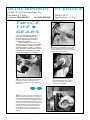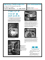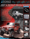
1
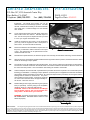
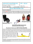
ADVANCE ADAPTERS INC.
P/N: RANGER OD
P.O. Box 247, 4320 Aerotech Center Way
Paso Robles, CA 93447
Telephone: (800) 350-2223
Fax: (805) 238-4201
PAGE 1 OF 11
Page Rev. Date: 06-19-12
The Ranger Torque Splitter Two-Speed Overdrive has been the answer to gear splitting for nearly
two decades. This unit was designed and developed by Warner Gear Corporation in the late 1960s. We
purchased the unit in 1975, and have built hundreds of overdrive units since that time. The design has
changed over the years, but the performance has stayed the same.
If you have a truck equipped with a 4 speed transmission and are having difficulty
keeping the engine RPMs at peak range, then you need a Ranger Torque
Splitter Overdrive. The Ranger simply provides a gear between each of
your existing gears and converts your 4 speed to an "8 speed". When used
as a gear splitter, you will be able to keep the engine RPM loss at a
minimum, thus preventing the usual winding and lugging of the 4 speed
transmission and engine. This works great for both diesel and gas pickup trucks.
With your engine coupled to the Ranger Torque Splitter Overdrive, your power can
now be efficiently utilized with less engine wear, maintenance & downtime, and
dramatically improve fuel economy. A typical example would be a Chevy truck with a V8
engine and a 4 speed transmission that has an engine RPM of 2500 when driving 60 m.p.h. in 4th gear. This same truck, when
equipped with the Ranger Overdrive and traveling 60 m.p.h. in 4th gear overdrive will have an engine RPM of 1825. This is a
drop of 27% in engine RPMs for the same highway speed.
The Ranger Torque Splitter Overdrive has been designed for maximum ease of installation and requires no special tools. The
front of the Ranger simply bolts directly to your existing bellhousing. Your 4 speed transmission indexes directly into the back
of the Ranger. You will be required to have your driveshaft shortened by your local driveline specialist. The Ranger is 7-1/2"
long and will require the relocation of your 4 speed transmission shift lever.
The internal design of the Ranger Torque Splitter Overdrive consists of a T98 synchronizer coupled with precision helical cut
gears. The gear assembly is mounted on roller & ball bearings that will provide a maximum torque range of 420 ft./lbs. Each
unit is furnished with a shift control handle that has been designed for use in most pickup trucks. The splitting of gears does require
shifting of both the stock 4 speed shift lever and the Ranger shift lever. The clutch must be used when shifting the unit.
RANGER II SPEED
The Ranger is currently available in only a 27% OVERDRIVE ratio.
The Ranger is compatible with all manual transmissions whether in 2WD or 4WD. Since the location is ahead of the transmission
and transfer case, the overdrive and gear splitting capabilities can be used in 4WD. The installation of the Ranger in your vehicle
will not require the continual use of all eight forward gears. Depending on your requirements, you need not always use all eight
gears. A good example would be when you are in city traffic where you may choose to use only four gears--the choice is yours.
Whether loaded or unloaded, on the highway or in the city, the Ranger offers you the opportunity for a great investment that makes
your truck fit your driving requirements.
SPECIAL NOTE:
The components packaged in this kit have been assembled and machined for specific type of conversions. Modifications to any of the components
will void any possible warranty or return privileges. If you do not fully understand modifications or changes that will be required to complete your conversion, we
strongly recommend that you contact our sales department for more information. This instruction sheet is only to be used for the assembly of Advance Adapter
components. We recommend that a service manual pertaining to your vehicle be obtained for specific torque values, wiring diagrams and other related equipment. These
manuals are normally available at automotive dealerships and parts stores.
ADVANCE ADAPTERS INC.
P/N: RANGER OD
P.O. Box 247, 4320 Aerotech Center Way
Paso Robles, CA 93447
Telephone: (800) 350-2223
Fax: (805) 238-4201
PAGE 2 OF 11
Page Rev. Date: 11-14-14
RANGER III MODELS & SPECIFICATIONS
CHEVROLET & GMC:
Part No.
Description
Index Dia.
All GMC and Chevrolet manual transmissions have a
bellhousing index hole of 4.686" or 5.125". Car-type
760001M-27 27% Overdrive Transmission
4.686"
transmissions and truck transmissions 1967 & earlier
require the 4.686" index, while trucks 1968 to 1988,
760002M-27 27% Overdrive Transmission 5.125"
require the 5.125" index. The clutch spline on all GMC
transmissions must be 1-1/8" 10 spline. In 1993, the
New Venture 5 speeds required a special rear plate and
bolt pattern requirements. Note: These units are only for the Chevy 4 speed transmissions and will bolt directly to the 4 speed and
bellhousing with only minor modifications. Driveline and floorboard modifications are required.
FORD MOTOR COMPANY:
All Ford manual transmissions have a bellhousing index
hole of 4.848" or 5.125". The car-type transmissions
and most truck-type transmissions have the 4.848"
index size. There are a few early model trucks that have
the 5.125" index. The input shaft clutch spline must be
1-1/16" 10 spline and have a minimum stickout length of
6-1/2". Note: These units are only for the Ford 4 speed
Part No.
Description
Index Dia.
760010M-27
27% Overdrive Transmission
5.125"
760014M-27
27% Overdrive Transmission
4.848"
transmissions and will bolt directly to the 4 speed and bellhousing with only minor modifications. Driveline and floorboard modifications are
required. Note: We do not offer a 7-1/2"long input shaft option.
TOYOTA LAND CRUISERS:
The use of the Ranger transmission in the Toyota Land
Cruiser V8 Chevy engine conversions has become quite
popular when being used with the stock Toyota 4 speed
transmission. When used with a new V8 engine conversion, driveshaft modifications and special bellhousing
adapters can be eliminated. Note: The earlier 3 speed Land
Part No.
Description
Index Dia.
760024M-27
27% O.D. Trans-GM V8 Eng.
to Toy L/C 4 Speed
5.125"
*FORD V8 UNITS AVAILABLE - Special Order
Cruiser can be mated to the Ranger Torque Splitter by using a special retainer, P/N 716222, with Overdrive P/N 760001M-27.
Special Note: The Ranger can be installed on 1987 and newer Land Cruisers. On these applications, we have found a few odd size input shaft
bearings that Toyota used. In order to use our overdrive unit, the front input shaft bearing of your transmission must be measured. (This will verity what
bearing index is necessary - a 3.544" diameter is standard). If your bearing diameter is 3.625", a special rear plate can be machined for this application.
SPECIFICATIONS:
Unit Weight ........................................ 80 lbs.
G.V.W. Rating .................................... 25,000 lbs.
Torque Capacity ....................... 420 ft./lbs
Oil Capacity .............................. 1.65 quarts
RANGER TORQUE SPLITTER/OVERDRIVE ONE (1) YEAR LIMITED WARRANTY
The manufacturer warrants this product against material defects and faulty workmanship for a period of one (1) year from the time of shipment. We do not
offer any type of labor allowance, and all warranty claims are subject to inspection by Advance Adapters. It is the customers responsibility to return possible
warranted parts to Advance Adapters. The customer will be refunded for shipping costs incurred if the product is found faulty. We reserve the right to repair
or replace any product. All returns must have a Return Goods Authorization Number (RGA#). Please call 1-800-350-2223, and our sales
department can assist you. Warranty is void if proper gear lubricates are not used, the proper oil levels are not kept, the product has not been properly installed,
and or installation instructions have not been followed.
ADVANCE ADAPTERS INC.
P/N: RANGER OD
P.O. Box 247, 4320 Aerotech Center Way
Paso Robles, CA 93447
Telephone: (800) 350-2223
Fax: (805) 238-4201
PAGE 3 OF 11
Page Rev. Date: 12-28-99
VEHICLE INSTALLATION PROCEDURES
CHEVY, GMC, FORD & TOYOTA L/C
INSTALLATION PROCEDURES:
READ THESE INSTRUCTIONS CAREFULLY BEFORE BEGINNING!
1.
Disconnect the battery cable.
2.
Unscrew the molding at one door so that the carpet or mat may be
folded to the opposite side for access to the shifter.
3.
Unscrew the boot and slide it upward for access to the top of the
transmission. Remove the shift handle knob and shift lever boot for
the transmission and (if a 4WD) the transfer case.
4.
Remove the shift lever out of transmission by removing the stamped
metal piece from the base of the stick. NOTE: Some models simply
STANDARD BELLHOUSING
"A" DIA.
OVERDRIVE OR
UNDERDRIVE
unscrew, while others come apart by pushing down and turning
approximately 1/4" counterclockwise. On Borg Warner T18 transmissions found in some Ford products, it is necessary to remove a
small pin in the left side so that it does not fall into the transmission.
"A" DIA.
5.
Place a clean rag in the top of the transmission so that dirt does not
get in during removal and reinstallation.
6.
With the mat or carpet pulled to one side, remove the screw and bolts
from the tunnel housing and detach it. (Greater accessibility can be
gained by removal of the seat).
7.
Jack up the vehicle and support solidly. Be sure to block any wheels
remaining on the ground. CAUTION: Never go under a vehicle
that is not solidly supported. Adequate jack stands are recommended. Before beginning work, always test a raised vehicle
carefully to be certain there is no danger that the vehicle will
fall.
8.
Unbolt the U-Joints and remove the rear driveshaft (on 4WD
vehicles, the front driveshaft must also be removed). The rear
driveshaft must be shortened 7-1/2", and the front driveshaft must
be lengthened respectively. (On Land Cruiser installations with a
GM V8, no driveline modifcations are required).
9.
Disconnect the speedometer cable. Because of the additional
length of the Ranger, it may necessary to lengthen the speedometer
cable. This may be accomplished in some cases by rerouting the
cable. If that isn't possible, then it may be necessary to have a new
cable made.
10.
Disconnect the backup light switch wires and the 4WD indicator light
wires on the transmission if your vehicle is so equipped. CAUTION:
Before proceeding any further, determine if the rear of the
engine is supported by mounts on the bellhousing or to the
STOCK TRANS.
2WD OR 4WD
SIMPLE INSTALLATION
ADVANCE ADAPTERS INC.
P/N: RANGER OD
P.O. Box 247, 4320 Aerotech Center Way
Paso Robles, CA 93447
Telephone: (800) 350-2223
Fax: (805) 238-4201
PAGE 4 OF 11
Page Rev. Date: 04-16-02
transmission. On most models, the rear of the engine and
transmission are supported by a crossmember bolted to the
frame, and then to the transmission with a cushion between
the crossmember and the transmission. It is essential that the
rear of the engine be properly supported before proceeding.
11.
When you are certain that the rear of the engine is firmly supported,
remove the bolts in the crossmember and take it off.
12.
Place a transmission jack under the transmission and secure it
firmly to the transmission. CAUTION: Failure to secure the
CLEAN
transmission to the jack, could result in serious bodily injury.
13.
When the jack has been securely fastened to the transmission,
remove the four bolts holding the transmission to the bellhousing.
14.
Remove the transmission. This is an excellent opportunity to check
the condition of the clutch disc, pressure plate, throw-out bearing,
and pilot bearing. Replace worn parts if necessary.
15.
Clean the transmission input shaft thoroughly. Measure the opening
in the bellhousing carefully, and then the outside diameter of the
bearing retainer on the Ranger Overdrive. SEE THE ILLUSTRATIONS marked "A". If the bearing retainer size is smaller or
"A" DIAMETER
larger then the opening in the bellhousing, please contact us
toll free at 1-800-350-2223. Both bearing retainers must fit snugly
for proper alignment of the transmission to the Ranger, and the
Ranger to the bellhousing.
16.
"A" DIAMETER
Remove the front bearing retainer on the original transmission
carefully so as not to tear the gasket. Also, check the oil seal in the
base of the retainer and replace it if necessary. (The oil seal is not
supplied in the Ranger kit. The snout of the retainer must be cut off
and the seal must be retained. The normal cutoff location is .750".
However, we have had a customers require a longer length to retain
the stock seal. Make sure you cut enough off so that the snout does
not bottom out in the back of the Ranger.
REMOVE
.750" (3/4")
"A" DIA.
Reinstall the retainer on the original transmission using the original
gasket and bolts (without lock washers). Lock washers will raise the
bolt head heights enough to cause severe damage and interference.
We recommend that you use "BLUE LOCTITE" for the bolts in place
of lock washers.
On Land Cruiser 4 speed installations, the Ranger uses the transmission front bearing for alignment. This step, as mentioned above,
is not necessary. Simply remove the front retainer and clean the front
of the transmission. On Land Cruiser 3 speed transmissions, our
bearing retainer P/N 716222 and seal P/N 716719 should be
used. The snout on this retainer must be shortened as list above.
SILICONE AROUND
RETAINER DIAMETER
CUT OFF BEARING RETAINER
INSTALLED ON TRANSMISSION
WITH SEAL STILL IN POSITION
SPECIAL NOTE:
The components packaged in this kit have been assembled and machined for specific type of conversions. Modifications to any of the components
will void any possible warranty or return privileges. If you do not fully understand modifications or changes that will be required to complete your conversion, we
strongly recommend that you contact our sales department for more information. This instruction sheet is only to be used for the assembly of Advance Adapter
components. We recommend that a service manual pertaining to your vehicle be obtained for specific torque values, wiring diagrams and other related equipment. These
manuals are normally available at automotive dealerships and parts stores.
ADVANCE ADAPTERS INC.
P/N: RANGER OD
P.O. Box 247, 4320 Aerotech Center Way
Paso Robles, CA 93447
Telephone: (800) 350-2223
Fax: (805) 238-4201
PAGE 5 OF 11
Page Rev. Date: 12-28-99
17.
Fasten the Ranger securely to the transmission jack.
18.
Bolt the Ranger unit into place using the bolts supplied. On some
models, it may be necessary to modify the floorboard slightly to
clear. The bolts on the left side of the unit will need to be started into
the bellhousing before the unit will fit. NOTE: Do not suck unit up
with the bolts.
19.
Run a paper-thin layer of silicone sealer on the rear plate and next
to the retainer to seal off any oil that might transfer between the two
units. Without the silicone sealer, you will have oil leakage between
the two units. The silicone must be wet while bolting the transmission to the overdrive. NOTE: An excess amount of silicone can
cause misalignment of these units. This can cause the unit to pop
out of gear, excessive wear, and ultimately will void the warranty.
20.
Using the transmission jack, bolt the original transmission to the
Ranger using the stock bolts.
21.
With the transmission jack still in place, check the position of the
rear crossmember (if you vehicle is so equipped). If the original
transmission was supported by this crossmember, it will be necessary to reposition it on the frame 7-1/2" further back. The relocation
is fairly simple on most applications.
22.
Reinstall the rear crossmember and secure it firmly to the frame and
transmission. CAUTION: Check all connections thoroughly
TRANSMISSION OR TRANSFER
CASE CROSSMEMBER
SUPPORTS
INSIDE FRAME
PERCH MOUNT
before lowering the transmission jack. Failure to do so could
result in bodily injury.
23.
If it was necessary to remove the exhaust system, make all
necessary modifications and reinstall. On some models, the
emergency brake cables are supported by rods that hook to the
crossmember. When the crossmember is relocated back 7-1/2",
you should purchase a cable clamp to take up the excess slack.
24.
Now, reconnect the speed-o-meter cable and backup light switch
wires and 4WD indicator light wires where applicable. 4WD models
will possibly need the 4WD shift handle bracket modified. Ford and
some Chevy vehicles will be able to use stock speed-o-cables.
25.
Reinstall the shortened drive shaft and be certain the bolts on the
carrier bearing and the rear "U"-joint are tight. On 4WD vehicles, the
new front driveshaft lengthened 7-1/2" is now reinstalled with special
attention to tightening the bolts on the front differential and the
transfer case flange.
26.
Before the tunnel can be installed, it must be modified with either a
sabre saw or air chisel. CAUTION: Use safety glasses to avoid
REAR CROSSMEMBER VARIES IN DESIGN.
THEY WILL REQUIRE RELOCATION 7-1/2"
FURTHER BACK.
injury while working with any of these power tools listed.
Cut a new shifter hole approximately 7-1/2" from your main 4 speed.
On manual shifter units, this will also be a good time to cut the hole
for the chrome shifter handle. The hole for the handle on your
Ranger should allow for mounting the boot screws to the tunnel or
OIL FILL PLUG
"A" DIAMETER
ADVANCE ADAPTERS INC.
P/N: RANGER OD
P.O. Box 247, 4320 Aerotech Center Way
Paso Robles, CA 93447
Telephone: (800) 350-2223
Fax: (805) 238-4201
PAGE 6 OF 11
Page Rev. Date: 03-02-12
floorboards. The handle hole location can now be
determined from the actual Ranger position. On 4WD
vehicles, it will also be necessary to relocate the transfer
case shifter hole, or extend linkage to fit new transfer
case location.
27.
Cover original transmission hole with sheet metal using
sheet metal screws and silicone. Reinstall carpet or
mat. You can use a piece of carpet from under your seat
to cover your original transmission hole.
28.
Install the original boot and screw it to the floorboard.
(You may cover the original hole with a small piece of
sheet metal. All cracks should be siliconed).
29.
Remove the shift lever and reinstall the carpet or mat. At
this point, you will have to make a new hole in the carpet
or mat. The original hole can be patched from excess
material beneath the seat.
30.
Reinstall the 4 speed shift lever, the shift lever pin (if it was removed), the shift switch and wiring, and the shift knob.
31.
With the stock four-speed shifter handle installed and the original boot back in position, all that remains is the shifter
handle for the Ranger Torque Splitter.
32.
The handle can now be installed onto the handle bracket. There are two positions that the handle can be bolted to.
The front two should be used when the handle needs to be further forward and the back two when the driver uses
the seat in the back position. Use lock washers when bolting the handle to the bracket.
33.
Advance Adapters recommends that a special break-in procedure be used for a period of 15 to 30 minutes prior to
finalizing your installation. The Ranger Torque Splitter is a precision piece of equipment that has been assembled
with precision bearing sand brass synchronizers. By using this simple break-in procedure, all of the gears and the
bearings will be assured of maximum life. The procedure would be to simply install 1-1/2 quarts of regular 30
wt. motor oil and drive the vehicle for approximately 1530 minutes. Drain the motor oil.
34.
Refill the Ranger with a high performance gear synthetic
lube (or equivalent). Viscosity rating on the oil (Mobile,
Valvaline, Shell, etc.) should be SAE75W-90.
Ranger Torque Splitter installed with a GM
SM465 transmission.
CAUTION: Failure to fill transmission and Ranger
Torque Splitter with oil, will void all possible warranty claims. Double check your oil level!!
WARNING: To properly change gears, the clutch MUST
BE DISENGAGED. Warranties will be voided on units
shifted improperly.
Ranger Torque Splitter
Assembly Kit
SPECIAL NOTE:
The components packaged in this kit have been assembled and machined for specific type of conversions. Modifications to any of the components
will void any possible warranty or return privileges. If you do not fully understand modifications or changes that will be required to complete your conversion, we
strongly recommend that you contact our sales department for more information. This instruction sheet is only to be used for the assembly of Advance Adapter
components. We recommend that a service manual pertaining to your vehicle be obtained for specific torque values, wiring diagrams and other related equipment. These
manuals are normally available at automotive dealerships and parts stores.
ADVANCE ADAPTERS INC.
P/N: RANGER OD
P.O. Box 247, 4320 Aerotech Center Way
Paso Robles, CA 93447
Telephone: (800) 350-2223
Fax: (805) 238-4201
PAGE 7 OF 11
Page Rev. Date: 06-19-12
PARTS
LISTING
PART #
DESCRIPTION
Item#
761074
723705
761028
761029
761023
761301
761307
761302
761045
761124-A
723110
761044
723752
761309
761033
761037
761034
761026
761005C
761005F
761024
761064
720015
761098
761027
761015
761016
761019
723113
723119
*761065
761096
SHIFT FORK (New Style)
1
3/8"-24 NF NUT
5
SIDE COVER GASKET
7
SPRING (Shift Fork)
8
3/8" STEEL BALL (Ford & Cover)
9
NEW STYLE RANGER III (5/88)
10
SIDE COVER GASKET-RAN III
11
SIDE COVER HANDLE CAP
12
"O"-RING SEAL (Shift Rail Seal)
13
FILL PLUG
15
5/16"-18 x .75 S.H.C.S.
16
SHIFT RAIL
17
SET SCREW FOR SHIFT RAIL
18
ZERKFITTING
20
CHEVY & GM 5.125" DIA.
21
4SP TOYOTA L/C 5.038" DIA.
21
FORD 4.848" DIA.
21
REAR PLATE GASKET
22
CHEVY & GM CASE
23
FORD CASE
23
FRONT COVER GASKET
24
FRT. LOW. BRG. COV. PLATE
25
10"-24 x .375" LG. F.H.C.S.
26
SEAL-C/R # 12363
27
GASKET
28
CHEVY & GM 4.686"
29
CHEVY & GM 5.125"
29
FORD 4.848"
29
S.H.C.S. 5/16"-18 x 3/4"
30
5/16"-18 NC x 1.25" H.H.C.S.
31
(discon't) DRIVE SLEEVE BUSHING
INPUT SHAFT BEARING (7/88)
32
(BA-2212-ZOH-MFG-1K0)
*Note: Units having a bushing will require the input shaft to be
I.D. ground to fit the new roller bearing.
761053
761054
761069
761093
CHEVY & GM SPLINE 1-1/8" 10
FORD SPL. 1-1/16" 10 x 6-1/2"
OIL SLINGER - BW #T90A-136A
BEARING FOR INPUT SHAFT
(BCA # N1308LOB)
33
33
34
35
PART #
DESCRIPTION
761083
761081
761092
SNAP RING
SNAP RING
BRG. FOR LOW. CLUSTER GEAR
(BCA # 306L)
27% O.D. CLUSTER GEAR
36
37
38
40
761052
FRT.BRG.FORCLUSTERGEAR
(BCA # M-1305GTV)
SNAP RING
REAR BRG. FOR DRIVE SLEEVE
(BCA # 211SSL)
STEEL BEARING RETAINER
CHEVY/GM DRIVE SLEEVE
1-1/8" 10 (27% O.D. - 17% U.D.)
FORD DRIVE SLEEVE
(27% O.D. - 17% U.D.)
27% O.D. GEARS - 23 TEETH
761070
300372
300370
300371
300373
761070E
761084
761124
761105
761073
723721
723704
723139
761306
761304
761305
761313
761314
761000
761000NS
COMPLETE SYNCHRO ASSY.
SYNCHRO DOGS-HOLLOW (Ea.)
BRASS SYNCHRO RING (Ea.)
SLIDER RING
SYNC. DOG WIRE SPRINGS (Ea.)
SYNCHRO HUB
SNAP RING
INSPECTION COVER
HANDLE
SHIFT KNOB
3/8"-16 NC x 1" LG. S.H.C.S.
7/8" LOCK WASHER
5/16"-18 NC x 1.50" LG. S.H.C.S.
PIN BAR ASSEMBLY
BALL DETENT BAR
HANDLE MOUNTING SHAFT
HEXNUT
COTTERPIN
GASKET AND SEAL SET (Early)
GASKET AND SEAL SET (Ranger III)
761102
761091
761085
761090
761103
761001
761002
Item#
39
41
42
43
44
44
45
46
47
48
51
52
64
65
67
68
69
70
72
P/N: RANGER OD
P.O. Box 247, 4320 Aerotech Center Way
Paso Robles, CA 93447
Telephone: (800) 350-2223
Fax: (805) 238-4201
PAGE 8 OF 11
Page Rev. Date: 04-06-00
Ranger III - Components
1989 & UP
ADVANCE ADAPTERS INC.
ADVANCE ADAPTERS INC.
P/N: RANGER OD
P.O. Box 247, 4320 Aerotech Center Way
Paso Robles, CA 93447
Telephone: (800) 350-2223
Fax: (805) 238-4201
PAGE 9 OF 11
Page Rev. Date: 01-05-00
A
1
The overdrive unit arrived
bolted to a piece of
plywood to protect it from
damage during shipping.
2
The new overdrive and
old transmission/transfer
case package (previously
removed as a set are shown
aligned in the position they
will be reinstalled. The Dana
20 transfer case was mated
to the NP435 transmission
using Advance Adapters'
part #711114 adapter plate.
PHOTOGRAPHY: MICHAEL VANVAKARIS
dvance Adapters' Ranger Torque
Splitter is a two-speed auxiliary
transmission that, depending on
your needs, can be ordered in either an
overdrive or underdrive model. The
overdrive unit will supply a 27-percent
change in gearing, and the underdrive
model offers a 17-percent shift. Don't let
the name Ranger mislead you, this unit
can be mounted on almost any manual
transmission-equipped vehicle. Built
inside an aluminum case, the Torque
Splitter provides a four-speed vehicle with
eight forward and two reverse gears.
When four-wheel-drive is engaged, 16
forward and four reverse gears are
available. The advantages offered by an
auxiliary transmission such as this are
numerous: the ability to have twice the
gears to choose from while off-highway,
extra-low gears to get a towed load such
as a trailer rolling easier, and a set of gear
ratios that keeps highway driving with tall
tires and tall gears from being a gasguzzling odyssey.
Disconnecting the vehicle's battery is
always a good idea before beginning any
aftermarket equipment installation, and the
Torque Splitter's instructions suggests
doing so. Remove both front seats and
carpet for access to the transmission
tunnel, and remove the gear levers.
Remove the tunnel housing, and the
transmission with a rag to keep dirt out
during removal and reinstallation. Jack the
vehicle up and solidly support it. Remove
both driveshafts; the front shaft will have to
be lengthened 7-1/2 inches, the rear
shortened the same measurement and
both shaft must be rebalanced.
zz
zz
T
TW
WI
IC
CE
E
T
TH
HE
Ez
z
GEARS
GEARS
INSTALLING ADVANCE
ADAPTERS' TORQUE SPLITTER
OVERDRIVE By Stuart Bourdon
4-Wheel & Offroad Magazine, Copywrite & printed with permission of Petersen Publshing Company, L.L.C.
ADVANCE ADAPTERS INC.
P/N: RANGER OD
P.O. Box 247, 4320 Aerotech Center Way
Paso Robles, CA 93447
Telephone: (800) 350-2223
Fax: (805) 238-4201
PAGE 10 OF 11
Page Rev. Date: 01-05-00
T
TW
WI
IC
CE
E
T
TH
HE
Ez
z
GEARS
GEARS
Disconnect the speedometer cable, which, in
some cases, must also be lengthened or
rerouted to span the 7-1/2-inch rearward
movement of the transmission created by
installing the Torque Splitter.
Advance Adapters recommends a 15- to
30-minute break-in period for the Torque Splitter
before extended use. The break-in procedure
suggested is to fill the unit with 1-1/2 quarts of
regular 30-weight motor oil and drive the vehicle
under light duty. Then drain the motor oil and
refill the Torque Splitter with 1.65 quarts of
3
A hole was cut in the floorboard to make
room for the overdrive shift lever and allow for
the rearward (7-1/2 inch) displacement of the
transmission/transfer case assembly and its two
shift levers.
4
After carefully removing the front bearing
retainer from the NP435 transmission so as
not to tear the gasket (which must be reused),
measure the retainer (from the back of the flange
forward) and cut off all but 3/4-inch.
6
Silicone sealer was used around
the edge of the retainer where it
meets the transmission case so that oil
would not pass between the transmission and the Torque Splitter.
zz
zz
5
Use a T-square to measure and scribe the cut
line on the front bearing retainer. This measure
must be accurate, because if the bearing retainer is
more than 3/4-inch thick, the Torque Splitter will be
damaged. The transmission front bearing retainer
was then remounted to the transmission case using
the original gasket and bolts, but without the lock
washers, since the lock washers can raise bolt
head heights enough to cause damage to the
Torque Splitter. Use Blue Loctite in place of lock
washers.
4-Wheel & Offroad Magazine, Copywrite & printed with permission of Petersen Publshing Company, L.L.C.
ADVANCE ADAPTERS INC.
P/N: RANGER OD
P.O. Box 247, 4320 Aerotech Center Way
Paso Robles, CA 93447
Telephone: (800) 350-2223
Fax: (805) 238-4201
PAGE 11 OF 11
Page Rev. Date: 07-16-14
T
TW
WI
IC
CE
E
T
TH
HE
Ez
z
GEARS
GEARS
high-grade gear lubricant, such as SAE 75W-90.
Our installation shown here was performed
on a '71 Ford Bronco featuring a NP435 fourspeed manual transmission. You should read all
installation and service instructions supplied by
Advance Adapters before beginning installation.
7
9
Because the Torque Splitter is mounted between
the bellhousing and the transmission, the
transmission is moved rearward 7-1/2 -inches upon
reinstallation. Consequently, the rear powertrain
crossmember supporting the transmission must move
back the same distance. In this case, the stock
crossmember brackets were welded to the frame at
the new location, still allowing removal of the
transmission for service by simply removing the bolts
that go through the crossmember.
10
After the Torque Splitter was secured
to a transmission jack, it was bolted
into place on the bellhousing.
With the Torque Splitter, transmission and
transfer case all in place, three shift levers
protrude from the hole in the floor. The levers can
be shortened to suit the driver, and after measuring
the distance of full throw, forward and rearward, of
the three levers, a sheetmetal transmission tunnel
plate can be manufactured by a custom fabrication
shop.
8
After fastening the
transmission and
transfer case to a
transmission jack and
securing the mass with a
chain. The transmission
is bolted to the Torque
Spliter.
zz
zz
SOURCES
used to compile this story
Advance Adapters, Inc., Dept. 4WOR,
P.O. Box 247, Paso Robles, CA 93446,
805/238-7000
Michael's Welding & Design, Dept.
4WOR, 13625 Manhasset Rd. #1,
Apple Valley, CA 92308, 619/240-0112
4-Wheel & Offroad Magazine, Copywrite & printed with permission of Petersen Publshing Company, L.L.C.