1
HOT BEVERAGE MERCHANDISER MODEL 213 OPERATING SERVICE MANUAL W
~
DO NOT REMOVE
(Qb
MANUAL FROM MACHINE
AUTOMATIC
Automatic Products 213DC V2.0 9/00
r
PRODUCTS
A Crane Co . Company
PART # 37012
Express Warranty
Automatic Products international ltd. (APi) expressly warrants these automatic merchandisers (the ·Unir),
manufactured by it, to be free under nonnal use alld service from defects in material or wOrXmanship for a period of
two (2) years from the date of delivery of this Unit to the original purchaser. This warranty extends only to the Original
purchaser of the Unit. The exclusive remedy for this warranty is limited to the repair or replacement, at APi's sole
option, of any part or parts of the Unit that are returned to APi or to the authorized dealer or distributor of APi from
whom the unit was purchased with all transportation charges prepaid, and which, on APi's examination, shall,
conclusively appear to have been defective. This warranty does not:
a. extend to any Unit, or part thereof, that was subjected to misuse, neglect, or accident by other than APi after
its delivery to the original purchaser;
b. extend to any Unit, or part thereof, that was modified, altered, incorrectly wired or improperly installed by
anyone other than APi or used in violation of the instructions provided by APi;
c. extend to a Unit which has been repaired or altered by anyone other than APi or authorized
dealer/distributor;
d. extend to a Unit which has had the serial number removed, defaced or otherwise altered;
e. extend to plastic or glass windows, lamps, fluorescent tubes and water contact parts;
f. extend to any unit used outdoors
g. extend to accessories used with the Unit that were manufactured by some person or entity other than APi.
API DISCLAIMS ALL OTHER WARRANTIES OF ANY KIND AS TO THE UNIT AND ALL WARRAN1'IES OF ANY
KIND AS TO ANY ACCESSORIES, THIS DISCLAIMER OF WARRANTIES INCLUDES ANY EXPRESS
WARRANTIES OTHER THAN THE LIMITED WARRANTY PROVIDED ABOVE AS TO THE UNIT AND ALL
IMPLIED WARRANTIES OF MERCHANTABILITY AND FITNESS FOR A PARTICULAR PURPOSE AS TO'rHE
UNIT AND ANY ACCESSORIES. LINDER NO CIRCUMSTANCES SHALL API BE RESPONSIBLE FOR ANY
INCIDENTAL, CONSEQUENrlAL OR SPECIAL DAMAGES, LOSSES OR EXPENSES ARISING FROM OR IN
CONNECTION WITH THE USE OF, OR THE INABILITY TO USE, THE GOODS FOR ANY PURPOSE
WHATSOEVER, No representative of APi or any other person is authorized to assume for APi, or agree to on the
behalf of APi, any other liability or warranty in connection with the sale of this Unit.
APi reserves the right to make any changes or improvements in its products without notice and without obligation,
and without being required to make corresponding changes or improvements in Unit theretofore manufactured or
sold.
AUTOMATIC
-LIa-~~~~,~.~~~".,
300 Jacksonville Rd . • Warminster. PA. • 18914
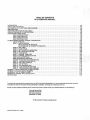
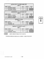
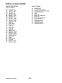
TABLE OF CONTENTS AP 213 SERVICE MANUAL . INTRODUCTION ....... .. .. . ........ .. . .. .. ....... . .. . .... ... .. , . . . . . . . . ... . ... .. . . . ... .. .. .. . . . .. . .. ... . .
HOW TO USE THIS MANUAL ... . ......... . .... .. . .......... ... ... . .... . .. . ....... . ..... .. ... ..... .. . .......
FEATURES OFAP 213 HOT DRINK MERCHANDiSER. ........ .. ... .. . ................ . .. .. . ... . ... .. .. .........
SPECIFICATIONS . .. ... ... ............ ... ....... . . .. . ..... .... ........ ... .... . . . ..... ..... .. ... . . . . ... . . . . .
SOFTWARE IDENTIFICATION AND LABELS . ................ . ..................... .. ...... ........ . ... . ..... . .
INSTALLATION AND SET-UP INSTRUCTIONS ....... . .. .... . . . ........... . . . . ... .. . ..... . . .. . ... . . . . .. . . . ... . . .
CANISTER RACK INDEX CHART . ... .. . .... . . ........ .. .... . . . . . ... . ... .... . . ... .. . ..... .... .. •.. .... . .. . ... .
RACK CONFIGURATION f2J ••. •. ••.• . .•• .•. ••••• •... • • . • .•• • •••••••••• •• ••.•••• • •• •••••• . . • ... .. . .• .
RACK CONFIGURATION 1 ... . ........ ..... . ... . .. .... ... .. .. ...... . ......... . .. ........ . .. .. . .... .
RACK CONFIGURATION A ....... . ...... .. . ......... . .. .... .. ... . . ......... ....... ... . .. .. . . . . .....
RACK CONFIGURATION 2' .. .. . . . ..... . . ... ... ..... . ... .... .. ......... . . ... . ..... .. ... . .. . . . .. . ....
213 ELECTRONICS CONTROL SYSTEM -INTRODUCTION.. . . . . . . . . . . . . . .. . . .. . . . ... .. . . . ... . . . . . . .. . . .. .. . .....
USE OF KEYBOARD .... ... ....... ... .. ... ....... .. ... . ................... ...... ... .. . .. .. .. . .. . ..
MODE 1 - DISPLAY REPORT . .................................. ... .......... ... . . ...... ,.. . ........
MIS FLOWCHART BY PRICELINE . . . . . . . . . . . . . . . . . . . . . . . . . . . . . . . . . . . . . . . . . . . . . . . . . . . . . . . . . . ..
MIS FLOWCHART BY PRODUCT INFORMATION. . . . . . . . . . . . . . . . . . . . . . . . . . . . . . . . . . . . . . . . . . . . . . ..
MODE 2 - TEST VEND . . . . . . . . . . . . . . . . . . . . . . . . . . . . . . . . . . . . . . . . . . . . . . . . . . . . . . . . . . . . . . . . . . . . . . . . . . . ..
MODE 3 - FLUSH CYCLE ... ... . . ... ... .... .. ... . ..................... : . . . . . . . . . . . . . . . . . . . . . . . . . . . ..
MODE 4 - SET PRICES FOR LARGE DRINK. . . . . . . . . . . . . . . . . . . . . . . . . . . . . . . . . . . . . . . . . . . . . . . . . . . . . . . . . . . .
MODE 5 - SET PRICE REGULAR SIZE ...............................................................
MODE 6 - DIAGNOSTICS. . . . . . . . . . . . . . . . . . . . . . . . . . . . . . . . . . . . . . . . . . . . . . . . . . . . . . . . . . . . . . . . . . . . . . . . . ..
MODE 7 - CHANNEL TIMED TeST ...................................................................
MODE 8 - CHANNEL CONTINUOUS TEST .............. . . . . . . . . . . . . . . . . . . . . . . . . . . . . . .. . . . . . . . . . . . . . . . ..
MoDE 9-UPLOAD SETIINGS ... ... ..... ........................................................... .
MODE 10-DOWNLOAD SETIINGS .................•... '..................................... . . .. .... . .
MACHINE TO MACHINE UPLOAD/DOWNLOAD . . . . . . . . . . . . . . . . . . . . . . . . . . . . . . . . . . . . . . . . . . . . . . . . . . . . . . . ..
MODE 11 - MACHINE CONFIGURATION ..............................•...............................
MODE 12 - SET TIME CHANNELS ........ . ... ................ . ..... ... ............................. ...
MODE 13 - SET OPTIONS. . ... . . ...... . .. . ... . . . . . . . . . . .. . . . . . . . .. . . . .. ..... . . . ... . . . . . .. .. .. . ... ..
MODE 14 - SET DISCOUNT BITS ................................ . .................... . ....... . . ... . .
MODE 16 - LOAD STANDARD SETTINGS ...................................................... . ......
MODE 17 - PROGRAMMING USER MESSAGE.......... ......... .. .. . .. ............... .. ... . ....... . ..
APPENDIX I - GRAM THROWS AND WATER VOLUMES . . . . . . . . . . . . . . . . . . . . . . . . . . . . . . . . . . . . . . . . . . . . . . . . . . . . . . . . ..
APPENDIX II: 213 LOGIC SWITCH NUMBERS . .. ... ... . . . .. . ... . ......... . .............. . ... . .. .. ..............
APPENDI)$.III: "OUT OF ORDER" CODES .. ... .. ......... ....... . ............................... '" .. . ... .. ....
APPENDIX IV: CHANNEL APPLICATION CHART . . . . . . . . . . . . . . . . . . . . . . . . . . . . . . . . . . . . . . . . . . . . . . . . . . . . . . . . . . . . . . ..
SERVICE INDEX .. .... ... . ... .. .... ............................................................ .'.. ...... . .
To achieve the most trouble-free operation from your AP213 Hot Drink Merchandiser. it is recommended that this service manual be
thoroughly read and the Instructions followed pertaining to InstaliaHon. servicing and maintaining of the unit.
Should you have questions pertaining to this manual or the vendor. please contact your APIIRMI distributor or write directly to:
Technical Service Dept.
Automatic Products Inti.
300 Jacksonville Road
Warminster, PA 18974
© 1994 Automatic Products International. ltd
Automatic Products 213 V1 .6 0798
1.01 1.01 1.02 1.02 1.03 1.05 1.07 1.08 1.14 1.20 1.25 2.01 2.02 2.03 2.04 2.05 2.03 2.06 2.06 2.06 2.07 2.07 2.07 2.08 2.08 2.08 2.09 2.10 2.12 2.13 2.13 2.14 2.15 2.16 2.17 2.18 3.01 INTRODUCTION
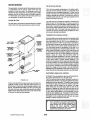
The Automatic Products 213 Dual Cup Hot Drink Merchandiser is the latest in state of the art vending
technology. The AP Model 213 combines the reliability, durability and simplicity of the time proven RMi hot drink
vendor with micro-electronics resulting in unsurpassed flexibility and adaptability to satisfy both yours and your
customer's needs. The selection panel features an overlay overa LED board which contains momentary selector
switches. This enhanced selector panel provides a maximum of seven prime selections of which five may feature
three strengths. Selections include fresh brewed coffee, regular and decaffeinated, chocolate, a Custom Select
Coffee preset for Cafe Mocha - a combination of coffee and chocolate, plus a minimum of one Soluble Gourmet
Coffee (SGC). Fresh brewed tea or soluble tea is also available in three strengths and each of the selections is
available with three levels of lightener, sugar or sugar substitute. Custom Select Coffee, which offers the
operator the ability to combine a number of ingredients already in the machine to produce a premium drink such
as Cafe Mocha or Balanced Blend'lltl or an additional SGC are also available as an added selection. The extreme
flexibility of the model 213 allows the customer to "Build A Drink" to their personal tastes. All selections can be
individually priced using a 24 volt controller type coin mechanism and bill validator, or can be adapted to use 110
volt equipment. The translucent canisters and the open canister rack design. including an improved dual outlet
exhaust system. allow for easy monitoring of product levels to maintain freshness, and ease of regular cleaning
to provide your customer with the best possible hot drink.
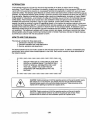
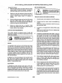
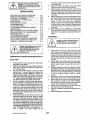
HOW TO USE THIS MANUAL
This manual is divided into three basic parts:
1. Introduction, features and installation
2. Electronic operation and mode descriptions
3. Service. operation and adjustments
The service section has its own Index. located on the first page of each section. In addition, the separate parts
manual also has a pictorial index located adjacent to the index. Each section contains in depth deSCriptions of
the material covered.
.
••••••••••••••••••••••••••••••••••
•
•
•
•
•
•
•
WATCH THROUGH OUT THE MANUAL FOR THIS
SPECIAL. DIAMOND MARK. THIS INDICATES A
POINT OF SPECIAL INFORMATION OR A HINT
THAT WILL ASSIST YOU IN SETTING UP,
OPERATING OR TROUBLESHOOTING THE
MACHINE.
•
•
•
•
•
•
•
••••••••••••••••••••••••••••••••••••
CAUTION: Certain procedures in both the operating section and the service section require
that voltage be on in the machine. Only trained personnel should perform this function.
Exercise extreme caution while performing these procedures. These procedures will be
marked with the lightning bolt symbol as It appears at left.,
CAUTION: Certain procedures in both the operating section and the service section
requires a qualified trained technician to perform the particular task at hand. These
procedures will be marked with the exclamation symbol as it appears at left.
Automatic Products 213 V1 .6 0798
1.01
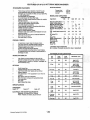
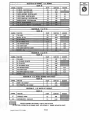
FEATURES OF AP 213 HOT DRINK MERCHANDISER SHIPPING WEIGHT ,
STANDARD FEATURES
o
o
o
o
o
o
o
o
o
o
o
o
o
o
Freeze-dried
Loose ground
Grinder
Total of seven primary selection of which five are
prime selections, each with three programmable
strengths plus chocolate and SGC or soup depending
on rack configuration.
Dual adjustable cup separators.
12 ounce brewer with fixed filter base.
Easy to use color coded selection buttons for variable
strength products.
Preset for either one or two cup sizes.
Improved high velocity exhaust system.
Over 840 selections possible.
Coffee strength variable by changing coffee throw.
ArtIficial sweetener available.
Variable strength additives.
Easy to change selection labels.
Selection lamps and audible tone feedback for touch
sensitive buttons.
Coins for the next vend can be Inserted before the end of the current vend. Auto flush every 12 hours
MODEL AND CAPACmES
Capacities Ibs.
Ingredient:
DG
G
Regular Coffee Beans 11
Decaf. Coffee Beans
5
Regular Ground Coffee Decaf. Ground Coffee
Soluble 'FD' Coffee*(2) Soluble 'FD' Decaf*(1) 1.5
1.5 Tea Leaf·Fresh brewed 2.5
2.5 or Instant*(1)
1.5
1.5 8
Sugar*(2)
Sugar Substltute*(1)
100z
4
Whltener*(2)
Chocolate (4)
12
SGC *(2)
4
4
Soup *(2)
All selections of each size Individually priced .
Two price levels for variable strength selections.
Separate discount pricing structure available.
Programmable winner mode
Forced vend and bill escrow features.
Full accountability Including discount cash meters, ten separate price line counters or accountability by beverage and size. o
GLG DH
LG
3.5
11
12 4.5 3
1.5 1.5 1.5
1.5
2.5
2.5
2.5
2.5 1.5
1.5
1.5
1.5 8
8
8
8
100z
4
12
4
4
100z
4
12
4
4
100z
4
12
4
100% 10 4
4
12
12 4
4
4
4
CUP MODELS AND CAPACITIES
User friendly scrolling display to help with the selection process and provide customer feedback. Programmable for stand-by "operator" messages, up
to 85 characters long.
Cup
Size
Large
Cabinet
Small
Cabinet
70z.
656 429 Manufacturer Cup #
Swt\' pvsn;
IMPSVR~70
8Y. oz.
OPTIONS
590 378 Swt"f PV588,
IMPSVR~80
ConI CUP 21o.2000AV
o
o
o
o
o
o
o
o
o
Fresh brewed tea
Whipped Soluble Gourmet Coffee (SGC)
USE YOUR OWN CUP option with or without discount feature 24V (standard) or 11 OV capability for coin mech or valldator Slow retum vend door dampener
MIS Information retrieval and upload/download
Cold water shot '
Kick plate
Bean hopper filler plate
80z. insul
350 251 Swt'l8XTX
90z. 552 356 Swt"f PV509, IMP SVR-0090 10 oz.
543 354 IMPSVR·10
120z. tall 533 341 IMP SVR~120A
12 oz. squat
552 352 IMP SVs-{)120 Swt\' PV512T Cont Cup 355-2000AV 12oz.
squat 334 228 International HM1200
120z. squat
549 366 Swt\' PV512
120zlnsul
tail-sQuat
230 158 Swt\' V12TX
12oz. insul
321 203 Swt\' V12X
SPECIFICATIONS DIMENSIONS: Height 72"
Depth: 31"
Width: 38" ELECTRICAL AND WATER REQUIREMENTS:
Electrical : 120 Volts; 60 Hz; 16 Amps
Water: Potable cold water, 20 psi minimum
Automatic Products 213 V1 .6 0798 1.02
Fe
11 .5 * Canisters may be expanded (#) • number of canister levels (Incl. base + expanded) ' SCROLLING DISPLAY
o
16
.
PRICING / CREDIT
o
o
o
o
o
o
4601bs. 5001bs. 5601bs. 8
4
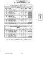
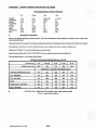
SOFTWARE IDENTIFICATION AND LABELS The software revision for Model 213 will be known as ''Version C" and can be identified by a
lilac (light purple) label on the EPROM on the logic board. All revisions of the dual cup
software will be identified with a LETTER in the third pOSition as compared to 'standard'
software (non dual cup) which will always have a NUMBER in the third position - see example
below. The other digits on the chip label also have specific meanings which are explained In
the chart on the next page.
EXAMPLE-SOFnNARELABELr-______________~
DATECODE
ORDER#
060197060197
36901
00CAL8BC
CHIP#
This software provides a maximum of seven prime selections of which five may feature three
strengths. Selections can include fresh brewed coffee, regular and decaffeinated, chocolate, a
Custom Select Coffee preset for Cafe Mocha - a combination of coffee and chocolate, plus a
minimum of one Soluble Gourmet Coffee (SGC). Fresh brewed tea or soluble tea is also
available in three strengths and each of the selections is available with three levels of
lightener, sugar or sugar substitute. Custom Select Coffee, which offers the operator the
ability to combine a number of ingredients already In the machine to produce a premium drink
such as Cafe Mocha or Balanced Blend™ or an additional SGC are also available as an added
selection. The combinations of drinks available in each machine is determined by the reCipes
present In the particular software for each machine. See MODE 12, page 2.10 for a further
explanation of a reCipe.
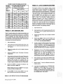
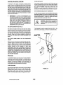
Another change that Increases the flexibility of the AP213 Is the possibility of four different
canister rack configurations. These four canister rack configurations are deSignated by a
number that represents the number of mixIng bowls or troughs, and the number of canisters
in each section, reading the rack from left to right. An example would be a standard canister
rack, from left to right: chocolate, soup, creme, sugar, sugar sub, soluble decaf and tea. This
would be represented as 1-1-5. The chocolate and soup each have their own mixing bowl,
while the balance of the canisters are mixed along with the fresh brewed coffee In a common
mixing channel. See figure below. For the layout of additional canister rack configuration
options, see the Index chart on page 1.01. This will also direct you to the correct configuration
chart, recipes, label aSSignments and canister aSSignments.
1 • 1
Automa1ic Products 213 V1.S 0198
5
1.03
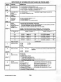
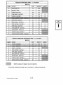
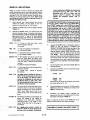
DEFINITIONS OF INFORMA"rlON CONTAINED ON EPROM LABEL,
DIGIT
0
FUNCTION
DESCRIPTION
. CANISTER RACK
CONFIGURATION
0= STANDARD RACK CONFIGURATION 1-1-5
1 = SPLIT TROUGH· SOUP/SGC + 2 SOLUBLE GOURMETS 1-1-2-3
2 = SPLIT TROUGH ~ SOUP/SGC + 1 SOLUBLE GOURMET 1-1-1-4
A = SPLIT TROUGH - 2 SOLUBLE GOURMETS 1-2-4
(digit 1)
0
(digit 2)
C
(See MODE 1, page 3.03 (step 12), 3.04 & 3.05
INDICATES TYPE
OFMIS
INFORMATION THAT IS RECORDED
0= 10 PRICE LINES
5= TOTALS BY PRODUCT BY SIZE SOFTWARE
PROGRAM
VERSION 203 Dual Cup EPROM VERSION 'A' or 'B'
213 EPROM VERSION - 'c' 213 EPROM VERSION - '0' [DISCONTINUED]
DIGIT #4
INDICATES FACTORY SETTING
OF MODE 11, OPTIONS 3 & 5
THIS DIGIT SETS TWO DIFFERENT FUNCTIONS: 1. ON MACHINE SELECTION PANEL, THE #4 SELECTION (4TH ROW DOWN) CAN BE SET
TO EITHER DISPENSE A
OR SGC BEVERAGE. 2. MACHINE CAN OPERATE EITHER ONE OR TWO CUP SIZES.
(digit 3)
A
(digit 4)
.,
esc
LEn~R = 'YES' FOR CUSTOM SELECT COFFEE (CSC) - IN 4TH SELECTION
NUMBER = 'NO' FOR SOLUBLE GOURMET COFFEE (SGC) IN 4.TH SELECrlON
~ IF POSITION 4 IS
,
•
MODE 11, OPTION 3 - ~ .
A
I
I
B-
I
I
01
esc ON
CSCON
I
I
CSC OFF
I
CSCOFF
(setting -+)
(setting -+)
(setting -+)
(setting -+)
Letter 'K' or Higher =
L
8
L=
J=
9=
8=
SMALL CUP SIZE
L= 12 oz
8= B%oz
J= 100z
9= 90z
7= 70z
6= 60z
I
I
2 CUP SIZES (settlng-+)
YES
I
I
1 CUP SIZE
(setting -+)
YES
NO
I
I
2 CUP SIZES (settlng-+)
NO
NO
I
I
1 CUP SIZE
(setting -+)
YES
12 oz
10 oz
90z
B%oz
o =None - one cup size setup using above digit 5 setting for both
,
, .
B= Fresh brew
F= Freeze-dried
X= Disabled ( priced at 99.99 )
Z= Tea replaced with soluble gourmet
(used In Rack Configuration 1 only)
Y=Tea replaced with soluble gourmet & without 3rd SGC programmed
(used In Rack Conflguratlon 1 only)
,
COFFEE
CONFIGURATIONS
A= Grinder
L= All Freeze Dry w/extenslon rack - Cot 1 & 2
B= Grinder & FD Decaf
M= All Freeze Dry w/extenslon ra.ck - Cot 1&2&3
2= Loose Ground (single hopper)
C= Dual Grinder
3= Loose Ground (Single hopper) & FD Decaf
0= Dual Grinder & FD Decaf
4= Dual Hopper (both loose ground)
E= Grinder wlLoose Ground
5= Dual Hopper (both loose ground) & FD Decaf
F= Grinder wlLG & FD Decaf
H= All Freeze-dried w/o extension rack
J= Grinder with FD Decaf .on swln~ut
(digit 8)
-
Automatic Products 213 V1 ,6 0798
NO
7= 7''GIz
6= 60z
TEA
CONFIGURATION
(digit 7)
C
YES
dispensers
(digit 6)
B
MODE 11, OPTION 5 .. ~
CUSTOM CHIP
LARGE CUP SIZE
'digit 5)
I
I
I
1.04
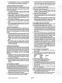
AP 213 INSTALLATION AND SET-UP INSTRUCTIONS INSTALLATION SET·UP INSTRUCTIONS
Unpack the vendor:
1. Remove shipping carton and plastic bag from vendor.
Inspect exterior of cabinet for damage. If damaged, a
shipping damage report should be filed with carrier.
2. CAUTION: THE FOLLOWING PROCEDURE
REQUIRES THAT THE MACHINE HAVE POWER
APPLIED AND APOTENTIAL ELECTRICAl SHOCK
HAZARD EXISTS
Remove clip from lock handle and open front door. If
machine is equipped with a lock, the keys will be in the
cupweli. Inspect cabinet Interior for evidence . of
damage.
Set up the vendor at the locatIon as follows:
1.
. On power panel, set all switches to the OFF positions.
2. Carefully level the vendor using the adjustable leg
levelers
and a level on the top of machine to check from front to
back and side to side.
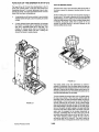
3. If machine is not equipped with a bean grinder, swing
coffee
hopper out and install hopper. Be sure to engage auger
driver with motor drive pin.
4. If machine Is equipped with a bean grinder, swing out
bracket assembly and hopper will be packed separateiy
and placed on the ' floor of the machine. After
unpacking, remove the bottom 3/8" bolt on the bracket
hinge used for the swing outasm. Install the grinder
swing out asm on the hinge bracket and connect the
electrical hamess and replace the bolt. Be sure to
secure the sliding gate (located on the sloped surface
of the bean hopper) in the fully open position to allow
beans into the grinder(s). Install coffee delivery chute to
bottom of swing out bracket and do not tightening wing
nuts yet.
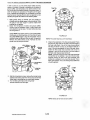
Push swing out asm against brewer until it latches over .
rolier bracket located on brewer asm. Check roller
bracket adjustment to insure swing out bracket holds In
place. Position the bottom opening of the coffee chute
over the center of the brew chamber for best possible
delivery of grounds to brewer then tighten wing nuts .
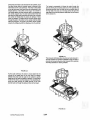
5. On the bottom of water tank asm, make sure the drain
valve is closed. Install water filter cartridge (if so
equipped). On the filter head asm, tum the water lever
on by rotating It clockwise.
6. Remove shipping screw from brewer cam/switch cover.
Locate shipping bolt behind brewer latch & remove
using a 3/8" socket wrench or driver. Remove all
shipping screws from cup dispenser asm.
7. Connect the vendor to the water supply line using 3/8"
0.0. soft copper tubing allowing one complete coli
approximately three feet in diameter between the water
supply line and vendor to allow movement of the vendor
for cleaning and to reduce noise due to water pressure
surges.
3. . Remove cardboard canister rack Insert and all packing
tape from coffee hopper swing out bracket, cup
dispenser door, commodity trough and steam deflector,
overflow and grounds waste bucket floats.
4. Remove all cartons from floor of machine. These
cartons may contain the kick plate, grinder swing out
bracket, coffee or bean hoppers.
LOCATION SITE REQUIREMENTS
This vendor requires an extemal source of water and
electricity for operation. The minimum requirements for these
utilities are asfoliows:
CAUTION; THIS MACHINE IS DESIGNED FOR
INDOOR USAGE ONLY. /4N'( OTHER USAGE MAY VOID
THE MANUFACTURERS WARRANTY.
WATER
The installation site must have a cold drinking water supply line that can be permanently coupled to the vendor. The water supply line should be 1'2 inch minimum diameter and be equipped with a manual shutoff within six feet of the machine. Water pressure should maintain 20 psi minimum while the vendor is taking on water. If water pressure exceeds 90 psi, a pressure regulator should be installed in the line. The . standard plumbing connection shipped with the machine is a 3/8" male flare fitting.
+ INSURE THAT THE WATER SHUT OFF LEVER THAT'S
ON THE INLET WATER FILTER HEAD ASM IN THE
MACHINE IS CLOSED BEFORE HOOK UP OF WATER
SUPPLY (TURN LEVER CCW).
ELECTRICITY
A dedicated grounded electrical outlet rated at 120 volts,
60Hz, single phase and capable of delivering 20 amperes
must be available within six feet of the vendor. Only a
receptacle that contains a right angle neutral should be used
and the H.B.M. should be the only unit in this outlet.
Automatic Products 213 V1 .6 0798 1.05
8. •
9. Plug machine into a 120V, 20A receptacle. Set all
power switches to the ON position. Check that the tank
starts to fill and that there are no leaks. The cup spiral
motor will run for thirty seconds or until the cup present
switches are depressed. The machine Is equipped with
a safety feature· if the Inlet water valve is on for more
than 90 seconds, it will put the machine 'OUT OF
ORDER'. To complete the filling of the heater water
tank, lift and release the bucket switch to reset the 90
second timer. It may be necessary to reset the 90
second timer twice in order to fill tank.
DO NOT GROUND THE PROBE WHILE THE TANK IS
FILLING. THIS WILL SIGNAL THE LOGIC BOARD
THAT THE TANK IS FULL AND THE HEATERS WILL
BE TURNED ON REGARDLESS OF THE LEVEL OF
WATER IN THE TANK.
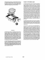
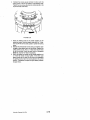
11. Install grounds bucket liner (supplied). Install grounds
bucket behind front flange of rear splash guard. 8e Sure
that the float is Inside the bucket.
12. Install overflow bucket against guide on lower left
comer of machine. Be sure that the float and overflow
hose are inside the bucket.
13. Open cup dispenser doors and load with cups. Cup
dispensers are set to size at the factory according to
original order. If other cups size is desired, refer to
service sect/on for adjustments.
14.
•
Install the coin mech and bill validator, if not already
equipped. Connect all hamesses. See decal on coin
mach enclosure for list of acceptable coin mechanisms.
213 H.B.M.IS CAPABLE OF RUNNING EITHER A 110
OR 24 VOLTS COIN MECH ANDIOR VALIDATOR.
Remove packing tie downs holding the humidity bar.
10. Loosen the two screws holding the brewer grounds
splash guard on the front of brewer. The shield is
designed to be able to swing a littie as the spent
grounds fall against it.
CAUTION: DO NOT USE A 24 VOLT
12 PIN COIN MECH IN THE MACHINE,
ELECTRONIC DAMAGE CAN RESULT.
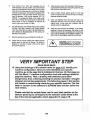
'.VERY IMPORTANT STEP READ READ READ
15. Using the drawings of the canister racks on page 1.07, identify your
machine configuration. Once you have identified your specific
machine, go to the page that is Indicated In that box. On that page you
will find Mode 11 machine configuration chart with settings related to
~ this machine. Next, a drawing with selection panel label
assignments, then a drawing showing the product canisters I troughs I
whippers and wiring assignments. The following pages in that section
will pretain to recipe timing charts for your specifiC machine. The first
letter or number on the software Ie (EPROM) label will also define the
rack version.
Please note that the recipes listed next to each label position on the
selector panel layout correspond to the selection codes listed at the
top of the channel application chart, Appendix IV, page 2.18.
Automatic Products 213 V1 .6 0798 1.06
•
+
FOR STEPS 16 AND 17 BELOW, USE STEP
15 ABOVE TO HELP YOU DETERMINE WHAT
PRODUCTS GOES INTO WHICH CANISTERS/
HOPPERS AND WHERE TO LOCATE THE
PRODUCT LABELS ON THE SELECTION
PANEL.
16. Fill canisters and hoppers with product.
17. Access selector assembly by swinging out cup
dispenser and lowering logic control board. If
the pre-installed condiment or start button labels
need to be replaced, the LED board must be
removed to gain access to slot opening for
labels. Install price labels on selection labels
and insert into appropriate positions. Refer to
the diagram in the rack configuration section to
determine the correct position for each
beverage label (see page 1.09 which will direct
you to your rack layout and label assignments.
REFER TO THE MANUAL OPERATING SECTION
FOR FURTHER INFORMATION ON STEPS 20
'rHROUGH 22 BELOW.
20. Access MODE 11 using the security key on the
inside of the door and check that the
configuration and options are set correctly for
the machine. Proceed to MODE 13 & set
payment options. If discount mode is being
used, selections being discounted must be
assigned in MODE 14.
+
+
+
ALL INGREDIENT SETTINGS TIMES ARE
MADE FOR THE LARGE DRINK. THE
FACTORY SETTINGS FOR THE DRINK SIZES
CAN BE DETERMINED BY CHECKING THE
LABEL ON THE SOFTWARE. SEE CHART,
PAGE 1.03
23. After completing the product adjustments, install
the commodity chutes. Install the humidity bar
(heater) on the canister rack so that the tabs on
the humidity bar fit into their respective slots
between the canisters. Connect the humidity bar
harness to the machine harness (located to the
left of the chocolate canister).
25. Test all selections and additives using cash
credit with coins and bills.
The correct function of the security key switch
is: ON then OFF - the key" should ~ be in
the position where key can be-removed.
SETTING PRICES TO 0.00 WILL SET A
SELECTION TO FREE VEND.
SETTING A PRICE TO 99.99 WILL DISABLE
A SELECTION AND CAUSE THE MESSAGE
"MAKE ANOTHER SELECTION" TO APPEA~
WHEN THE SELECTION IS
PRESSED. THIS IS USEFUL FOR BLOCKING
UNUSED
SELECTIONS OR DISABLING A SELECTION
WHEN IT IS OUT OF ORDER.
Automatic Products 213 V1.6 0798 22. Adjust commodities for the correct throw for the
large drink only by accessing MODE 12 (see
page 2.10). After confirming that the times for
liquids are correct, cup levels should be
adjusted using flow restrictor on each
commodity valve except for the brew water
valve which must be adjusted In the program ..
24. Install chocolate whipper mixing bowl cover.
21. Set selection prices by accessing MODE 4 & 5
and assigning prices to selections. Mild and
regular strength beverages are automatically
assigned the same price while each strong
beverage may be assigned a different price.
+
BOTH ·MODE 4 AND 5 MUST BE SeT FOR
THE LARGE AND REGULAR DRINKS TO
VEND CORRECTL Y.
1.0SA
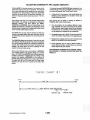
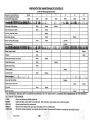
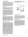
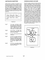
ADJUSTING COMMODITY AND LIQUID AMOUNTS It is important to press STARTIENTER after changing anyone
of these settings and retumlng to MODE 12 to ensure that all
new values are entered. See Timing Chart #1 below.
Entering MODE 12 provides access to the channels which
control the dispense times of all Ingredients. The dispense
time of each commodity and It's sequence In the vend cycle Is
controlled by the microprocessor. Precise time adjustments
determine the exact amount of Ingredients dispensed. This
exact time sequence ability enables accuracy to 1/100 of a .
second.
•
Each channel may have up to three separate settings within
each channel. The settings are accessed by pressing the
start/enter selection. The three settings are START,
DURATION and MODIFIER. Each of these settings can be
adjusted by Increalling or decreasing the digits shown on the
scrolling display by preSSing the Increase digit (coffee strong)
or the next digit (cOffee regular) buttons.
THROUGHOUT THIS MANUAL THE WORD START OR
ENTER ALWAYS REFERS TO THE RIGHT HAND OR
LARGE START BUTTON.
Each channel can be tested by pressing the MODE 12
CHANNEL TEST switch (middle sugar).
The START time of each channel Indicates the time each
function or commodity begins within each vend cycle. All times
are permanently stored to guarantee the correct sequence of
.operation.
The DURAnON determines the length of time within the vend
cycle that each channel will operate. The amount of Ingredient
for a medium strength selection Is controlled by adjusting the
duration. After confirming that the duration for liquids are set .
correctly, cup levels should be set by adjusting the flow
restrlctor on the commodity valves.
•
Once the dUrations for the additives (lightener, sugar,
sugar substitute) have been set correctly for the brewed
coffee channels, these duration times can be duplicated
and entered Into the channels for freeze-dried products
and tea selections to simplify the set up procedul8.
,
All Ingredient throws set In MODE 12 al8 the actual throw
used for the middle or regular button on the lB~B size cup
,
Standard times, settings and prices can be I810aded using
MODE 16. See MODE 16 for mOl8 information.
,
Certain channels may be used In diffel8nt I8cipes to
control diffel8nt functions. Confirm that you are using the
correct I8clpe list for your machine. .
FOR ADDmONAL INFORMATION ON CHANNEL USAGE·
SEE APPENDIX IV • CHANNEL APPLiCATION CHART ON
PAGE 2.18
Some product channels have a third setting· a MODIFIER.
This modifier appears In the scrolling display as a number
below 1.00 (100%). The MODIFIER value Is the percentage of
Increase or decrease In Ingredient throw tor a strong or mild
selection. For example, a MODIFIER of .25 on channel 15
(brewed ooffee.;sugar) means that for an extra sugar selection
the sugar motor will run 25% longer and tor a lesser sugar
selection, the motor will run for a period of lime that is 25%
shorter.
TIMING CHART
#1
START
FINISH
VEND TIME
SUGAR S1ART
MODIFIER LESS
Automatic Products 213 V1 .6 0798
1.068
MODIFIER MORE
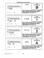
CANISTER RACK INDEX CHART ~~P
-
1 - 1
f(J
SEE CONFIGURATION CHART, CANISTER
RACK LAYOUT, RECIPES AND LABEL
ASSIGNMENTS ON PAGE 1.08
5
RACK
CONFIGURATION
§ ,~:P
r:·:~j;::::~
1 -1
-
2
-
3
~~~
1 - 1 - 1.
· 4
1-1-2-3
-
Automatic Products 213 V1.6 0798
4
1
SEE CONFIGURATION CHART, CANISTER
RACK LAYOUT, RECIPES AND LABEL
ASSIGNMENTS ON PAGE 1.14
RACK
CONFIGURATION
1-1-1- 4
2
. SEE CONFIGURATION CHART, CANISTER
RACK LAYOUT, RECIPES AND LABEL
ASSIGNMENTS ON PAGE 1.25
RACK
CONFIGURATION
~~-Y
1 - 2
RACK
CONFIGURATION
1-1-5
1-2-4
,
A
SEE CONFIGURATION CHART, CANISTER
RACK LAYOUT, RECIPES AND LABEL
ASSIGNMENTS ON PAGE 1.20
1.07
RACK
~ONFIGURAnON
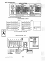
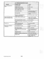
RACK CONFIGURATION 0
o
for large drink if aut of IlI'g'
OPT 7 YIN No lubltitutian if out of large cups, will displ.y
'USE OTHER CUP SIZE'
is n..d,d .
o
OPTION 1 MUST BE YES TO HAVE FRESH BREWED DECAF
SELECTOR. PANEL LAYOUT
RECIPE'
R'2uler Coif..
0
0
0
81B/91F
DlClf Coft..
0
0
0
82B/82F
C.fe Mach.
0
B.I.nced Blend
0
QI 0
0 I0
0 I0
0
Til
83B/83F
84/84B/84F
est
I
I
I
I
I
RECIPE I
!:!ihtenll'
0
0
0
Suaer
0
0
0
SUI_ Sub
0
0
0
SGC 11/SOUP
.Chacol.t.
0
8S
0
87
START
0
ClncelO
0
t FB & FO TEA USE THE SAME CHANNELS· SEE RECIPES
1-1-5
RACK LAYOUT lac
bl
. A2
C
S
H
G
C
1
0
C
1\3
A4
L
I
T
E
A so; 180rpm motor
B = 9Drpm motor
C - 51rpm motor
V= Valve
W= Whipper
Automatic Productl 213 V1 .3 0994 C5
$.
(!
B
C6
W1RIN6 ASSIGNMENTS
c711~
Valves
-1...cwv
2=S'YIV
J=TWV Molors 1\1- CHOC A2=- SOUP T
E
A
A3=:SUG . A~LlT
·C!PoLCS
(L:I\J Grinder
LG 1.08
C6-FDD
C7""TEA
I'!IJ!I!I!~'!'!'. i'!'!'H'!'!'Gt!'!'".!'!'!; i!'P!ti"!'!d'!'!'~'!'!'It~
...... ...... . [G: ::: :::: ::::::
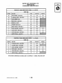
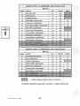
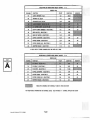
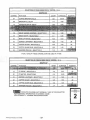
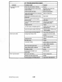
RECIPE LIST FOR MODEL 213
VERSION OOC
STANDARD CANISTER RACK
SELECTION #1 FRESH BREW
CHANNEL
FUNCTION
05
LARGE GRINDER . SELECTION 1
06
LG REGULAR COfFEE· SELEC
07
COFFEE BREWER CYCLE
08
BREW WATER· SELECTION 1
09
BREWER FILL DELAY
RACK
CONFIGURATION
,.,,6
fZJ
COFFEE· 12 oz. REGULAR
START
DURATION
MODIFIER
0.3
1.30
.25
10
11
12
COFFEE LIGHTENER· SELECTION 1
13
COFFEE SUGAR· SELECTION 1
14
COFFEE SUGAR SUB· SELECTION l '
15
WHIPPER·TROUGH . SELECTION 1
SELECTION
FUNCTION
13
4
15
COFFEE· 12 oz. REGULAR
START
DURATION
MODIFIER
COFFEE SUGAR· SElECTION 1
COFFEE SUGAR SUB· SELECTION 1
WHIPPER·TROUGH . SELECTION 1
FOR ADDITIONAL INFORMATION ON CHANNEL USAGE· SEE APPENDIX IV • CHANNEL APPLICATION CHART
AUlomllic PrOducts 213 V1.2 0898
1.09
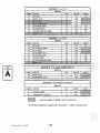
RACK
CONFIGURATlON
o
oz.
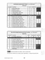
RECIPE 82B
CHANNEL
FUNCTION
07
COFFEE BREWER CYCLE
09
BREWER
START
DURATION
4.0
25.00
5.1
5.80
0.00
1.05
12.5
12.5
11.3
# ONLY ONE OF THESE CHANNELS MAY BE USED AT A TIME
. 12oz.
20
FD WATER· SELECTION 2
21
COFFEE LIGHTENER· SELECTION 2
22
COFFEE SUGAR - SELECTION 2
3.8
1.60
23
COFFEE SUGAR SUB· SELECTION 2
3.8
1.40
24
WHIPPER·TROUGH .
1.9
00.0
0.8
2
10.60
1.05
INDICATES CHANNELS NOT NORMALLY USED IN THIS SELECTION
FOR ADDITIONAL INFORMATION ON CHANNEL USAGE · SEE APPENDIX IV· CHANNEL APPLICATION CHART
Automotlc Producu 213 V 1 .2 0898
1.10
SELECTION 113. CUSTOM SELECT COFFEE . 12
RACK CAFE MOCHA
Ill.
CONFIGURATION RECIPE g3B
CHANNEl
START
DURATION
29
MAKE·UP WATER· SELECTION
12.3
0.00
30
COFFEE LIGHTENER • SELECTION 3
10.6
0.60
10.9
1.12
10.9
1.10
9.6
B.OO
16.0
2.30
31
32
3
COFFEE SU
33
34
CHOCOLATE AUGER· SELECTION 3
35
CHOCOLATE WATER & WHIPPER·
"
3.55
. 12
SELECTION 13 FREEZE DRIED
Ol.
CAFE M CHA
RECIPE e3F
CHANNEL
FUNCTION
START
DURATION
MODIFIER
30
31
32
33
34
11.0
35
10.0
3.55
INDICATES CHANNELS NOT NORMALLY USED IN THIS SELECTION
FOR ADDITIONAL INFORMATION ON CHANNEL USAGE· SEE APPENDIX IV· CHANNEL APPLICATION CHART
Automatic ProduclO 213 V1.2 0686
1.11
RACK CONFIGURATION SELECTION #4 FB CSC . 12 oz. BALANCED
· J
ND . SlEND OF REGULAR AND
RECIPE
"
1.00
5.30
43
13.0
0.00
44
12.0
1.05
45
12.5
1.60
46
12.5
1.40
40
43
1.80
FD WATER· SElECTION 4/CSC
0.8
10.60
2.5
1.05
3.5
1.60
.25
INDICATES CHANNELS NOT NORMALLY USED IN THIS SElECTION
FOR ADDITIONAL INFORMATION ON CHANNEL USAGE· SEE APPENDIX lV . CHANNEL APPLICATION CHART
Automatic Produc:ta 213 V1 .2 0696
1.12
RACK
~ONFIGURAnON
"
SELECTION #7 . 12
CHANNEL
67
. 68
FUNCTION
START
DURATION
AUGER
2.2
6.60
WATER/WHIPPER· CHOCOLATE
1.0
10.50
CH
INDICATES CHANNELS NOT NORMALLY USED IN THIS SELECTION
INFORMATION ON CHANNEL USAGE· SEE APPENDIX IV • CHANNEL APPLICATION CHART
Automatic Products 213 V1.2 0696
1.13
RACK CONFIGURATION 1
MODE 11 OPTIONS
No substitution if out of IIrg. cups. will display
"USE OTHER CUP SIZE"
OPT 7 YIN
RACK
CONFIGURATION
• OPTION 1 MUST BE YES TO HAVE FRESH BREWED DECAF
1-1-2·3
1
SELECTOR PANEL LAYOUT
RECIPE'
RECIPE'
Regular Coff..
D.Clf Coff••
c.1e Mach.
SGC 12 OR CSC 12
SGC II
a
a
a
a
a
a
a
a
a
a
a
a
a
a
a
RACK LAYOUT 18C
11B/m
I
Ughten.
12B/12F
I
Sug.
13B/13F
[
Sugar Sub
14/14B/14F
I
I
15
SOUP
CHOCOLATE
a a a
a a a
a a a
a
a
18
START
a a
CanCiI
17
1-1-2-3
\IIIRING ASSIGNMENTS
Valves - 1-cvN
2= BT\IIV
A2
AJ
A4
3- S'YIV
4= T\IIV
A5
WotO($ A1= CHOC
C
H
A2- SOUP
A3= TEA
o
A4- FDG
AS: SUG
C
AI)::
LIT
r:7- LCS ..
A = 111lrpm motor
B = 90rpm motor
C = 51rpm motor
V- Valve
W= Whipper
Automatic Producte 213 V1.3 0994
....................
.................... 1.14
roo
a
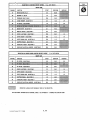
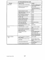
RECIPE LIST FOR MODEL 213 VERSION 10C SPLIT TROUGH CANISTER RACK 1-1-2-3 REGULAR
SELECTION #1 FRESH BREW REGULAR COFFEE .·
RECIPE 11B
CHANNEL
05
FUNCTION
GRINDER· SELECTION 1
START
DURATION
MODIFIER
0.3
1.30
.26
.25
06
lG REGULAR COFFEE • SELECTION 1
0.2
2.50
07
COFFEE BREWER CYCLE
4.0
26.00
09
BREW WATER· SELECTION 1
5.1
5.90
09
BREWER FILL DELAY
7.4
3.60
10
PRESSURE RELIEF DELAY
19.0
2.50
11
MAKE·UP WATER· SELECTION 1
12.0
0.00
12
COFFEE UGHTENER . SELECTION 1
12.5
1.05
13
COFFEE SUGAR . SELECTION 1
12.5
1.60
14
COFFEE SUGAR SUB· SELECTION 1
12.0
1.40
15
WHIPPER·TROUGH . SELECTION 1
9.6
0.0
RACK
CONFIGURATION
1·1·2·3
. 12
SELECTION #1 FREEZE DRIED REGULAR
OZ.
1
REGULAR
RECIPE 11F
CHANNEL
FUNCTION
START
DURATION
MODIFIER
.25
06
FD REGULAR COFFEE • SElECTION 1
2.9
3.70
11
FD COFFEE WATER· SELECTION 1
0.9
10.60
12
COFFEE LIGHTENER· SElECTION 1
2.2
1.05
13
COFFEE SUGAR· SELECTION 1
3.8
1.60
14
COFFEE SUGAR SUB • SELECTION 1
3.9
1.40
15
WHIPPER·TROUGH . SELECTION 1
1.9
0.0
FOR ADDITIONAL INFORMATION ON CHANNEL USAGE· SEE APPENDIX IV . CHANNEL APPLICATION CHART
Automatic Producu 213 V1.2 0898
1.15
SELECTION #2 FRESH BREW DECAF COffEE : 12 oz.
12B
CHANNEL
START
FUNCTION
DURATION
07
COFFEE BREWER CYCLE
4.0
09
BREWER FILL DELAY
7.4
19
BREW WATER· SELECTION 2
5.1
5.80
20
MAKE UP WATER· SELECTION 2
13.0
0.00
21
COFFEE LIGHTENER· SELECTION 2
12.0
1.05
22
COFFEE SUGAR· SELECTION 2
12.5
1.60
23
COFFEE SUGAR SUB· SELECTION 2
12.5
1.40
24
WHIPPER·TROUGH • SELECTION 2
11 .3
0.0
MODIFIER
18
RACK
CONFIGURAliON
'·'·2·3
·1 # ONLY ONE OF THESE CHANNELS MAY BE USED ATA TIME
SELECTION #2 FREEZE DRIED DECAF COffEE· 12 oz.
20
O.B
10.60
21
COFFEE LIGHTENER ' .SELECTION 2
2.2
1.05
22
COFFEE SUGAR· SELECTION 2
3.B
1.60
23
COFFEE SUGAR SUB· SELECTION 2
3.B
1.40
24
WHIPPER·TROUGH • SELECTION 2
1.9
0.0
INDICATES CHANNELS NOT NORMALLY USED IN THIS SELECTION
FOR ADDITIONAL INFORMATION ON CHANNEL USAGE· SEE APPENDIX IV . CHANNEL APPLICATION CHART
Automatic Products 213 VI .2 0696
1.16
SELECTION #3 CUSTOM SELECT COFFEE • 12
OL
CAFE MOCHA
RECIPE 138
CHANNel
FUNCTION
START
OURATION
07
BREW MOTOR CYCLE
4.0
25.00
09
BREWER FILL DELAY
7.4
3.60
10
PRESSURE RELIEF DELAY
19.0
2.50
25
LARGE GRINDER· SELECTION 3
0.3
1.00
29
MAKE·UP WATER· SELECTION 3
12.3
0.00
30
COFFEE LIGHTENER· SELECTION 3
10.6
0.65
31
COFFEE
11 .0
1.10
32
COFFEE SUGAR SUB· SELECTION 3
11.0
1.00
33
WHIPPER·TROUGH • SELECTION 3
9.6
B.OO
34
CHOCOLATE AUGER · SELECTION 3
16.0
2.30
35
CHOCOLATE WATER & WHIPPER · SELECTlDN 3
15.0
3.55
• SELECTION 3
RACK
CONFIGURATION
1·1·2·3
1
SELECTION #3 FREEZE DRIED CUSTOM SELECT COFFEE . 12 oz. CAFE MOCHA
RECIPE 13F
CHANNEL
FUNCTION
START
DURATION
30
COFFEE 'LIGHTENER· SELECTION 3
2.2
0.65
31
COFFEE
3.3
1.12
32
COFFEE SUGAR SUB . SELECTION 3
3.3
1.10
33
WHIPPER·TROUGH • SELECTION 3
1.9
6.80
34
CHOCOLATE AUGER · SELECTION 3
11.0
2.30
35
CHOCOLATE WATER & WHIPPER · SELECTION 3.
0.0
3.55
• SELECTION 3
MODIFIER
INDICATES CHANNELS NOT NORMALLY USED IN THIS SELECTION
FOR ADDITIONAL INFORMATION ON CHANNEL USAGE· SEE APPENDIX IV . CHANNEL APPLICATION CHART
Automatic Product1l 213 V1 .2 0696
1.17
SELECTION #4 FB CSC . 12
DZ.
BALANCED BLEND·
RECIPE 14B
CHANNEL
RACK
CONFIGURATION
1
START
DURATION
07
BREW MOTOR CYCLE
4.0
25.00
09
BREWER FILL DELAY
7.4
3.60
10
PRESSURE RELIEF DELAY
19.0
2.50
38
LARGE GRINDER· SELECTION 4/CSC
0.3
1.00
.25
39
COFFEE AUGER· SELECTION 4/CSC
1.4
1.25
.25
40
DECAF (LG/SMALL GRINDER) . SELECTION 4/CSC
0.2
1.00
.25
42
BREW WATER· SELECTION 4/CSC
5.1
5.30
13.0
0.00
43
1-1-2-3
FUNCTION
.MAKE·UP WATER· SELECTION 4/CSC
44
COFFEE LIGHTENER· SELECTION 4/CSC
12.0
1.05
.30
45
COFFEE SUGAR· SELECTION 4/CSC
12.5
1.60
.30
46
COFFEE SUGAR SUB·
12.5
1.40
.25
4/CSC
SELECTION #4 FD CSC . 12 oz. BALANCED BLEND· BLEND OF REGULAR AND DECAF
RECIPE 14F
CHANNEL
FUNCTION
START
DURATION
MODIFIER
39
COFFEE AUGER: SELECTION 4/CSC
5.0
1.80
.25
40
DECAF· SELECTION 4/CSC
2.3
1.80
.25
43
FDWATER • SELECTION 4/CSC
0.8
10.60
44
COFFEE LIGHTENER· SELECTION
2.2
1.05
45
COFFEE SUGAR· SELECTION 4/CSC
3.8
1.60
46
COFFEE SUGAR SUB · SELECTION 4/CSC
3.8
1.40
INDICATES CHANNELS NOT NORMALLY USED IN THIS SELECTION
FOR ADDITIONAL INFORMATION ON CHANNEL USAGE· SEE APPENDIX IV . CHANNEL APPLICATION CHART
Automatic Product. 213 V1.2 0696
1.18
RACK
CONFIGURATION
1-1-2·3
1
SELECTION #7 • 12 OZ. WHIPPED HOT CHOCOLATE
RECIPE 17
CHANNEL
FUNCTION
START
DURATION
67
CHOCOLATE AUGER
2.2
6.50
68
WATER/WHIPPER· CHOCOLATE
1.0
10.50
INDICATES CHANNELS NOT NORMALLY USED IN THIS SELECTION
FOR ADDITIONAL INFORMATION ON CHANNEL USAGE· SEE APPENDIX IV . CHANNEL APPLICATION CHART
.1
Automatic Producu 213 Vl .2 0896
1.19
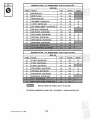
RACK CONFIGURATION A RACK LAYOUT AC3C 1-2-4 WIRING ASSIGNMENTS
IAI
A2
A3
A4
AS
Valves - 1-CWV
2=SWtI
3""TWtI
C6
NotorsAl; (HOC
C
H
A2= SOUP
A3- FDG
0
A4... SUG
C
A5= LIT
CG- LCS
C1=TEA
A= 180rpm motor
B - 90rpm motor
C;;;; 51rpm motor
V= Valve
W- Whipper
Aut.mlti. P,.ducta 213 V1.3 0994
Grinder
LG
1.20
Mini:Giinihi
t.tt ~ ~~~~~~~~~~~~
....
.................
.. ... ...... ......
01
01
FDD
FDD
RECIPE LIST FOR MODEL 213 VERSION AOC SPLIT TROUGH CANISTER RACK 1-2-4 SELECTION #1 FRESH BREW REGULAR COFFEE · 12
REGULAR
RECIPE A1B
NEL
FUNCTION
START
DURATION
MODIFIER
05
LARGE GRINDER • SELECTION 1
0.3
1.30
.25
06
LG REGULAR COFFEE · SELECTION 1
0.1
2.50
.25
07
COFFEE BREWER CYCLE
4.0
25.00
08
BREW WATER· SELECTION 1
5.1
5.80
09
BREWER FILL DELAY
7.4
3.60
10
PRESSURE RELIEF DELAY
19.0
2.50
11
MAKE·UP WATER· SElECTION 1
13.1
0.00
12
COFFEE LIGHTENER· SElECTION 1
12.0
1.05
.30
13
COFFEE .SUGAR . SELECTION 1
12.5
1.BO
.30
14
COFFEE SUGAR SUB • SELECTION 1
12.5
1.40
.25
15
WHIPPER·TROUGH . SELECTION 1
8.B
0.0
.#1 FREEZE DRIED REGULAR COFFEE .· 12 oz. REGULAR
RECIPE A1F
CHANNel
FUNCTION
START
06
FD REGULAR .COFFEE· SELECTION 1
2.8
11
FD COFFEE WATER · SELECTION 1
0.8
12
COFFEE LIGHTENER· SElECTION 1
2.2
13
COFFEE SUGAR· SELECTION 1
3.8
14
COFFEE SUGAR SUB . SELECTION 1
3.8
15
WHIPPER·TROUGH • SELECTION 1
1.9
DURATION
MODIFIER
FOR ADDITIONAL INFORMATION ON CHANNEL USAGE· SEE APPENDIX IV • CHANNEL APPLICATION CHART
Automatic Proclucta 213 V1 .2 0898
1.21
RACK
CONFIGURATION
. 1-2-4
A
SELECTION #2 FRESH BREW DECAF COFFEE· 12 oz. RECIPE A2B CHANNEL
FUNCTION
START
DURATION
07
COFFEE BREWER CYCLE
4.0
25.00
09
BREWER FILL DELAY
7.4
3.60
19
BREW WATER·
20
MAKE UP WATER· SELECTION 2
13.0
21
COFFEE LIGHTENER • SELECTION 2
12.0
1.05
22
COFFEE SUGAR· SELECTION 2
12.5
1.60
23
COFFEE SUGAR SUB • SElECTION 2
12.5
1.40
24
WHIPPER·TROUGH· SELECTION 2
11.3
0.0
2
5.1
# ONLY ONE OF THESE CHANNELS MAY BE USED AT A TIME
SELECTION #2 FREEZE DRIED DECAF
~
12 oz.
. RACK
CONFIGURATION
1-24
A
20
FO WATER· SELECTION 2
0.8
10.60
21
COFFEE LIGHTENER· SELECTION 2
2.2
1.05
22
COFFEE SUGAR • SELECTION 2
3.8
1.60
23
COFFEE SUGAR SUB· SELECTION 2
3.8
1.05
24
WHIPPfR·TROUGH • SElECTION 2
1.9
0.0
INDICATES CHANNELS NOT NORMALLY USED IN THIS SELECTION
FOR ADDITIONAL INFORMATION ON CHANNEL USAGE· SEE APPENDIX IV . CHANNEL APPLICATION CHART
"'utomltlc ProduC18 213 V1.2 08S8
1.22
. . ... -... .
__ .. . . . . - .. . ..... ._-
---
SELECTION #3 CUSTOM SELECT COFFEE . 12 oz. CAFE MOCHA RECIPE A3B CHANNEL
FUNCTION
START
DURATION
07
BREW MOTOR CYCLE
4..Q
25.00
09
BREWER FILL DELAY
7.4
3.60
10
PRESSURE RELIEF DELAY
19.0
2.50
25
LARGE GRINDER · SELECTION 3
0.3
1.00
INDICATES CHANNElS NOT NORMALLY USED IN THIS SELECTION
FOR ADDITIONAL INFORMATION ON CHANNEL USAGE· SEE APPENDIX IV • CHANNEL APPLICATION CHART
Automatic Product. 213 Vl .2 0696
, .23
RACK
CONfiGURATION
1-24
A
SELECTION #7 . 12
oz. WHIPPED HOT CHOCOLATE
RECIPE A7
CHANNel
FUNCTION
START
DURATION
67
CHOCOLATE AUGER
2.1
6.60
68
WATER/WHIPPER · CHOCOLATE
1.0
10.50
INDICATES CHANNELS NOT NORMALLY USED IN THIS SELECTION
FOR ADDITIONAL INFORMATION ON CHANNEL USAGE· SEE APPENDIX IV . CHANNEL APPLICATION CHART
Automatic Producu 213 Y1·.2 0696
1.24
RACK CONFIGURATION 2
MODE 11 OPTIONS
OPT 7 YIN
drink for large drink if out of large cups
is needed
• OPTION 1 MUST BE YES TO HAVE FRESH BREWED DECAF
SELECTOR PANEL LAYOUT
I
RECIPE"
RECIPE"
Regular Coffee
0
0
o
Decaf Coffee
0
0
0
Cafe Mocha
0
0
FD Gunnet 1 Tea
0
0
I 22B/22F
0 I 23B/23F
o I 24
SGC#2
0
Q
o
21B/21F
J25t
IQ
0
Sugar
1010
0
Sugar Sub
1010
0
0
Liahtener
SGC #11 Soup
0
26
CHOCOLATE
0
27
START
00
Cancel
0
:): FB & FD TEAUSE SAME CHANNELS SEE RECIPE TABLE
RACK LAYOUT 20C
1-1-1-4
HOT
A2
A3
A4
A5
C6
WATER
TANK
5
Valves: 1- CWS
2- BTWV
3- SOUP
4-TWV
5- BCV
Motora: A 1 • CHOC
A2. TEA
A3. SOUP
A4. SUG
AS. LIT
ce. LCS or
FDD or FOG
C7. LCS or
FOD or FOG
W1
W2
i i i L._._._._._._._-_.
~-----,
=180 RPM MOTOR ,..- - - , (DeCAF or\ C =51 RPM MOTOR I FOG Dr I Grinder
V =VALVE _ WATER ~ TEA Dr
:
LG
SUB
W = WHIPPER MOTORl. ..... _--, ,/
A
B
= 90 RPM MOTOR
Automatic Products 213 V1.6 0798
1.25
(Mini Grinder \
: Loose Grind :
\
....
_-------,,
RACK
CONFIGURATION
1-1-1-3
2
~1E(ciPE l~Sl'
[FOR MODEL 2 ~ 3l VERSION ;zoe OR 25<C slPur lROUGH CAN!STER RA<C&{ 1=1 =1 a31 ·12 oz. REGUUlIR
#1 FRESH BREW REGULAR
SE
RECIPE 218
CTION
START
DURATION
MODIFIER
0.0
1.30
.25
05
UlIRGE
06
LG REGULAR COFFEE· SELECTION 1
0.0
07
COFFEE BREWER CYCLE
4.0
08
BREW WATER· SELECTION 1
5.1
09
BREWER FILL DEUlIY
7.4
10
PRESSURE RE
19.0
MAKE-UP WATER - SELECTION 1
13.1
ECTION 1
1
SELECTION #1 FREEZE DRIED REGULAR COFFEE - 12 oz.
DURATION
CHANNEL
MODIFIER
06
2.2
RACK
CONFIGURATION
1-1-1-3
2
13
COFFEE
14
COFFEE SUGAR SUB
15
WHIPPER-TROUGH
.
3.8
- SELECTION 1
3.8
1
1.9
INDICATC:S CHANNELS NOT NORMALLY USED IN THIS SELECTION
FOR ADDITIONAL INFORMATION ON CHANNEL USAGE - SEE APPENDIX IV - CHANNEL APPLICATION CHART
Automatic: Products 213 V1.6 0798
SlEllECTION
~
fRESH BREW DECAF
RECIPE 228
FFEE BREWER CYCLE
START
DURATION
4.0
25.00
7.4
3.60
19
5.1
20
13.0
21
COFFEE LIGHTENER - SELECT
22
COFFEE
12.0
2.5
- SELECTION 2
2
12.5
11.3
UGH - SELECTION 2
$$ ONLY ONE OF THESE CHANNELS MAY BE USED AT A TIME
CTiON #2 FREEZE DRIED DECAF CO
RECIPE 22F
18
2.8
20
0
10.60
21
2.2
1.05
22
3.8
1.60
3.8
1.05
1.9
0.0
3
24
COFFEE SUGAR
2
WHIPPER·TROUGH
INDICATES CHANNELS NOT NORMALLY USED IN THIS SELECT!ON
ONAl INFORMATION ON CHANNEL USAGE·
FOR
SEE APPENDIX IV - CHANNEL APPLICATION CHART
Automc:tic Products 213 V1 .6 0798
~ .21
RACK
CONFIGURATION
1-1-1-3
2
SlEllElC1riO~
#lICIUSrOM SELECT COFfEIE - 12 oz . CAFE MOCHA
RIEC!PE 2318
FUNCTION
START
07
BREW MOTOR CYCLE .
4.0
09
BREWER FILL DELAY
7.4
31
10.9
COFFEE SUGAR SUB - SELECTION 3
32
. WHIPPER-TROUGH - SELECTION 3
33
9.6
8.00
34
CHOCOLATE AUGER - SELECTION 3
16.0
2.30
35
CHOCOLATE WATER & WHIPP
15.0
3.55
- SEL - 3.
r-.-.,"'....... - 12 oz. CAFE s
START
29
0.8
6.80
30
2.8
.65
31
2.8
1.12
2.8
1.12
2.5
8.00
11 .0
2.30
10.0
3.55
32
FD WATER - SELECTION 3
COFFEE S
33
UGH - SELECTION 3 -
34
35
AUGER - SELECTION 3
CHOCOLATE WATER & WHIPPER
SELECTION 3
INDICATES CHANNELS NOT NORMALLY USED IN THIS SELECTION
FOR ADDITIONAL INFORMATION ON CHANNEL USAGE - SEE APPENDIX !V - CHANNEL APPLICATION CHART
Automatic Products 213 V1 .6 0798
41.2~
- 12 oz. SOLUBLE
START
CHANNEL
2.8
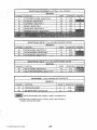
SELECTION #5
CHANNEL
FUNCTION
SELECTION #6· SGC #1 ·12 oz. SOLUBLE GOURMET COFFEE
RECIPE 26
CHANNEL
65
66
FUNCTION
SGC #1 AUGER - SELECTION 6
SGC #1 WATERJWHIPPER - SELECTION 6
DURATION
2.0
6.15
c~~~t"~':l~'"
10.20
'.~?F~~~~
1.0
SELECTION #7 -12 OZ. WHIPPED HOT CHO
RECIPE 27
FUNCTION
CHANNEL
67
CHOC
68
WATERIWHIPPER - CHOCOLATE
AUGER
START
DURATION
2.1
6.60
1.0
10.50
~
INDICATES CHANNELS NOT NORMALLY USEQ IN Tf"!lS SELECTION
FOR ADDITIONAL INFORMATION ON CHANNEL USAGE - SEE APPENDIX IV
- CHANNEL APPLICATION CHART
Automatic Products 213 Vl.6 0798
MODIFIER
.. ..
START
213 ELECTRONICS CONTROL SYSTEM
INTRODUCTION
There are 1B modes in which the control · system can
operate. The various modes are used to access the
accountability data, set up the machine and perform service
diagnostics.
Mode 0 . The normal operating mode of the machine
during which a user may establish oredit and select a
drink.
Upload RS232C. Allows uploading of
machine program from a programming
device to the machine control board.
Mode 10:
Download RS232C. Allows the
downloading of the machine program
from
the control board to a
programming device.
SECURITY KEY REQUIRED:
Mod.. 1 . 10 . Service modes acoessible by
operation of the "mode" switch inside the machine.
This switch Is aocesslble once the door Is opened i.e.
only the door key is required.
Mode. 11 - 17 - Additional service modes accessible
only if a key for the security switch is used. All
security keys are identical.
DESCRIPTION OF MODES
Mode 0: Mode 9:
Mode 11:
Machine configuration. Allows
definition of machine type and options.
Also controls default functions of the
dual cup when one oup is sold out.
Mode 12:
Set ingredient channel times. Used to
set start and duration times and
strength modifiers.
Mode 13:
Set Options. Used to set payment and
volume options .
Mode 14:
Set discount bits. Used to indicate
which selections may be discounted.
Operate mode . Normal operating mode.
Door key required:
Mode 1: Display report. Displays accountability
information.
Mode 15:
Not used
machine.
Mode 2 : Test vend. Allows
without credit.
test vend
Mode 16:
Load standard times and prices. Used
to load factory standard time settings.
Mode 3: Manual flush cycle. Used to flush the
mixing ohannels and bowls with water.
Mode 17:
Smart display user message. Used to
program the scrolling message using
the machine selector panel.
Mode 4:
Set large drink prices.
set/check the prices of
selections.
Mode 5: Set regular drink prices. Used to
set/check the prices of all regular size
selections.
Mode 6: Diagnostics. Checks all segments of the
scrolling display, all indicator lamps and
lists closed logic level switohes.
Mode 7: Channel timed test. Selected channel is
turned on fo.r the normal vend duration
time.
Mode 8: Channel continuous test. Selected
channel is manually turned on until is
manually turned off again .
Automatic Producta 213 V1 . 1 C394 one
Used to
all large
2.01
on
the
213
hot drink
MOVE FLASHING
DIGIT
INCREASE FLASHING DIGIT
-.0:>
(
11.1Ohte"."..
[ Sugar
[ Sugar 5La>
I
SoIoA)/ s::;c
[ Choc;
c:>
0)
OO[QJ1
000
I~_"")'
S4IIf4C1. 0-1"'-:
"1~ It4dl'tlv_
...
--.~
0001
OJ
Strt
,. . .
n
a a qO
"-Out....
L~
~
SNTER
S.10 PAY'OLJT
5 . 25 PAYOUT
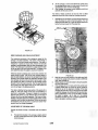
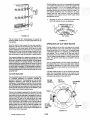
USE OF KEYBOARD
ENTER
Throughout this service manual, the
word ENTER always refers to the large
START (right hand) selection switch.
When in any of the service modes the selection panel
switches perform different functions. A diagram showing
the function of the switches is shown above.
COIN DISPENSE
SPECIAL BUTTONS
At any time, in any service mode, the three switches for
decaffeinated coffee (selection 121 can be used to dispense
coins from the changer:
Mild strength
Regular suength
Strong
Additional functions are available with other switches and
are explained in the appropriate sections of this manual.
Nick.els
Dimes
Quarters
TO EXIT SERVICE MODE
The service mode can be exited at any time by one of the
following:
INCREASE I< NEXT DIGIT BUTTONS
Depress mode switoh until scrolling message returns. Depress coin return button. Deposit coins or a bill into the machine. Remove and reapply power to machine or control board Leaving the machine without depressing any switches for 90 seoonds will automatically return to the normal operate mode. There are two buttons to carry out the changing of modes
ancJ values appearing on the scrolling display. Modes can
also be incremented using the mode switch, inside the
door.
The increase digit button (coffee strong) is used to increase
the value of the flashing digit e.g. from "13" to "14". The
value of the digit will return to "0" after "9".
The next digit button (ooffee regular) is used to move to
the next digit (indioated by the flashing character), lik.e a
watch set up. e.g. from "24" to "24" and then to "_24".
Repeating this step will return the flashing digit to the right
hand position.
Au,om.'lc " ••duc,. 2 1 3 Vl .2 0594
2.02
10. Depress the START front panel selection switch
again and the display will Indicate "M7 ",
followed by"·
XXXX". This is the total number
of large"" vends, where free vend Is defined as
any selection sold at a price of$.OO Including 100%
discount vends, Mode 2 test vends, Mode 13 FREE
.. Y, and winners.
CAUTION: THE FOLLOWING PROCEDURES
REQUIRES THAT THE MACHINE HAVE POWER
APPLIED AND A POTENTIAL ELECTRICAL
SHOCK HAZARD EXISTS.
MODE 1 • DISPLAY REPORT
11. Depress the START front panel selection switch
again and the display will Indicate "MS ",
followed by ".
XXXX". This Is the total number
of regular size free vends following the same
definition as M7.
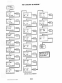
Mode 1 contains the accountability Information (MIS), Is
available in two different configurations. The first type of
accountability Is the type that has been available in previous
software versions known a PRICE LINE MIS - ten customer
settable price lines. These ten price lines are set In Mode
13, and are represented In Mode 1. The second, and newest
type of MIS Information available, will be referred to as
"PRODUCT INFORMATION MIS". UsIng the sequence MA,
MB, MC, etc. this will represent the number of products sold
for each selection by size. These two types of MIS are not
interchangeable, and only one type is available In a single
machine. The two flowcharts on the pages follOwing Mode 1
explain the sequence and meaning of both types of MIS.
Both of these configurations also support a audit
printout which Is automatically transmitted whenever
Mode 11s entered. See directions below for using this
function. This software version also contains 2 new
counte~ M7 & MS, which are counters that record the
number of".. vends for large and regular drinks,
respectlvely.
~ The counters for M7 & MS will count to a mulmum
of 9999 vends and will then roll over to 0000, and
continue to count
12. Depressing the START front panel selection switch
again will cause the machine to display additional
breakdowns of the vend totals by one of two methods.
The style of MIS information contained In the machine
is determined by the software. Which style Is present
can be determined by examining the software label·
see chart on page 1.04. The first type of accountability
is the type that has been available In previous software
versions· TEN CUSTOMER SETTABLE PRICE
LINES. These ten price lines are set in Mode 13, and
are represented in Mode 1. The second type of MI S
Information available, will be referred to as PRODUCT
INFORMATION. Using the sequence MA, MB, MC, etc.
this will represent the number of products sold for each
selection by size. The two flowcharts on the following
pages explain the sequence and meaning of both types
ofMIS.
The MIS Information Is a 'actory set option and is not
changeable in the field except by changing the entire logic
board!
•
The procedure.for retrieving basiC MIS information common
to both types manually is as follows:
If multiple price lines are being used· set the most
commonly used prices in the lowest possible price line
counter. These price line counters are set In MODE 13.
1. Open machine door. Tum 3 Amp (red) circuit breaker off then on. 13. Press coin return button to return to operate mode.
2. Depress the mode switch once so the display indicates
"MODE 01".
Note: The next mode can be entered by either pressing the
MODE switch InSide the door or by using the Increment
digit and next digit switches on the selection panel. .
3. Depress the large START front panel seleCtion switch,
and following a 4 second delay for the transmission of
MIS Information, the display will Indicate "MO ",
followed by " XXXX". This is the total vend count.
MIS AUDIT PRINTER
A new function supported by the AP213 allows the use ·
of a small battety powered printer to record the
accountability Information contained In Mode 1. The
printer should be settable to the following format:
4. Depress the START front panel selection switch again
and the display will indicate "M1
", followed by""
XXXXJOC". This Is the cash total taken by the machine.
1200bps, ASCII, S data bits, 1 stop, no parity, full duplex
5. Depress the START front panel selection switch again
and the display will Indicate "M2 ", followed by ".
XXXX')(X". This Is the cash value of aI/ discounts
given.
One recommended printer Is manufactured by Selko,
Model DPU-411.21BU.
6. Depress the START front panel selection switch again
and the display will Indicate "M3 ", followed by".
XXXXJOC". This Is the total value of bills taken.
1. Tum 3 amp (red) circuit breaker off. Swing out both
cup dispensers and lower logic board.
2. Locate P2 connector In center ofboard and plug 11
pin connector from printer onto P2.
TO USE THE AUDIT PRINTER FUNCTION:
7. Depress the START front panel selection switch again
and the display will Indicate "M4 ", followed by".
XXXX". This Is the total number of discount vends.
3. Restore power and preu mode switch one time,
dlaplay should show "",ODE 01".
8. Depress the START front panel selection switch again
and the display will Indicate "MS ", followed by"·
XXXX.xx". This Is the total cash value of large drink
vends.
4. Depress large "STARr, and all MIS Information
will be tnlnsmltted to the printer and then begin
showing the MIS on the display· see Step 3 on
previous psge.
9. Depress the START front panel selection switch again
and the display will indicate "MS ", followed by ".
XXXXJOC". This Is the total cash value of small drink
vends.
Automatic Products 213 V1 .8 0798 2.03
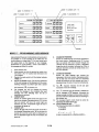
MIS FLOWCHART BY PRICELINE w~
~OTAL
xxxxxx
OISPLAY
11m
.09
IIPOI
.ESO COUNTER
DISPLAY SHOWS.
s~ows.
.09
PRICE L:~IE .,
NI
XXXX.XX
DISPLAY
;OTAL CASH W£TER
DISPLAY SHOWS.
:~OwS:
lie I9
XXXXX
IlCOI
• VENDS PRICE
~INE
.,
xnn
• vENDS PRIC! LINE
.le
CISPLAY SHOIIS.
N2
XXXI. XX
DISPLAY
DISCOUNT CASH IIETER
. ~0 .
MP02
PRICE
DISPLAY
N3
S~OWS.
~:~[
CASH VALUE OF OTH[RS
'2
S~.
xxxxxx
CASH VALUE S IlLL
DISPLAY 51\OWS'
DISPLAY SHOIS,
NC02
1100£
• VENDS
XXXXX
'~!CE
91
L1NE 12
DUPLAY SHOWS.
N4
xmxx
DISCOUNT VfNO CCUNttII
DISPLAY S"OW5.
IIP03
PRICE LINE .3
DISPLAY SHOWS.
lIS
. J9
xxxx.XX
CASH VAL uE LARGE DRNI
NC03
DISPLAY SHOWS.
116
.. VENDS
xxxXX
P~ ICE
LIN! 13
XXxx.xx
CASH VALUE
REG DRINKS
DISPLAY SHOWS.
IIP04
DlSPLAY SHOIS.
117
P.RICE LINE U
XXXX
LRG FR!! V!ND COUNT!R
DISPLAY SHOWS.
IIC04
DISPLAY S-S.
118
xm
: V!NDS
XXXXX
.~:CE
L• liE ••
REG FREE VEND COUNTER
STEPS REPEAT FOR IICas THROUGH IIOD9
Au\omO'lic ProduCt. 2'3
V'.2
0594
2.04
IIOTE: PRICE LINES (IlP01,
WPOZ. ETC) ARE SET AT
THE EJI) Of ICOO£ 13
MIS FLOWCHART BY PRODUCT INFORMATION .:C<:5S WODE 0 I
,
?RESS
157ART
I
DISPLAY SkOWS :
Mil
-C7AL
xxxmx
.. :~o
•
111
~OTAL
~
--
~: ~ NTE~
:nSPLAY SHOWS ,
XXXX.XX
CASH WE!ER
1
1
~
DISPLAY SHOWS:
XXXXXX
WA
VEND COUNTER
SELECTION I REGULAR
•
XXXXXX
•
112
XXXX.XX
-8 lIB
M3
XXXXXX
CASH VALUE OF I BILLS
•
DISPLAY SHOWS:
M4
xxxxn
OISCOUHT VEND COUNT!~
r-a •
115
xXXX.xx
CASH VALUE LARGe DRKS
•
DISPLAY SHOWS :
M6
XXXX.XX
XXXXXX
VEND COUNTER
SELECT:CN 2 ~ARGE
~
•
DISPLAY SHOWS'
xxxxxx
VEND COUNTER SELECTION 3 REGULAR ~
•
MF
XXXXXX
,
VEND COUNTER SELECTION 1 LARGE ~
•
M7
xxn
LRG FREE VEND COUNTER
IIG
~
xxmx
VEND COVNlER SELECTION • REGULAR DISPLAY SHOWS:
M8
XXXX
REG FREE VEND COUNTER
MH
~
Auto",,". P,OduC18 213 V1 .2 058.
XXXXXX
VEND COUNTER
SELECTION 5 LARGE
•
~
~
11K
xxxm
v~HO
COUNTER
SELECTION 6 REGULAR
•
-8
r-s
ilL
XXXIXX
vEND COUNTER
SELECTION 6 LARGE
•
DISPLAY SHOWS ,
1111
XXXXXX
VEND COUNTER
SELECTION 7 REIULAR
•
-8
liN
XXXXXX
VOID COUNTER
SELECTION 7 LAME
r-s
DISPLAY SHOWS:
JIOOE
"
l
VEND COUNTER SELECTION. LARGE 2.05
~
~
-
~
DISPLAY SHOWS.
I
XXXXX:
-8
DISPLAY SHOWS:
!NIl CI
DISPLAY SHOWS.
f
IIJ
r
DI SPLAY SHOWS,
~
DISPLAY SHOWS.
DISPLAY SHOWS:
CASH VALUE SWALL DRKS
DISPLAY SHOWS :
~
r
NO
XXXXXX
VEND COUNTER
SELECTION 5 RE&ULAR
•
DISPLAY SHOWS:
ME
DISPLAY SHOWS:
xxxxxx
VEND COUNTER
SELECTION 2 REGULAR
r
DISPLAY SHOWS:
•
III
DISPLAY SHOWS:
DISPLAY SHOWS:
Me
DISCOUNT CASH WET!R
~
DISPLAY SHOWS:
VEND COUNTER
SELECTION I LARGE
DISPLAY SHOWS:
DISPLAY SHOWS:
~
ACCOUNT AI I LI TT
RETRIYAL
PROCEDURE
iB
The automatic cycle can be disabled by removing connector
P12 from the logic board or by removing one wire from the
flush enable switch above the door lock.
It will stili be possible to cany out a manual flush using MODE
MOO-E 2 • TEST VEND
MODE 2 provides a means to allow one test vend. This test
vend Is NOT counted In MO In the MIS. If price line MIS is in
use, the vend wlII be recorded in the first available price line
that Is set to $0.00.
3.
MODE 4· SET PRICES FOR LARGE DRINK
1. Open machine door.
2. Depress the mode switch until the display Indicates
"MODE 02".
3. Depress the START front panel switch, the display
should Indicate "THANK YOU" and then scroll the user
message signifying that the machine Is In the normal user
mode.
Mode 4 now sets the seiling price for LARGE size drinks only,
Both Mode 4 and 5 must be set for the large and regular drinks
to vend correctly.
1. Open machine door.
2. Depress the mode switch until the display Indicates
"MODE 04",
4. The next vend will be a vend without credit
3, Depress the START front panel Switch, the display will
Indicate "PRICE ,00"
MODE 3 • FLUSH CYCLE
4. MODE 3 provides a method for route service or location
attendant personnel to perfonn a rinse of the brewer and
commodity delivery system during routine servlclng of the
machine. This flush cycle should not be operated while the
machine Is unattended, however other tasks, such as
replenishing cups may be done while the flush cycle Is
operating.
Use the next digit to move the bllnkJng cursor to the
required digit in the display. To Ina-ease the selected digit
press the Increment digit switch. The value of the digit
will return to "0" after "g".
5, When the desired price has been set on the display,
press the "STARr switch. The display will then Indicate
"SELECTION",
6. Depre!s the selection sWitches (nonnal panel buttons) to
assign the set price to the drink selections, The selection
LED will light up to Indicate that the price has been set
Repeat for all selections at this price.
1. Open machine door.
2. Depress the mode switch until the display Indicates
"MODE 03".
3. Depress the START front panel switch. The machine will
then show "OPT YIN". Use either the Increase or next
digit switch to change the Y to flashing.
4. Depress the START front panel $WItch. The machine will
then start a series of 3 flush cycles that will energize the
brewer, each valve and whipper In sequence.
5. 7. Depress the "STARr switch and the display will Indicate
"PRICE , ". To verify the prices depress the appropriate
selection switches, The prtce will be displayed for each
selection pressed. The LEOs will remain on until a new
mode Is entered.
8, Depress the "STARr switch and the display will retum
to "MODE 04",
Approximate run time for the flush cycle Is one and one
half minutes.
6. At the end of the flush cycle the lamp on thecupwell
bezel will go out while the display will continue to Indicate
"MODE 03" and the Y that was changed above will reset
toN.
•
SETTING PRICES TO 0.00 WILL SET A SELECTION
TO FREE VEND.
I
SETTING A PRICE TO 99.99 WILL DISABLE A
SELECTION AND CAUSE THE MESSAGE "MAKE
ANOTHER SELECT/ON" TO APPEAR WHEN THE
SELECTION IS PRESSED. THIS IS USEFUL FOR
BLOCKING UNUSED SELECTIONS OR DISABLING A
SELECTION WHEN IT IS OUT OF ORDER.
AUTOMATIC FLUSH CYCLE
The machine Is equipped with an automatic flush cycle which
Is carried out automatically every 12 hours. The automatic
flush will occur as long as the autoflush enable switch Is
connected to the logic board and the door Is closed. The
volume of the water dispensed during the flush cycle is preset
during manufacture and should not be adjusted. If you
experience problems with the cycle, either due to Infrequent
service or volume of liquid dispensed, you may reduce the
duration of the valves' operation.
• DO NOT ATTEMPT TO CHANGE THE CLEANING CYCLE
CHANNELS,
MODE 5 • SET PRICE REGULAR SIZE
This mode Is used to set the prices for the regular size drink.
They are a completely separate set of prices from the large
prices. Both sets of prices must be set for the machine to
operate correctly. The procedure Is Identical to MODE 4,
•
The automatic flush will operate every 12 hours from the :ast
time that the machine was powered up, If the machine Is being
used at the end of the 12 hour period It will wait for 10 minutes
of complete Inactivity before carrying out the cycle.
AutDmatic Products 213 V1 .6 0798 2.06
If you are disabling a selection by setting the price to
99.99, you must set this price in both Mode 4 & 5.
should appear in the range 00 throU'~h 24. 29. 38 o~
41. This indicates that the switch is working
correctlv. This test may be repeated as many times
as necessary to test any questionable switches.
MODE 6 - DIAGNOSTICS
Mode 6 will provide a means to test the scrolling displav
segments. LEOs on the selection panel. and all logic level
switches. This function includes a means to test all
selection panel switches.
1. Open machine door.
2. Depress the mode switch until the displav indicates
~MODE 06" .
3. Depress the START front panel switch. The scrolling
displav will have all segments on and all LEOs will be
illuminated until MODE 6 is exited.
CHANNEL TEST
Modes 7 & 8 provide a means to test the function of a
specific channel without running an entire vend. This
function allows for testing a specific device - motor. valve
etc for trouble shooting purposes. Mode 7 will test a
channel for the duration time that channel is set for. while
Mode 8 will continuouslv provide power to the device until ·
the power is removed bV pressing the START button again.
MODE 7 - CHANNEL TIMED TEST
4. The displav will then indicate all the closed logic level
switches bV switch number. one after another. This
facility. along with the list of switches. can be used
to locate problems in the machine. See the
troubleshooting section in the service section of the
manual.
MODE 6 SWITCH LISTING· NORMAL OPERATION
WILL APPEAR IN
SWITCH' INDICATION
NORMAL OPERATION
23
RIGHT START SWITCH
N
24 or below faulty membrane (selector)
N
discount switch
25
YIN
26
auto flush enable switch
YIN
27
bucket switch activated
N
CUP SENSOR INPUT
28
YIN
SELECTION 3 MILD
29
N
31
LEFT START SWITCH
N
brewer water switch
33
Y
y.
34
brewer cvcle switch
35
brewer delav switch
N
36
not used
N
37
logic jumper - heater voltage
Y
SELECTION 3 MEDIUM
38
N
40
heater tank level probe (ELLCI
N
SELECTION 3 STRONG
41
N
46
REGULAR CUP PRESENT SWITCH
Y
47
LARGE CUP PRESENT SWITCH
Y
5. 1. Open machine door.
2. Depress the mode switch until the displav indicates
"MODE 07".
3. Depress the START front panel switch. The displav
will indicate "CH 00".
4. To select a channei use the next digit switch and incr.... digit" switches to select the desired channel number. 5. Depress the START switch and the selected channel will operate for the normal vend duration time. 6. When the selected channel is finished the displav will indicate "MODE 07" • MODE 8 - CHANNEL CONTINUOUS TEST
1. Open machine door.
2. Depress the mod. switch until the displav indicates
"MODE OS".
3. Depress the START front panel switch. The displav
will indicate "CH 00".
At the end of the diagnostics the displav will indicate
~MODE 06".
4. 1. To sel.ct a channel· use the next digit switch and
incr.... digit" switches to select the desired channel
number.
SELECTOR PANEL TEST
Access MODE 6 as instructed above.
5. 2. Press START. and observe the numbers that appear
in scrolling displav. No numbers below 24 and
29.31.38 and 41 should appear. These are all
selection switches and ~ should be closed during
nonnal operation.
3. Record all numbers that appear. If you suspect you
have a defective selector panel switch. press START
again. and immediatelv press the suspected mal
functioning selection button. Observe the numbers on
the scrolling displav. Compare these numbers to the
list of numbers recorded above - a new number
Automatic Products 2.'3 V 1.2 OS••
2.07
Depress the START switch and the selected channel
will be turned on. It will stay on until the START
switch is depressed again. The displav will then
indicate "MODE OS~.
MODE 9·UPLOAD SETTINGS TO MACHINE
At present the only device capable of being used to upload
data to the machine is an IBM compatible computer or
another machine.
1. Open machine door.
2. Depress th.e mode switch until the display Indicates
~MODE
Connect the programming device cable to P2 on the
con.t rol board.
4. Depress the START switch before sending the file to
the machine control board.
Depress the START switch on machine A.
5. The scrolling display will go blank on machine B.
When the scrolling display returns, the file transfer is
complete.
•
09".
3. 4. DATE CODE ..
ORDER 1/ ..
CHMiT 11
5. The display will remain blank during the file loading
time. At the end of the file loading the user message
will scroll on the display again.
•
MODE 1 Q·DOWNLOAD SETTINGS FROM
MACHINE
A t present the only device capable of being used to
download data from the machine is an IBM compatible
computer or another machine.
1. Open machine door.
2. Depress the mode switch until the display indicates
"MODE 10".
3. Connect the programming device cable to P2 on the
control board.
4. Depress the START switch. This starts sending the
file to the external programming device.
5. The display will remain blank during the file sending
time. At the end of the file sending the user message
will scroll on the display again.
2. Put the machine which has already been set up
correctly (machine A), into mode 10.
3. Put the machine to be set up (machine B) into mode
9. Machine B needs to be in an in order condition to
receive the download (loaded with cups, full of
water, bucket .switches free) . Depress the START
switch.
Automatic Productw 213 Vl . l 0394 >
OOCbl8F~ ;i··
For all model 213. the first three digits of the chart
number MUST match for a successful transfer of
information. In the example above, the first 3 digits
are OOC. This means that the settings in this machine
would transfer successfully to any other machine
whose chart number started with OOC.
The information in the data'transfer file between machines
or the computer and the vending machine in either direction
is:
PRICE SETTING INFORMATION -Includes information
from MODE 4 for single oup machines and MODE 4
&& 5 for Dual Cup models.
CONFIGURATION - Exactly dl!plicates the settings in
MODE 11.
CHANNEL SETTING - Copies the settings of all
ingredient channel settings located in MODE 12.
PAYMENT OPTIONS - Copies the settings of all
options located in MODE 13 for payment and other
functions.
It is also possible to transfer the settings and data from one
machine to another, using a special connecting cable (part
1/ 33784) . The procedure is as follows:
Connect each end of the cable to the two P2
connectors on each machine control board.
.•. . a5~:$:11~~:·':;:
INFORMATION CONTAINED IN TRANSFER
MACHINE TO MACHINE UPLOAD/DOWNLOAD
, .
Due to the complexity of the information that is
transferred during the upload or download, some
precautions must be observed. The information that
is required is located on the paper label on the main
program chip located on thel.o gic board. The diagram
below explains the information contained on the
label.
DISCOUNT SELECTION - Copies the setting of the
discount bits in MODE 14.
CAUTION: DOWNLOAD WILL NOT TRANSFER THE
10 PRICE LINE SETTINGS FROM THE END OF
MODE 13. THESE ARE CONSIDERED PART
OF THE MANAGEMENT INFORMATION
SYSTEM (MIS). NO MIS INFORMATION IS
TRANSFERRED. THE STANDBY SCROLl.ING
MESSAGE IS NOT TRANSFERRED.
For additional information about computer transfer
capabilities, contact Technical Services Department.
2.08
MODE 11 - MACHINE CONFIGURATION
DEFINITION OF CUSTOM SELECT COFFEE
The function of MODE 11 is to determine the type of
machine the software is installed in and what fresh brew
options are available. Also included are the options that
control the dispensing of cups and operation of the cup
dispensers when one oabinet is empty.
CUSTOM SELECT COFFEE (abbreviated CSC) is the name
of the selection assigned to at least the third prime
selection. A number of new ohannels are available which
allow you to create a custom drink using existing products
in the maohine. A few examples of this might be: Cafe
Mocha defined as brewed coffee combined with whipped
chocolate or Balanced Biend, a half regular, half decaf fresh
brewed coffee. This seleotion - CUSTOM SELECT COFFEE
allows the operator to create their own special drink.
•
THE FUNCTIONS FOR MODE 11 ARE VERY SPECIFIC
AND DIFFERENT FOR EACH OF THE CANISTER
RACK CONFIGURA TIONS.
•
MAKE SURE YOU ARE USING THE CORRECT MODE
11 TABLE FOR YOUR SPECIFIC MACHINE - SEE
CANISTER RACK INDEX CHART ON PAGE 1.01
1. Open machine door.
2. Insert security key into the service key switoh, turn
·the switch to the "on" position and then back to the
"off" position. This allows the key to be removed and
prevent it being left in the machine in error.
•
The correct function of the key switch is: on then off
- the key should always ·be in the position where key
can be removed.
3. The display should indicate "MODE 11".
4. Depress the START switch. The display will indicate
"CONFIGH/B/C". The "H" should be flashing to
indicate that the machine is set up as a 213 hot drink
machine .
5. If the "H" is not flashing , after having just installed a
new oontrol board or new software for example,
press the chang. digit switch until it is. Then depress
the START switoh. The machine will then jump
automatically to mode 16 to load the default values
appropriate for the 213 machine (see page 3.20xxx
for additional information on board replaoement).
6. If the "H" was flashing correctly continue with the
configuration by depressing the START switoh.
•
FOR ADDITIONAL INFORMATION · ON CUSTOM
SELECT COFFEE - SEE MODE 1 2
OPTION !i,6,7
7. 8. These three options control the function of the dual cup
dispenser. Qption 5 allows the choice between a maohine
containing two size oups or one Which has a larger quantity
of a single size cup. Options 6 & 7 allow control of the cup
dispenser in the event that one size cup is not available to
vend. If either or both of the options are set to "N" and
that oup size is selected but not available, the scrolling
display will show "USE OTHER CUP SIZE" . If either or both
of the options are set to "Y" and the correct change is not
available, then a drink may not be delivered.
The machine will then advance through a series of
questions. Each selection is made by
depressing the change digit switch until the "Y" (yes)
or "N" (no) is flashing and then activating the
selection by depressing the START switch The
fI.ashing charaoter indicates the selected ohoice. The
charts at the beginning of rack configuration section
provide the choices available for e.aoh type of raok.
••"en
When the START switch is pressed for the final
question the display will indicate "MODE 11".
Note: It is important to return to the "MODE 11" on the
display to ensure that the new values are loaded.
Automatic Produm 213 V1 . 1 0394 2.09
INCREASE FLASHING DIGIT
CHANNEL TEST (MODE 12)
MOVE FLASHING DIGIT
,~-
( Decaf
[ Cl5C _1
( esc
.21' s;c
. ( TMlSGC
S.1...et
0001
crOg:]
OC'C1
[~~aa01
[~S;C
Cl
ooc~
(~
OJ
Drr,....
Select. ...""'tl ....
~
RarT.
-€,..-
a
!kart,
.g.
~
ENTER
The directions for accessing the ingredient channels in
MODE 12 are as follows:
MODE 12 - SET TIME CHANNELS
The primary function of Mode 12 is to allow aocess to the
numerous channels available for each selection. Each
selection in the maohine has a number of channels
organized into a RECIPE - the oorrect arrangement of
ohannels in eaoh recipe is what creates a specific drink. For
example. one of the simplest recipes is for a hot chocolate
selection. The list of the channels required for a hot
ohocolate selection are:
Channel
Channel
Channel
Channel
02
03
67
68
1. 2. 3. 4. 5. Hot vend cycle
Cup drop start pulse
Chocolate water 8. whipper
Chocolate auger
6. Each of these channels. when combined in the correct
order. in the appropriate amounts. will deliver a cup of hot
chocolate. By increasing the number of channels available
for a selection. the flexibility of that selection inoreases.
The .elet:tIon th., hu th/6 muimum 1IezI~ /6 nemed
·CUSTOM SELECT COFFEr end /6 the tNnI ( .nd
occulonelly the fourth) prime .elecdon on the leh .ide 01
the .electo,
Because each of the five prime
selections are directly affected by the setting of the first
four options in Mode 11. the function of the "CUSTOM
SELECT COFFEE" is directly affeoted by whether the
machine has fresh brewed coffee or freeze-driedooffee.
The "CUSTOM SELECT COFFEE" Is abbreviated as CSC in
the ohannel lists.
7. pe"'.
•
8. 9. ALL ADJUSTMENTS TO INGREDIENTS ARE MADE
FOR THE LARGE SIZE DRINK. THE SMALL SIZE
DRINK WILL HAVE THESE ADJUSTMENTS MADE
AUTOMAnCALLY BY THE VOLUME SETTING IN
MODE 13.
Automatic Products 213 V1.1 D394 10.
2.10
Open machine door..
Insert security key into the servioe key switch. turn
the switch to the "on" position and then back to the
"off" position.
Depress the mod. switch until the display indic.ates
"MODE 12".
Depress the START switch. The display will indioate
"CH 00".
To select a ohannel use the next digit switch and
Incr•••• digit" switches to select the desired ohannel
number. See figure .above for location of switches.
Depress the START switch and the start time will be
displayed in the following format - "START 00.0" .
This is the time from the beginning of the vend cycle
to when thll channel starts.
To change the start time. the next digit switch can be
depressed repeatedly to move the flashing character
to the left. to the digit to be changed and the
fncr•••• digit switch depressed to increase the value
of the digit.
When the required start time has been set. depress
the START switoh. This will change the previous
start time to the new start time and advanoe to
display the duration time. The display will be in the
following format - "OUR 00.00".
The dur.tion time can be changed by use of the n.xt
dfglt and incr•••• digit switches as explained in step
7 above..
When the required duration time has been set.
depress the START switoh. The new duration time
will replace the old time. ff the channel has a modifier
the display will indicate "MOD 0.00". If there is no
modifier the display will indicate "MODE 12".
CUSTOM SELECT COFFEE
11. The duration sets the ingredient throw for the
medium strength or middle selection e.g. regular
coffee. The modifier value is the percentage increase
and decrease in ingredient throw for the strong and
weak selections on the selection panel. The modifier
is set by means of the n.xt digit and Incr•••• digit
switches. By depressing the START switch the new
modifier will replace old one. The display will then
indicate "MODE 12".
CREATING YOUR OWN RECIPE
Since the components on the Motor Control Board are
shared to operate different drink selections, attempting to
operate two ingredients at the same time will create 8
contlict. Therefore, some rules must be followed when
creating the recipe for your CUSTOM SELECT COFFEE. The
oharts on th, previous pages contain times that have all
these oalculations considered. As long as your times do not
exceed the durations or modifiers by an extreme amount,
you should not have to perform any of these caloulations.
12. The selected channel can be tested by depressing the
CHANNEL TEST swltoh (middle light). The channel
will be turned on for the normal vend duration. The
display will indioate "MODE 12".
1. •
Eaoh channel to be tested must be "ENTERED"
before it is tested - otherwise the test will return to
the last channel tested.
2. Note: It is important to return to the "MODE 12" on the
display to ensure that the new values are loaded.
3. 4. All times listed are approximations, and should be adjusted
for proper gram throws which are dependent upon regional
variation in product and customer tastes. To assist you, a
chart which provides approximate gram throws for normal
products are available in Appendix I. While adjusting times,
especially START or DURATION times of either produot or
water, the primary premise for correct operation of the
machine will depend upon maintaining the proper sequence
of liquid and ingredients: dry Ingr.di.nts ahould alw.y. fall
Into flowing liquid .nd ahould alw.y. b. followed by
flowing liquid to aohl.v. a compl.t• •nd thorough rln•• of
the mlldng bowl or mixing chann.l. Once the comict rinse
time for a water channel has been set, the correct oup level
should be set using the metering screw on the respeotive
commodity valve.
Only.!!!l!!. prime selection (LG regular coffee, fresh
brew decaf, all FD augers, chocolate and soup) motor
should be on at a time.
Only .!!!l!!. prime selection (same as '1) water valve
may be on at a time.
No trough whipper (channels 15,24,33,47,61) may
have a START time less than 1,9 seconds.
A minimum of .1 second should be allowed between
one device (motor or valve) turning off and the next
similar device turning on. This is defined as the
SEPARATION TIME.
The only exception to rule " is the large grinder. The large
grinder oan be used in oombination with any other prime
seleotion motor beoause it has a separate oontrol circuit. As
an example, below is list a sample caloulatlon to determine
the start time for the seoond coffee in a half regular, half
deoaf for an 8 % ounce seleotion using a dual hopper (DH)
swing out braoket.
All the ohannels listed in eaoh of the recipes are available
for use. However, some of the channels will have 0.00
listed for a duration. This indicates that a channel is not
being used in the ourrent drink, but may be used if
required.
FOR ADDITIONAL INFORMATION ON CHANNEL USAGE
SEE APPENDIX IV - CHANNEL APPLICATION CHART
START TIME
DECAF LG CANISTER
'" 0.0
1
DURATION
DECAF LG + 2
2.40 seoonds + 2
= HALF DECAF TIME
= 1.20 seconds
2
MODIFIER DECAF LG
=.25 (25%)
MODiFIER x DURATION
;, ADDITIONAL TIME DECAF
LG CANISTER IS ON
.25 x 1.20
The recipes for selections using brewed coffe.e listed in
each of the configurations listed in Section 1 of this
manual, are factory set to be used with all the water being
delivered to the brewer via the brew water valve. The Open
Cylinder Delay (channel 9) is adjustable to pause the
brewer to allow all water for brewed drinks to be delivered
through the brew water valve. If makeup water is added to
any of the brewed coffee or CSC fresh brew drinks, all
times for the total water delivered to the cup will have to
be readjusted.
SEPARATION TIME
3
= .10 4
Using the above figures the minimum start time for the
regular LG motor would be:
LG
START ST ART + DURATION + MODIFIER + SEPARATION
+4
1
+
2
+
3
1.6
0.0
+
1.20 + .30
+.1
=
The minimum start time for the regular LG motor (channel
6) would be 1.6 seconds, but please note if the duration or
modifier is changed, then the START time for the LG motor
should also be changed using the new times in the same
formula.
""tom.t1c Produi;t8 213 V 1. 1 0394 .30
2.11
MODE 13 - SET OPTIONS price i. obtein.t/ by multiplying the "end pdt:e by
the _count fecto, e.lI. 50C Jl .80
4OC. The
r/i$t:tJunted pdt:e will b. in effect wfI." til.
_count .witch i6 op.,eted. Tn;. m...ell.
TepIe_ the p,.tliDUlIy u_ed "VOL D" meuege. MODE 13 contains a series of options and settings that
provide the operator control over several payment options
and settings that control the size of the regular cup. When ,using any of the YIN (Yes/No) options, the letter that is flashing is the current setting of the option. Mode 13 wiN
now pmvide the option of .etting e . . .,.t. rr,.count fo,
the le'11e end Teflule,
cup. =
.b.
1.
Th. DISCOUNT PERCENTAGE to, th./e'11. end.mell eTII
Open , machine door. Insert security key into the
service key switch, turn the switch to the "on"
position and then back to 'the "off" position.
2.
Depress the mode switch until the display indicates
"MODE 13".
3.
Depress the START switch. The machine will then
advance through a series of questions and options.
Each YIN selection is made by depressing the change
digit switch until the "V" (yes) or "N" (no) is flashing
and then activating the selection by depressing the
START switch. The following questions are indicated
on the display:
FORCE
now.pIt. "DISCL" eppli. . only to the LARGE drink••
end "DISCII" epplill$ only to the REGULAR ';ze drink.
Fo, the D"count .witch to eet .. e ".. vend rNitt:h.
both ".,cenuga must be ••t to 100" (1.00/. Both
tile mechi". . ." .
ptin:enteg.. • ,. • ., to 1.00
the fectOTY. H you desi,. to vend ody one cup .ae toT
f,... then the " . . • iz••hould b. nt to 700" end the
thet must be puTChe.ed .houltl b. . .t to 096 (.00/.
Oth., combinetio". of pen:entegu cen b. used to
t:Tefi. e di6count fo, I!$ing your own oup. 0' eny otll.
type of pmmotion. howe.,., .n .electio". .hould b.
t..ted with both .be drinb to _UTe co,TIIt:t o".,etion.
w""',
.a.
YIN Y - Forced i.e. User must make a vend
before change is returned
N - Normal
FREE
YIN MS1600 YIN
Depress the START switch. If the displey ,etums to
MOOE 13, then the machine is equipped with
PRODUCT INFORM.1 TION MIS end you tmly flXit tile
.lITVicemode. IfthedispleyindiclItu ·PRICE' .XX·
til." the tmlchine contains PRICE LINE MIS• ."d you
should continue with the setting of the ten price '
lines. PRICE1
.XX is the price setting for the first
price line. There are ten price lines that can be set to
the required values. The control will then increment
the count every time a vend is made at that price (or
an equivalent price obtained by discounting a higher
price).
6.
Set the required price using the incr.... digit and
n.xt digit buttons.
7.
Depressing the START switch will increment through
the 10 price line values:
Y - Free vend enabled on all selections
N - Normal prices apply
Y - European Executive changer installed
N - US changer installed
ESCROW YIN Y - Bill validator will esorow any bill that
takes the credit above the highest vend
price. No further bills will then be accepted.
If the coin reject is pressed the bill will be
returned.
N - Bills are stacked immediately.
MULTI YIN 5.
Y - More than one vend can be made before
change is returned.
N - Single vend - Change is returned
immediately.
DISCL 1.00 Any MOl••electiDn enebled fo, rr,.r;ount in Mode 74 will b. dinounted by the fecto, • ., in W. thplq. Th. _r;ount price ;.
obUined by multiplying the "end price by
the di6t:tJunt fecto, •. g. SOC Jl.80 .. 4OC.
The m.t:tJunted price will be in effect when
"PRICE9 .XX"
"PRICEO
.XX"
Each pric. line can be set to a different value. Leave
any unus.d prices set to .00.
the "count .wItch " opeRted.
•
FREE CT 00 This option allows a free drink after a given
number of vends. The number in the display
can be set between "01" (every vend) and
"255" (every 255th vend is free). If the
number is left at "00" no ,free vends will be
given.
8.
VOLUME.75 This setting expressed as a peroentage (%l
allows the setting of the regular as
compared to the large drink - example:
'20z.(large drink) X .75 (75%) - 90z
(regular drink). See chart on next page for
conversions.
Depressing the START switoh completes the
selection and returns to the beginning of the mode.
The display will indicate -MODE 13".
Note: It is important to return to the "MODE 13" on the
display to ensure that the new values are loaded.
I
VOLUME % CHART ON NEXT PAGE r:r
DISCR 7.00 Any ,"ule, .in .election _bled to,
_count in Mode 14 will b. di6counted by
the fecto, • ., in W. -tMy. The _count
Autc>madc ProcIu... 213 V1.2 0594 The first available price line set to .00 will record all
MODE 2 test vends, all 100% discount vends and all
FREE CT (winner) vends.
_
2.12
I
.
VOLUME % CHART FOR REGULAR CUP SIZE
2) READ
ACROSS &
ENT~R THIS
%IN
Mode 13
Volum. %
85%
83%
80%
78%
75%
72%
70%
69%
65%
-"i%
60%
58%
55%
MODE 16 - LOAD STANDARD SmlNGS
1) FIND LARGE CUP VOLUME
HERE AND READ DOWN
TO SMALL CUP VOLUME
The function of Mode 16 is to provide a means to install
new software or to return the settings in a machine to the
original factorY settings contained in the EPROM. This
process is commonly known as initialization. These settings
can be confirmed by cheoking the label on the program chip
• see chart on page 1 .04 for additional information. If an
OUT OF ORDER Ml0 code appears on the scrolling
display. the only way to eliminate this code is to perform a
Mode 16 reset. The information changed during this
initialization procedure is the same as contained in a
machine to machine transfer· see page 2.08 for a list of
this information. The Mode 16 reset can also be considered
a wsafety net w• which will allow you to eliminate any
incorrect or scrambled information whioh is preventing the
machine from operating correotly. In most cases. this will
restore the machine to an operating condition.
Large cup size (ozl
9
10
11.5
12
7.li5
85
8.25
9.7"
lQ2
7.2
B.O
9.2·
9.0
8.6
8.25
8.00
9.6
7.0
6.75
7.5
6.3
7.0
5.9
6.5
7.5
5.4
6.0
.7.0
6.9
5.0
5.5
63
9.0
8.4
8.25.
7.8
7.2
7.0
6.6
1. MODE 14 - SET PIS COUNT BITS
Mode 14 permits setting which drinks are permitted to be
discounted when the discount switch is on. If consistent
problems are encountered with the discount switch being
left on .,ccidentally. and drinks being given away free
unintentionally. the .asiest method to disable the switch is
to access Mode 14 and press START twice. This will clear
all previously set discounted selections.
1. Open machine door.
2. Insert security key into the service key switch. turn
the switch to the ·on w position and ~hen back to the .
·oH w position.
3. Depress the mod. switch until the display indicates
·MODE 14w.
4. Depress the START switch. The display will indicate
·SELECTION w.
5. All previously set discounts will be reset. Depress the
selection switches (normal panel buttonsl to set the
drink selections to be available for discount. The
selection LED will light up to indicate that it is
discounted. If the selection is pressed again the LED
will go out again to indicate that it Is not disoounted.
6. NOTE: Changing the options in MODE 11 may require
resetting the discount assignments.
•
Entering MODE 14 and pressing START twioe will
clear all selections previously set for discount.
MODE 15· NOT USED ON THE 213 HOT DRINK MACHINE
Automollc ProduCU 213 V1.2 0514 2. Insert security key into the service key switch. turn
. the switch to the ·on w position and then back to the
·off w position.
3. Depress the mode switch until the display indicates
wMODE 16".
4. Depress the START switch and the display will
indicate wMODE 16" again. While it appears nothing
has changed, you have entered Mode 16.
5. In order to prevent accidental loading ohhe standard
times and settings, it is necessary to enter a code
number or password. Using the Increas. digit and
n.xt digit switches change theW 16 wto w27 w and then
depress the START switch. The display will go blank.
•
Depress the START to oomplete the selection. The
. display will indicate wMODE 14w.
2.13
Open machine door.
Changing the W16" to a "27W should be considered a password that is the only way to reload the factory standard times. To confirm that MODE ' 16 was properly done turn power off and back on. If . configuration and the val u.s in MODES 11.12 and 13 remain the same. then the reload was correctly done. 6. When initialization and loading of the standard values
is complete the display will scroll the user message
again.
7. Return to mode 1 1. recheck configuration and set the
machine options.
•
If you have been supplied with a ·CUSTOM CHIP"
(indicated by a letter higher than J in the fourth
position of the of the CHART , as shown in the
diagram on the page describing the EPROM label) you
are reloading the times and settings provided when
the wCUSTOM CHIp· was created.
t.OOE 17-eu~so~
LEFT "8"
IIDOE 17- FO~WA~OS "C"
MJOE 17- CURSOR RIGHT .. A ..
MOOE
17-BACI<:WAROS "0"
/
eorfee
1"• ...-1. wcney
[ De=f OOC~
( 5U\1v
[ SU\lV Sob
( esc
'1
0001
[ esc
r21SGC
raO[Q)1
DOra
[ TeDlSGC
I
I
SouplSGC
o onOn
ooral
Ol
D1
CMc
~
I ect. 01"""1
nc
Mlec:t. A4G1t.rv_
"'"_ Start.
~
SU.rt
,.....,
CP
ENTER
MODE 17 - PROGRAMMING USER MESSAGE
Approximately 85 spaces including blanks and punctuation
are available for a user message to be loaded Into the
scrolling display by using Mode 17. For best results leave
5-6 spaces blank at the beginning of your message.
Doubleoheok for correct spelling - errors in the middle of
the message are difficult to correct.
1. 2. 3. 4. Open maohine door.
Insert seourity key into the service key switoh, turn
the switch to the "on" position and then baok to the
"off" position.
Depress the mode switch until the display indioates
"MODE 17".
Depress the START switch. The first nine characters
of the user message will be displayed with the cursor
(flashing character) at position eight and a speoial
8. CHARACTER FORWARD
Switch "C" (coffee strong) oontrols the characters at
the oursor location. Depressing switch "C" for less
than one second will move forward through the
character set one character at a time. If depressed
longer the rate of movement will speed up. When a
character has been correctly set simply move on to
the next character.
9. CHARACTER REVERSE
Switch "0" (light medium) also controls the
characters ilt the cursor location. Depressing switch
"0" for less than one seoond will move baokward
through the character set one charact~r at a time. If
depressed longer the rate of movement will speed up.
10. The
start character (
5. 6. 7. S ) at position one.
The message can now be changed by moving
through the message to the oharacters that need
ohanging and then selecting from the list of
characters and symbols.
CURSOR RIGHT
Switch "A" (coffee regular) moves the cursor to the
right in the message. Depressing switch " A" for less
than one second will move the cursor right one
character at a time. If depressed longer the rate of
movement will speed up.
CURSOR LEFT
Switch "8" (light mild) moves the cursor to the left in
the message. Depressing switoh "8" for less than one
seoond will move the cursor right one character at a
time. If depressed longer the rate of movement will
speed up.
Automltlc Products 213 V1.1 0394 (S )
character indioates the left and right
boundaries of the user message.
11 . The ( ~) character must be entered to indloate the
end of message to be displayed. Otherwise the
display message would ignore the boundary character
and may scroll some charaoters that do not belong to
the character set.
12. The message program mode should be exited by
depressing the mode switch only.
13. VALID CHARACTER SETThe following characters are available: A through Z o through 9
$'<>"+,-.I?
~
A blank is represented by a flashing underline _
2.14
APPENDIX I • GRAM THROWS AND WATER VOLUMES
RECOMMENDED GRAM THROWS
70z
8.25oz
100z
1202
COFFEE
LIGHTENER
SUGAR
FDCOFFEE
FDTEA
FBTEA
SOUP
CHOCOLATE
SGC
7-7.5
1.5-2
5-5.5
1.2
1.2
2.5
5-5.5 ·
20-22
14-15
8-8.5
2-2.5
6.5-7
1.5
1.5
3-3.25
9.75-10.25
3.0-3.4
6.8-7
1.8
1.8
4.0
7.0
28-31
23-24
11.5-12.5
4±
9-10
2-2.5
2-2.5
4.5
7.5±
33-36
26±
•
454 GRAMS • ONE POUND ~ .5
24-26
17-18
examine your Ingredient package for ingredient amounts. Use product manufacturers recommendations for ingredient throws. All gram throws above are apprOximations. ANlays take three test and average for best accuracy, except for products like chocolate where the product quantity exceeds scale capacity. Some lightener Is super fine and wtll bind up behind louvers In spout - solution Is to remove louvers or replace spout. Changing from "SANKA" to no name fd coffee louvers must be removed. Soluble Gourmet Coffees MUST USE 180 RPM MOTOR to deliver sufficient product during the allotted time. Zero scale before starting - nickel weighs exactly 5 grams WATER VOLUME IN CUBIC
CEmIMfi;TERS ':;/. S CLIP SIZE
.- . .
"
Nominal size
Volume to brim (cc)
.
701,.
8.25 OZ.
90Z.
10 OZ.
12 OZ.
205
235
270
290
345
PRACTICAL VOLUME FOR VENDING ee's)
•
COFFEE BREWED/SOLUB.L.E
175
205
225
260
315
TEA-BREWED
175
205
225
260
315·
TEA - SOLUBLE
175
205
225
260
. 315
SOUP
175
205
225
260
315
CHOCOLATE - WHIPPED
150
175
190
220
270
SGC - WHIPPED
150
175
190
220
270
• FB TEA 12 OZ.
Automa1lc Products 213 V1 .6 0798
= 250ee from FB Tea Water valve + 65cc make up water
30 ee = 1 ounce liquid measure
2.15
APPENDIX II: 213 SWITCH NUMBERS SELECTOR PANEL SWITCHES
Switch II O••crlptlon
00
01
02
03
04
05
06
07
08
09
10
11
12
13
14
15
16
17
18
19
20
21
22
23
24
29
31
38
41
Switch II
25
26
27
28
30
32
33
34
35
36
37
40
46
47
Seleotion4. mild
Selection 4. regular
Selection 5. mild
Selection 1. mild
Seleotion 1, regular
Selection 1, strong
Selection 2, mild
Selection 2, regular
Selection 2, strong
Selection 4, strong
Selection 5, strong
Sugar, low
Sugar, medium
Sugar sub. low
White,low
White, medium
White, high
Sugar, high
Sugar sub, high
Selection 7, chocolate
Selection 6. regular
Selection 6, soup/SGC
Sugar sub, medium
Right START
Cancel
Selection 3, mild
Left START
Selection 3. regular
Selection 3. strong
Automatic ProduC1a 213 V 1. 1 0384
2.16
Oe.cription
Discount switch
AutoFlush enable interlock
Waste ,!nd grounds bucket-AC Present
Cup Sensor input (N.O.)
Mode
Security key
Brewer water enable switch
Brewer cycle
Brewer delay enable switch
Heater thermostat #1
Heater thermostat #2
Water present - Probe
Cup present switch #1
Cup present switch #2
APPENDIX III: "OUT OF ORDER" CODES
The ·OUT OF ORDER" codes that appear in the scrolling display indicate which of the conditions are causing the machine to be out
of service. The codes are additive and may indicate that more than one condition exists. EXAMPLE : Code M22 equals M20 plus
M02: this would indicate that one of the buck.et floats has deactivated its switch and the water level in the tank is low. Both
conditions must be corrected before the machine will return to service .
Code
Out of Cups
M01
MOl
M02
M03
Ml0
Ml1
M12
Ml3
M20
M2l
M22
M23
M30
M3l
M32
M33
Out of cups
Out of cups
No Water
M02
No Water
No Water
EPROM Mismatch
EPROM Mismatch
EPROM Mismatch
EPROM Mismatch
Out of cups
Out of cups
No Water ·
No Water
Out of cups
Out of cups
No AC IFloat hlghl
M20
No Water
No Water
Out of cups
Out of cups
EPROM Mismatch
M10
No Water
No Water
- EPROM
EPROM
EPROM
EPROM
Mismatch
Mismatch
Mismatch
Mismatch
No
No
No
No
No
No
No
No
AC
AC
AC
AC
AC
AC
AC
AC
IFloat
(Float
(Aoat
(Float
(Aoat
(Aoat
(Aoat
(Aoat
high)
high)
high)
high)
high)
high)
high)
high)
NOTE: If a code other than one of the above shows in the scrolling display, MODE 11 is probably configured incorrectly and
should be checked immediately. The only way to eliminate an Ml0 code is to perform a Mode 16 reset - see-page
2.13.
AUlomwc P,aduCU 213 V1.1 0394 2.17
ill
.,.
,CAUTION: THE FOLLOWING PROCEDURES
REQUIRES THAT THE MACHINE HAVE POWER
APPLIED AND APOTENTIAL ELECTRIC SHOCK
HAZARD EXISTS
commodity chutes and reinstall the hum.idlty bar and the
commodity chut~s .
Using warm water and detergent clean other Interior
surfaces, wipe with a damp cloth and wipe dry.
Remove cupwell, grate and vend door, clean with hot
water and detergent. Rinse with clear water and dry with
clean cloth or paper towel. Wipe Inside of door and clean
vend door guides. Replace cupwell, grate and vend door
In machine.
Remove disposable bag containing spent coffee grounds
and rinse bucket with hot water and replace liner. Empty
and scrub waste bucket. Rinse with anti-bacterial
solution. DO NOT rinse bucket after anti-bacterial
solution Is used- this will defeat its purpose. Clean floor
of machine with hot water and wipe dry. Replace buckets
In machine making sure both floats are hanging free in
the buckets.
Before closing door access MODE 2 and press START
to set one test vend to check for proper operation. Lock
vendor door, make a selection, clean exterior of door and
cabinet.
6. 7. SERVICE INDEX SANITIZING AND CLEANING PROCEDURES
PREVENTIVE MAINTENANCE SCHEDULE ......
FUNCTION OF THE BREWER . .. . ............
ADJUSTMENT OF THE BREW CABLE .... . . ... ..
WATER SySTEM .. . .. ....... . ..... ..........
WATER DELIVERY SYSTEM. . . . . . . . .. . . .. . . . ..
THE CANISTER RACK . . . . . . . . . . . . . . . . . . . . . . ..
CUP DELIVERY SySTEM . . .. . . ..... .. .. .. ....
CUP DISPENSER ADJUSTMENTS & CHECKS ... . ,
lARGE GRINDER .. . . .... . .. ... .. .. . . ...... .
ZERO ADJUSTMENT FOR THE LARGE GRINDER .
ZERO ADJUSTMENT FOR THE MINI-GRINDER. . ..
TROUBLESHOOTING . ..... . . ... .. .. . . ..... . .
213 TROUBLESHOOTING CHART . . ..... . . . . . ..
LOGIC BOARD REPLACEMENT . . . . . . . . ..... . . .
MOTOR CONTROL BOARD PIN CONNECTIONS .,
LOGIC CONTROL BOARD PIN CONNECTIONS . ..
SCHEMATIC - VERSION E SOFTWARE . . . . . . . . ..
3.01
3.02
3.03
3.06
3.08
3.09
3.10
3.11
3.13
3.16
3.17
3.18
3.20
3.22
3.28
3.29
3.30
3.31
8. 9. QUARTERLY
ill.
.
CAUTION: THE BELOW PROCEDURE SHOULD
BE PERFORMED BY A QUALIFIED PERSON
TRAINED IN PREVENTIVE MAINTENANCE!
.
ill
•
CAUTION· VERY HOT WATER: USE EXTREME
CARE WHEN REMOVING FROM THE TANK
WHEN USING THE RINSE HOSE OR DRAIN.
WATER IS HOT ENOUGH TO CAUSE
PERSONAL INJURY.
'
SANITIZING AND CLEANING PROCEDURES FOR AP 213
EACH VISIT
1; Fill cup cabinet with cups to required level. Wipe Interior
and exterior of cup cabinet.
2. Replenish all canisters and/or bean hoppers. Clean any
spills. Wipe the lids of the canisters with a damp towel.
Dry all damp surfaces.
3. Run the flush cycle (MODE 3) which will take
approximately 1 % minutes. Depress the mode switch
until the display Indicates "MODE 03". Depress the
START front panel switch. The machine will then show
"OPT YIN". Use the coffee strong button to change the
Y to ftashlng. Depress the START front panel switch.
The machine will then start a series of flush cycles.
4. After the completion of the flush cycle, cycle brewer to
the dump position by depressing the front left roller
switch on the brewer untfl the brewer will continue to run
on Ifs own. When the brewer reaches the forward
position, tum off the control circuit breaker. Remove the
splash guard from the front of the brewer. Using the
spray hose, nnse any loose grounds from the brewer and
the splash guard. Replace splash guard and restore
power to machine.
5. Remove the humidity bar (CAUTION-bar is hot) and the
commodity chutes from the trough. Check all canister
spouts and commodity chutes for blockages. Rinse
commodity chutes and trough with spray hose to remove
any residue. If necessary the trough can be scrubbed
with a damp cloth followed with a rinse of hot water from
the spray hose. pO NOT SCOUR THE TROIJGH WITH
ANY ABRASIVE MATERIAL! This can result In a poor
wash of the trough and poorly mixed Ingredients in a
drink, or residue In the trough. carefully dry the
Automatic Products 213 0798
'
1. Cycle brewer to the 'dump' position, spray with rinse
hose to remove any excessive grounds. Disconnect the
brewer cable from the carrfage by gently pushing the
carrlageto the rear and lifting the cable out of Its slot. Lift
the lower brewer assembly latch and remove the bottom
half of the brewer. Place In a bucket of hot water to allow
it to soak.
2; Remove steam duct, exhaust hose. and metal screen
between exhaust motor and mounting plate. Rinse clean
with hot water. Dry with a clean cloth and retum to
position.
3. Disassemble chocolate whipper housing and mixing bowl
by spreading the wire clips and pulling straight out Clean
parts with hot water. Clean and Inspect the whipper base
and Impeller for wear. Reassemble making sure the large
'0' ring Is positioned correctly Inside the whipper
housing.
4. Disconnect all hoses from mixing bowls, channel and
delivery spout and clean with hot water. Replace hoses.
5. Remove lower half of brewer from bucket and rinse well
with hot water and Install on main brewer assembly.
Reconnect cable. Inspect brew filter, screen and gasket
for wear, rips or obstruction of the filter or screen.
6. Remove cover of coffee delivery chute and dean chute
and cover with a dry cloth. Replace cover.
7. Clean coin mechanism acceptor with a damp cloth and
wipe dry.
8. Perform EACH VISIT procedure above.
3.01 PREVENTATIVE MAINTENANCE SCHEDULE RAVAr::lnA
8
SERVICE AT EACH INTERVAL
12
···············i·······························
LISTED X MONTHS OR VENDS
WHICHEVER COMES FIRST .
Filter screen, Coffee Brewer
Clean
Inspect
Seal. Brew Chamber (Black)
Clean
Inspect
Seal Ring, brew Filter Screen
Inspect
Wiper Blade, Carriage
Inspect
Brewer Carriage, Rods, Springs
Merchandiser
Clean
24
36
..................................
.................
~
Replace
Replace
Inspect
Lubricate
Lubricate
Mixing Troughs & Bowfs
Clean
Replace
Whippers
Clean
Inspect
Exhaust System: Hose, Duct Screen
Clean
Liquids delivery hoses
Clean
Coffee delivery chutes
Clean
Inspect
Replace
Inspect
Grinder coupling
Tea Brewer Filter
Clean
Replace
Water Inlet Filter Cartridge
Replace
Water Valves On Water Tank
Coin Mech
Inspect
Clean
Rebuild
Inspect
THIS SCHEDULE SHOULD BE FOLLOWED IN ADDITION TO THE "EACH VISIT" CLEANING RECOMMENDED IN THE SERVICE SECTION OF THIS MANUAL. CLEAN
INSPECT
REPLACE
REBUILD
LUBRICATE
=Clean and sanitize per NAMA procedures =Inspect for wear, product built up or broken part. After inspection- repair, adjust, clean, rebuild or replace. =Recommended interval for replacement =Remove from machine, take apart, clean and replace worn or corroded parts. =Should be cleaned, inspected, and repaired before lubrication. Recommended lubricate is a food grade, light weight oil brand. 'roducts 213 0798
3.02
FUNCTION OF THE BREWER IN AN AP 213 HOW THE
The heart of the AP 213 Hot Drink Merchandiser Is the 12
ounce open cylinder brewer. It has been 'time proven' and
'experience improved'. It Is simple, lightweight, easy to clean
and easy to service. The major Improvements to the 12 ounce
brewer that have been Incorporated are:
•
Increasing the size of the brew cylinder to accommodate
multiple volumes of liquid up to and Including 12 ounces
of liquid.
•
A newly designed brewer base assembly that reduces
the number of moving parts by replacing the movable
filter and It associated parts with a fixed filter. This
change will reduce service calls by eliminating the
necessity to replace broken part and in testing has
allowed the brewer to operate cleaner.
BREWE~
WORKS
The word "front' used in this description refers to the parts of
the brewer nearest the observer, standing before the open
cabinet.
All AP 213 fresh brew machines have the brewer stopping at
the same point. The brewer is stopped with the brew carriage
aligned directly over the platform of the fixed brew filter and
under the coffee delivery chute. When a brewed coffeedrtnk
is selected, the ground coffee (from a grinder or an LG
canister) is delivered directly to the brew chamber via the
stainless coffee delivery chute.
.
FIGURE 3.2
The brewer starts at the time determined by channel 7
(typically 4.00 seconds). When the brewer starts, the cable will
begin to retract the brew carriage towards the rear of the base
assembly. Once the left front switch (brewer cycle) rides up on
the high side of the front cam, the brewer will continue to run
until this switch falls back Into the valley.
FIGURE 3.1
AutomaUc Products 213 0798
The brew carriage will continue back until it is slightly behind
the olear brew cylinder. When the brew cylinder starts its
. downward motion, the cable is slackened slightly to allow the
brew carriage to move forward, and by use of an alignment
shoulder, self-align with the cylinder. As the cylinder clamps
down on the brew chamber seal, the roller of the single switch
(brew water enable) on the right side falls into the valley of the
cam and the switch will send a signal to the logic board that
now is the proper time to deliver water to the brewer. The brew
water valve is energized for the duration determined by
channel 8. Immediately after the water valve opens, the left
rear switch (delay switch) rides up on the high side of its cam.
This switch changing position signals the logic board to
activate the delay set In channel 9. This delay, named the
open cylinder delay, de-energizes the brewer motor and allows
3.03
all required brew water to be delivered Into the cylinder. Once
the open cylinder deiay is complete. power is restored to the
brew motor and the cycle continues. This delay Is also added
to the light and sugar motor start times to compensate for the
delayed delivery of the coffee to the trough. The cylinder Is
held tightly against the brew chamber seal by the springs on
the cylinder support rods. The brew water enable switch will
also signal the logic board Just before the piston has contacted
the cylinder to Indicate that the window for delivery of brew
water has passed. The water will flow Into the cylinder down
through the grate In the bottom of the cylinder Into the coffee
filled brew chamber. The grate In the bottom of the cylinder
prevents the coffee grounds from floating up Into the cylinder.
The heated, compressed air follows the water through the
grounds forcing the remaining water out of the grounds and
drying the grounds. When ti1e roller of the third switch falls off
the high side of the rear cam. the delay switch will signal the
logic board to actlvate the pressure relief delay for the duration
set in channel 10.
FIGURE 3.4
This pressure relief deiay allows any· built-up back pressure In
the brew chamber and cylinder to diSSipate through the bed of
grounds and prevent grounds under pressure from escaping
and being deposited on sealing surfaces.
.
FIGURE 3.3
As the cycle continues, the piston is moved down into the
cylinder by the largest cam on the main shaft. Air trapped
between the piSton and the water In the cylinder Is quickly
heated by the hot water and begins to expand. The downward
motion of the piston, plus the pressure of the expanding air,
forces the water through the coffee grounds In the brew
chamber and out through the delivery funnel to the trough.
FiGURE 3.5
Automatic Products 213 0798
3.04
After ihe pressljre relief delay. the brewer starts the portion of
the cycle that empties the brewer of spent grounds and resels
the brewer for the next vend. The brew
cable· is
tightened and the piston and cylinder are raised far enough to
aJlow the brew carriage to pass under the cylinder.
FIXED
BREW BASE
The fixed filter brew base improves on the previous designs of
the brew base by reducing the number of mOving paris.
thereby reducing the number of service calls. The primary
difference between the fixed filter brew base and previous
brew bases. Is that the lower set of rods and springs that the
brew filter rode on, have been eliminated. The previous filter.
filter support, funnel cover, rods and springs. and delivery
funnel have been replaced by a fixed filter. screen and
funnel. Aside from the reduction In
and a new v.. tum
moving parts and lower maintenance costs, one of the added
benefils of the fixed filter brew base Is that It operates cleaner.
This is partly due to the wider, stiffer wiper blade under the
carriage that cleans the surface of .the filter during each cycle,
and the wIde flat bed of grounds that
eliminate any
pressure buildup which guarantees the used grounds are dry
and easily ejected from the brewer. Because of the fewer
moving paris, and fewer welded paris, it is easier than ever to
clean the brew base completely during routine service of the
machine. While the brewer Is In the brewing position, it Is
to clean the metal base on either side of the filter with
a thin brush.
The entire brew base frame has also had the number of
separate metal parts reduced. partly to ease in manufacturing,
but aiso to improve the accuracy of the brew base frame so Its
maintenance cosls are as low as
The
base
frame had a total of 8 welded parts, the fixed filter base has
reduced It to 6.
FIGURE 3.6
The cable Is then unwound. controlling the forward moHon of
which ·Is being fOrced forward by the
the brew
carriage rod springs. As !he brew carriage paeses over the two
white pawls In !he base assembly, the two ears on the sides of
brew chamber 11ft the brew chamber allowing the brew
chamber to ride up. the pawls. As soon as the e;lrs are free of
the support of the pawls. the brew chamber snaps downward,
dislodging the spent grounds Into the grounds bucket. A large
wiper blade fixed to the underside of the brew carriage.
completely cleans the surface of the fixed filter assembly, as
the
moves forward to the dump position.
The fixed filter Is mounted onto the brew base assembly
three tabs • one each on the left and right. similar to the
standard brew filter, but also has a locking tab on the front that
holds the platfonn on the front of the filler flnnly tn place. The
filter Is Installed on the base by pressing the screen and gasket
into the filter, and then holding the filter assembly with the front
down. and Insertlng the front tab Into ils slot. The lett
and right tabs can then be snapped into
to secure the
fitter In
The rear of the filter Is square, while the front of
the filter Is a half circle that matches the outline of the base of
the circular brew chamber. The surface of the filter and
platfonn are
clean twice during the vend cycle by
an oversize
blade mounted In the bottom of the
This wiper sweeps the entire surface of the filter. The
and screen located under the filter are identical to the current
paris used in the 12 ounce brewer. The coffee delivery funnel
is a new design which mounls directly to the bottom support
cross bar with four tabs that fit through corresponding notches
and Is then tumed 'I. of a tum to lock the funnel in place.
The cable will then begin to retract the brew carriage toward
the rear of the base assembly until the brew chamber Is
dlrac!!y over the filter and under the delivery chute. At this
point the roller of !he brewer cycle switch will fall into the valley
of the front cam. signaling the logic board to stop the brewer.
This Is the standby position and the brewer will remain In this
poslHon awaiting the next vend.
Automatic Products 213 0798
3.05
B. C. As the carriage Is drawn back behind tt]e cylinder, that
the carriage springs retain a small amount of wave (not
compressed to their minimum length) and
After brewing, the carriage moves forward evenly and
gradually to-the dump position.
If all three of these conditions are not met, then a cable
adjustment should be made using the following procedure:
1. Depress the front left switch on the top of the brewer and
allow the brewer to cycle to the brew posltJon. Tum off
power and 11ft the latch pin In right rear of the brewer and
swing the brewer away from the water tank.
FIGURE 3.7
BREW CARRIAGE AND CABLE ADJUSTMENT
The horizontal movement of the carriage is caused by the
springs in the base assembly. The action of the springs Is
controlled by the brew carriage cable assembly. The cable is
wrapped on a spool and wound and unwound to move the
carriage In synchronization with the other movements 'o f the
brewer. The cable spool Is controlled bya gear segment driven
by the rear cam of the main shaft assembly. The shape of the
cam determines when the cable Is wound and unwound.
When the cylinder Is pressing down on the brew chamber, the
cable should be slack. Just as the brew cylinder begins to .
raise the cable tightens, to prevent the carriage from Jumping
forward as the cylinder clears the alignment shoulder of the
brew carriage. As soon as the cylinder Is high enough to clear
the carriage, the cable Is unwound and the carriage moves
forward to dump Ute spent grounds. After the spent grounds
.are dumped; the cable again winds on the outer spool and
pulls the carriage to the stopping position .
2. 3. 4. The cable Is attached to the outer section of the spool with a
cotter pin. The Inner Portion of the spool Is connected to a
shaft and a small gear. The gear Is rotated by a pivoting
segment gear driven by a cam follower riding on the edge of
the rear cam of the main shaft assembly. The Inner and outer
sections of the cable spool have matching teeth which provide
a positive mesh but allow for adjustment. When the two parts
are assembled. they are secured by a screw and washer which
prevent them from being disengaged:
ADJUSTMENT OF THE BREW CABLE
Operate the brewer through a complete cycle and observe
that:
A. The alignment shoulder of the carriage is slightly behind
the rear vertical edge of the brew cylinder as the cylinder
starts down ana,
Automatic Products 213 0798
3.06 ' ~GURE3~
_
Mari< the Inner and outer section of the cable spool with
a pencil line across both pieces to provide a reference
mari<oSee FIGURE 3.8 .
Restore power and cycle the brewer to the dump position
and tum off the power.
If the carriage was not correctly behind the cylinder and
Is being forced back out of the way m the cylinder Is
resting on top of the alignment shoulder of the brew
carriage (see FIGURE 3.9) and causing the brew water
to leak from between the cylinder and the brew chamber,
then an adjustment of only one or two teeth to shorten
the cable. is needed • go to step 9. If the Original
adjus1ment has been lost, then a 'scratch' adjustment will
have to be made· continue to step 5.
8. /i
While holding the follower In the valley of the cam, (see
FIGURE 3.11) Ins~1I the outer section of the cable spool
over the Inner section . Release the follower and spool
and check that the clearance set above Is maintained. If
so, make a new reference marX across the spool and
remove the outer Section of the spool and rotate It
counter-clockwise gne tooth-skip to Step 10.
/
FIGURE 3.9
5. Confinn that the cam follower Is In the deepest valley of
the rear cam (See Figure 3.11) by cycling the brewer to
this pOSition. This pOSition of the cam and follower
guarantees that the brewer Is In the dump position.
6. Feed the cable down between the roller and the support
bracket and towards the front of the brewer. Slip the
cable Into the slot on the rear of the carriage.
7. Wind the cable clockwise on the outer spool until the
carriage Is pulled back from the Inner face of the base
assembly (See Figure 3.10) 1/8 to 3/16 inch.
FIGURE 3.11
9. Carefully pull the outer section of the cable spool off and
rotate It one tooth clockwise to tighten the cable and
replace the outer spool.
10. Restore power and cycle the brewer again, watching for
the three conditions above.
11 . If the carriage is stili not being drawn back far enough
during the cycle, repeat Step 9.
12. After ensuring that the cable Is adjusted correctly,
replace the screw and washer that secure the two halves
of the cable spool and cycle the brewer to the brewing
position and tum off the power. Swing the brewer closed
and ensure that the latch pin drops Into place. Restore
power and test vend.
1/8 - 3/18
SPACE
FIGURE 3.10
Automatic Products 213 0798 3.07
WATER SYSTEM
WATER INTAKE SYSTEM
The water system is a gravity system (thus requiring no pumps
or compressors) with an open air break at the tank Iniet
required by most local codes. The temperature control will
maintain the water temperature r"!ear the boiling point. Coffee
extraction requires hot water as close to boiling as possible.
The thermostatic control system has been time proven as a
very dependable, yet simple control method.
THE WATER TANK
The water tank is constructed of stalniess steel with a welded
internal baffle and holds approximately five gallons of water.
TANK
GASKET
BREWER
~ TUBE
AND FUNNEL
WAT'E~
VALVe
OUTU!T
STAINLESS
ST'EEL
BAFFLE
COMMOO~ ~~~~____
V/IJ.,VE
-'"
OUTUTS
AINSE
HOSI
FITT1NG
There are two possible configurations in the intake system.
The most common method provides for a water filter to be
Installed as a part of the original equipment. The filter housing
includes a shut-off valve and twlst-to-release filter head that
accepts a cartridge type water filter. A less common method is
a straight copper tube with a shut-off value between the Inlet
fitting and the water Inlet valve.
The water inlet valve provides the method for controlling the
intake of water into the water tank. This valve Is also part of
the sold out circuit. If one of the safety overflow switches In the
liquid waste or used grounds bucket is activated (raised), the
valve's supply voltage is disabled and will not allow water Into
the water tank. Also, If the water Inlet valve remains on for
more than 90 seconds, the logic board will disable the valve
until power Is disrupted and restored.
THERMOSTATIC CONTROL SYSTEM
The thermostatic control system consist of two identically rated
thermodlscs located on the lid of the tank. The standard fresh
brew thenmostat Is rated at 190°F, and the thermostat for a
freeze-dried machine is 180"F. The top heater is controlled by
the thermostat mounted on the left front comer of the tank lid,
and has priority over the bottom heater and thermostat. The
front thermostat senses the temperature of the water via a
sensor that extends down Inside the baffle of the tank. The
bottom heater thermostat Is mounted Inthe center of the tank
lid. When the top heater thermostat Is satisfied, It will allow the
. bottom heater to come on and finish heating the entire tank.
Except In cases of a heavy draw the bottom heater will
maintain the correct temperature In the tank. A Jumper plug,
located in the harness, directly above the water tank, provides
a logic control cirCUit to monitor machine conditions. This
. jumper wire connects two former logic level thermostat wires
to provide a constant 110 volts at the P8-2 and P8-3 terminals
on the motor control board. This constant voltage Is supplied
to the Common (center) terminal of the front thermostat and
directs the voltage to the top heater or the rear thermostat
dependent upon the temperature of the water In the tank. This
allows direct control of the heater elements by the thermostats.
ELECTRONIC LIQUID LEVEL CONTROL
FIGURE 3.12
It has a removable lid that Is sealed at the top of the tank with
a gasket. The tank has two 1500 Watt heaters that are on a
priority system, controlled by the thenmostats mounted on the
tank lid. The stainless steel baffle In the tank surrounding the
top heater and brew water outlet fitting provides the hottest
water in the tank at the brewer water valve outlet. This ensures
continuous hot water for brewing coffee.
All Model 213 use an Electronic Uquld Level Control (ELLC).
The probe Is connected to P7 on the logic board.
The ELLC perfonms three functions. Its primarY function Is to
monitor the level of water In the tank and replenish the tank as
needed during no·rmal operation. The switch's other functions
are helping the logic board monitor the condition of the Inlet
water system and the operation of the heaters. If the logic
board senses that the probe circuit calls for water for 90
seconds, it disables the water Inlet valve and tums off the
heaters. Also, the logic board will not allow the heaters to tum
on upon power being applied to the merchandiser until the
probe has beensaUsfied once. Therefore It Is Important NOT
to ground the probe while the tank is filling as this will cause
the heaters to tum on before the tank Is full and may cause
damage to intemal components of the tank.
•
Automatic Products 213 0798 3.08
If It is necessary to ground the probe during a
"dry" set-up of the machine, disconnect the
probe hamess from the main hamess before
touching the probe assembly. Possible
electrostatic damage may occur if the probe Is
touched while connected to the circultl
WATER DELIVERY SYSTEM
A maximum of flve valves compromise the water delivery
system. They are: the Coffee Brew Water Valve, the Chocolate
Water Valve, the FD CoffeelTea Water Valve, the Fresh Brew
Tea Water Valve, and the Soup/Soluble Gounnet Coffee Water
Valve. Each of these valves will release water into Its particular
segment of the commodity mixing channels, depending on the
beverage selected. The rear valve is located higher than the
other two, allowing for the addition of a manifold and additional
valve to be installed In the case of fresh brewed tea or multiple
Soluble Gounnet Coffees.
•
IMPORTANT' IT IS HIGHLY RECOMMENDED THAT
THE WATER VALVES ON THE HOT WATER TANK BE
INSPECTED AND/OR REBUILT eVeRY TWO yeARS
(SEE PREVENTIVE MAINTENANCE SCHEDULE ON
PAGE 4.02). THE WATER CONDITIONS GOING TO
MACHINE CAN CAUSE THE INTERNAL PARTS OF
THE VALVE TO MALFUNCTION IF EXPOSED TO
EXCESSIVE MINERAL BUILD UP. THE DIAGRAM CAN
DETERIORATE AND LEAK WATER.
OVERFLOW SAFETY
If the overflow condition continues the level in the waste pall
will rise and eventually raise the float of the safety overflow
switch shutting the water Inlet valves and placlng the machine
on a "OUT OF ORDER M20· status. When "OUT OF
ORDER", any coins inserted will be retumed. Ali 110 Volt
functions from the motor control board will also be disabled.
OVER TEMPERATURE SAFETY THERMOSTAT
A 150°F manually resettable OVER TEMPERATURE safety
thennostat Is Inserted In the overflow hose above the canister
rack. This safetythennostat senses any boiling condition that
exceeds approximately 4 minutes and disables the heater
circuit by opening the neutral side of the line.
CAUTION - Main power to the machine
should be tumed off if it Is necessary to
reset the OVER TEMPERATURE safety
thermostat.
THE COFFEE BREW WATER VALVE
This valve is mounted on the face of the water tank directly
behind the brewer. The valve outlet In the tank Is contained
within the stainless steel tank baffle along with the top heater.
This allows the hottest water in the tank to be released through
this valve and into the brewer. This valve is controlled by
channel 8. There is no flow control available on this valve, as
its purpose is to deliver water as quickly as possible to the
brewer.
The thennostat Is reset by pressing the small button in the
center with a pencil eraser or similar non conductive object.
TO CONTROL
10ARD
Pt-2
I
TEA. SOUP. FRESH BREW TEA AND CHOCOLATE
VALVES
I
/
These valves are mounted on the left side of the water tank.
Separate valves are essential because each beverage may
require a different amount of water to brew the beverage
properly, and eaeh beverage Is made and released from the
maehine through Its own channels to avoid taste
contamination. Eaeh valve Is controlled by at least one
separate time channel on the logic board. Each of these valves
Is connected to the commodity rack by a flexible tube.. The
~Iate valve Is positioned such that It can be removed and
added to a manifold when a fourth valve Is required for fresh
brewed tea. Additional wires are included In the hamess for
use with a fresh tea brewer.
RINSE HOSE
A convenience feature Is the rinse hose. this is provided for
maintaining proper machine sanitation. It Is long enough to
reach eaeh part of the machine whleh will nonnally require
cleaning. To avoid any possibility of this hose leaking, a
storage bracket has been provided, which holds the outiet of
the hose above the normal water level In the tank.
OVERFLOW HOSE
Mounted In the upper left rear of the water tank Is the overflow
fitting. Should the water level In the tank rise too high,
regardless of the reason, the excess will run out of the fitting,
through the overflow tubing and directly to the liquid waste
bucket. There should be no kinks or low spots In this hose.
Automatic Products 213 0798 FIGURE 3.13
3.09
THE CANISTER RACK
The support for the entire dry product commodity system is of
open construction design, with a minimum of horizontal
surfaces to catch dust and spillage. The motors which drive
the canister augers are all located behind and under the steel
cover. Each motor may be removed, If necessary, by
loosening four screws and IIftlng It out. Water tubeS, to direct
the water to the mixing channel and whipper are stalniess steel
and pennanently attached to assure proper alignment.
of the product to the mixing channel. At the siJme time ,this
deflector effectively prevents the steam vapor from rising in the
area of the commodity canister outlets.
COMMODITY SYSTEM
Containers for the dry product which the hot beverages
machine dispenses are made of rugged translucent plastic.
They are designed to dispense products on a first In-first out
baSis in order to insure a fresh product at all times.
The auguring system used to dispense the products runs in
reinforced nylon bearings to assure long trouble-free life. The
dispensing end of the canister may have a louvered spout
These louvers control the accuracy of discharge so that the
proper mixing Is assured for each drink. The translucent
materials pennit the service person to estimate the contents of
the canister without having to open the canister. Commodity
levels may be marked on the outside of the canister so that the
service person can easily refill them to a pre-detennlned level.
This type of control will reduce product waste and assure
commodity freshness by the elimination of overfilling.
THE HUMIDITY BAR
The humidity bar Is a vital part of the commodity system. It Is
electrically heated and by providing a slightly higher
temperature a~ the canister outlet spouts will prevent moisture
from being absorbed by the dry products. If the machine Is
operated In a humid atmosphere without the humidity bar In
operation, It is likely that the dry products will cake and not
dispense properly. The tabs on the humidity bar fit Into their
respective slots in the commodity rack between the canisters.
The humidity bar plugs Into a harness on the left side of the
cabinet
THE DUAL STEAM EXHAUST SYSTEM
Due to the Increased volume of steam from vending larger
drinks, the Steam Exhaust System has been improved by
adding a second outiet to the exhaust duct on the rear of the
canister rack, along with a second hose and dual plenum on
the exhaust motor. Steam from the hot water needed to make
the beverages Is controlled by this system. Uncontrolled steam
in a vending machine will create severe problems through
caking and hardening of the dry products. Such a conditlon will
prevent proper dispensing. By movlng low velocity air, In high
volume through the areas where steam is generated, the
steam is removed before it can reach the dry product
dispensers. The air is moved by a squirrel cage blower, and
discharges outside the machine cabinet The steam Is
generated whenever the machine Is aCtIvated to dispense a
beverage. The hot water used to make coffee, tea or soup,
passes through the main mixing channel as the dry products
are dropped. Immediately adjacent to the mixing channel Is a
dual outlet vacuum duct which Is connected to the blower by
a pair of relnforced plastic hoses. Directly over the mixing
channel is the steam deflector and commodity chute.
Lightener, sugar, tea and soup products are dropped Into the
moving liquid in the mixing channel directly from their
respective canisters. The design of this deflector is such that
a constant stream of dry air Is pulled down through the
commodity chutes of the deflector and actually helps delivery
Automatic Products 213 0798
-
FIGURE 3.14
STEAM EXHAUST FLOW
The components of the steam exhaust system: the mlxlng
channel, the steam deflector, the steam duct, the hoses to the
blower, and the metal screen behind the exhaust fan assembly
are all easily removed for cleaning. Cleaning Is easily
accomplished by rinsing In hot water. The mixing channel
itself, which carries the beverage, should be sanitlzed
according to the current industry practices.
CHOCOLATE WHIPPER
The chocolate beverage Is thoroughly mixed and made more
attractive to the user by whipping it as it Is delivered. There Is
a separate mixing system for chocolate. It does not pass
through the same mixing systein as coffee or other beverages.
As soon as the water for chocolate Is released the whipper
motor, which runs at high speed, starts. The chocolate powder
Is dropped from Its canister directly into the water In the mixing
bowi and flows into the whipper chamber and then to the cup.
The whipper parts are all of a food servlce approved plastic
material, highly resistant to mechanical damage. They are
easily removed, without tools, for sanitization. The assembly
·is held together by spring clips.
3.10
REMOVAL OF, STEAM EXHAUST DUCT
FIGURE 3:15
1. To remove the steam exhaust duct, pull the top down
away from the front plate of the canister rack and 11ft from
the bottom flange.
2. To Install the steam exhaust duct, place the bottom lip of
the duct on the bottom flange of the canister rack, behind
the front plate.
3. Rotate the top of the exhaust duct toward the back of the
front plate of the rack until It snaps securely In place.
4. Looking at the front of the rack, slide the duct left or right
until the slots In the front plate properly line up with the
ends of the exhaust duct.
MIXING CHANNEL AND ACCESSORIES
The use of speclalty products may require the use of higher
speed motors and/or additional whippers. KJts exist for the
installation of additional whippers under the outiet of mixing
bowls and each of the configurations of the mixing channels.
FRESH TEA BREWER
The AP 213 also has the capability to deliver a cup of fresh
brewed tea. Certain canister rack configuration may prohibit.
the use of fresh brewed tea. Currently, this capability requires
adding a manifold and a valve becaU!>EI the tea brewer requires
a separate water valve. The tea brewer assembly consists of
three basic parts: the canister and auger motor assembly, the
tea brewer and the spent tea chute and drip tray. The entire
assembly occupies the extreme right position on the canister
rack. The canister and motor assembly are secured to the top
of the rear shelf of the canister rack by one fixed clamp that
ailows for easy removal. The brewer and drip tray snap Into the
canister rack using the same locating tabs as a normal
canister. "the spent tea chute clips into the front of the brewer
and guides the spent leaves to a second bucket for disposal.
All wiring for the tea brewer is already included in the
merchandiser and consists of a 6 pin plug which Is placed In
a rectangular hole In the rear face of the canister rack and the
two wires for the canister motor are fed up through the top
shelf of the canister rack.
similar In operation to the coffee brewer, except that no piston
is used. A fresh brewed tea selection, once serected, begins
with the canister motor auguring a small Quantity of leaf tea
(apprOXimately 3 grams for an 8 1/4 oz. drink) Into the open
brew chamber. The separate brewed tea water valve then
opens and delivers the water to the brew chamber via a tube
mounted on the side of the canister motor mounting bracket.
Best results are achieved by reducing the flow of the water by
adjusting the metering screw on the valve to stretch the water
flow out over the longest time possible. This allows the water
and tea to steep for as long as possible before the brewed tea
liquid flows out the delivery spout and into the mixing channel
where lightener and sugar can be added. The lightener and
sugar are controlled by separate channeis. The tea leaves are
prevented from following the liquid by a fine mesh filter that
also acts as the bottom of the brew chamber. After the liquid
has seeped through the tea, the brewer cycie switch receives
a start pulse from the motor control board and starts the
brewer motor and its crank arm into the dump cycle. The crank
arm moves the brew chamber and carriage forward as two
ears on the side of the brew chamber contact two pawls that
force the brew chamber up. As the ears of the brew chamber
clear the support of the pawis, the four brew chamber springs
snap the brew chamber down, ejecting the spent tea into the
chute which guides It to the waste bucket. The brewer then
cycles home to await the next vend . If the variety of tea being
used is not completeiy ejected with one cycle, then it may be
necessary to extend the duration of channel 57 to cause the
brewer cycle twice.
CUP DELIVERY SYSTEM
Every beverage soid through the AP 213 hot beverage
merchandiser requires a clean disposable cup. Inside the
machine is two storage areas for a large number of cups and
a pair of adjustable cup separators (cup ring). The adjustable
cup ring has been designed to dispense a wide variety of
vending and non-vending cups. Each cup ring, after being
properiy adjusted, will dispense a single cup for each cycle of
the machine. included In the cup system are a cup present
switch, for each cup cabinet, which will Signal the logic board
that no cups are available to dispense. The cup present switch
is activated by a teardrop shaped actuator that pivots at the
top of the teardrop. The actuator extends Into the throat of the
cup ring assembly. The logic board will either disable the
respective START button, or if both cabinets are empty,
change the scrolling display to an ·OUT OF ORDER M01"
message after trying to move the cups to the dispensing
mechanism for 30 seconds.
CUP CABINET
Cups are stored in a pair of in line fiat magazines mounted on
the inside of the vendor door. The magazines are completely
covered to protect the cups from accidental contamination.
The entire cup cabinet may be swung out for easy access to
the logic board, LED/switch board and selection labels. The
base of the cup cabinet holds the cup dispense motor
assembly platform.
Cups are moved from the storage position to the dispensing
mechanism (referred to as the ·cup drop") as needed. When
the stack of cups in the cup drop throat has been reduCed to
four or five cups the cup present switch is released which
signals the logic board to energize the cup spiral motor.
The tea brewer has a simple ~ravlty fed, open brew chamber,
Automatic Products 213 0798 3.11
The cup dispenser motor and cup ring assemb'I~' are--mou'1lted
on one easily removed assembly to allow easy access. to the
cup drop assembly. The two cup dispense platforms are
Identical and either cup ring can be readjusted so that the
capacities reflecting the actual usage of cups can change. The
cup dispense assemblies have two identJcal 4 pin plugs,
located under the large dispenser, which are marked to
correspond to their position and the START button which
operates that cup size .
•
Reversing the two 4 pin connectors will switch which
start button operates the two cup dispensers.
r?/
~
\
SEPARATOR CAM]
CUP DROP
ROTATION~- ....
--..
'.
/",
I
CORNERS
OF NOTCHES
EDGE OF CUP RING
TOP VIEW
FIGURE 3.16
The cup spirals will tum simultaneously to advance the
remaining stacks of cups on the base plate toward the cup
drop opening.
When the stack of cups nearest the cup drop opening Is
advanced, It will drop Into the remaining cups. The new cups
will depress the cup present switch which signals the logic
board to deactivate the cup spiral motor. The cup spirals are
designed so that a stack of cups will nestle between the turns.
It Is Important that the spirals are properly oriented to each
other so the stacks of cups will advance In a vertical posltJon.
The drawing illustrates the relationship between the three
spirals. When 1he spirals are correctly adjusted, the return wire
at the end of the spirals will point as shown. All three spirals
should be pointing Iri the Identical direction. The spirals are
property set before the machine teaves the factory and should
not require adjustment before being put In service unless one
of the cup sizes Is changed. The synchronized movement of
the three spirals Is maintained by the t001hed drtve belts which
connect the toothed gear on the end of each spiral rod and the
cup spiral motor.
CUP DROP MECHANISM
The cup separator used In the AP 213 hot drink merchandiser
Is a patented adjustable cup separator developed by
Automatic Products Inri. The adjustable cup ring has been
designed to dispense a wide variety of vending and non
vending cups. To successfully vend some of the non-vending
cups, an altemate set of Internal cams may be required. This
set of alternate cams has a wider cut In the cam to allow the
use of cups with very thick rims and can be Identified by their
color - black versus white for standard cams..
The cup to be dropped Is separated from the rest of the cups
In the stack by the spinning of the cams of the cup ring. The
rotary motion of the cup drop motor Is converted to a push-pull
motion by a two piece crank arm which drives the lever of the
cup drop ring. The lever of the cup ring Is part of a large
external ring gear which spins each of the Indlvfdual cams. The
cup is then guided to the cupwell by one of the two delivery
chutes that are part of the cupwell. As the cams return to the
starting position the next cup In the stack Is prepared to be
dropped for the next cycle. When the cup mechanism Is in a
standby position the lever of the cup ring Is pushed against the
arm of the cup motor cycle switch.
FIGURE 3.17
OPERATION OF CUP DROP MOTOR
Starting voltage for the cup drop motor goes to the normally
open (NO) contact of the cycle switch which Is being held
closed by the lever of the cup drop ring. -rhls starting voltage
Is controlled by channel 3 or 4, depending upon which size cup
was selected. The run voltage for the cup drop motor Is
connected to the normally closed (NC) contact of the switch.
The run voltage is always present on the NC terminal of the
switch. The common of the switch is connected to the cup
drop motor.
The run voltage remains on the NC contact of the switch for
the duration of the vend. If the cup drop lever falls to Interrupt
the voltage by depressing the cycle switch, due to Incorrect
switch adjustment or a faulty switch the cup drop motor will run
continuously.
If the start voltage remains on the NO c6niact of the switch
longer than one complete revolution of the crank arm, the
motor will run a second time. The length of the start voltage Is
controlled by the duratJon of channel 3 and 4.
CUP RING
ASSEMBLY
THROAT
CUP RING
ADJUSTMENT
SCREW
FIGURE 3.18
Automatic Products 213 0798
,
I
\
3.12
•.CUP D,ISPENSER ADJUSTMENTS
& CHECKS
The following nine adjustment and check sections are required when the following is performed: - Cup size change - Cup brand Change - Switching size cups from smaller to larger magazine. - Troubleshooting If having any problem with cup operation . 1. SPIRAL ADJUSTMENT
The spirals are mounted in the cup cabinet by spiral
positioning plates whiCh allows for easy adjustment of the
spiral positions to accommodate a large variety of cup sizes.
A. See Figure 3.20 for spiral mounting pOSitions for different
size cups. Set all three spiral to the same mounting slots
USing the three spiral positioning plates on the left and
three on the right side of the cup dispenser asm. Upon
installing cups between the spirals. verify that the top and
middle spiral has a space between its center shaft and
the stack of cups of approximately 1/8 to 1/4 of an inch.
If not. move spiral mounting pOSitions in or out further as
necessary.
This next adjustment check is to allow enough spiral rotation
in order to prevent the stack of cups in the cup ring from
leaning too far to the left in standby.
B. See page 4.12 - Figure 3.16 which shows the spirals in
the 6-6-6 position indicating all three spirals should be
synchronized to the 6 o'clock direction. If not, perform
following steps:
1. On the left side of the cup dispenser (drive belt side),
Loosen the top and middle spiral mounting screws .
2. Tum and hold bottom spiral to the 6 o'clock direction .
Align the middle spiral to the bottom spiral then push
up on the middle spiral until drive belt is snug then
tighten the two mounting screws.
3. Insure and hold bottom spiral is in 6 o'clock direction.
Align the top spiral to the bottom spiral then push up
on the top spiral until drive belt is snug then tlghten its
screws.
• spiral belts should be snug not tight.
INCORRECT ADJUSTMENTS
FIGURE 3.19
12 OZ SQ, 120Z FOAM
f7
1/4'- V y
9, 120Z TAlL
2. CUP RING ADJUSTMENT
7, 8
To correctly adjust the adjustable cup ring to fit the cups you
are using (see Figure 3.18 & 3.19), the following procedure
should be followed:
A Remove all existing cups in the throat of the cup drop.
B. Locate the single adjustment screw & nut on the side of
the cup ring opposite the white lever connected to 'the cup
drop motor, and loosen screw Y. tum.
C. Slide the adjustment lever so the cams are slightly smaller
than the under rim diameter of the new cup being used.
D. Place one cup in the cup ring and gradually slide the
adjustment lever so the cup settles down on the shelf of
the cam. Tighten the adjustment screw.
E. Once the cup rim is resting on the shelf of the cam, a ~
minor adjustment may be required: using one finger, hold
the cup up against one of the six cams, and gently push on
the bottom of the cup, directly opposite your finger,
towards your finger. If the cup slips off the opposite cam,
then the cup ring is set too wide, and must be dosed down
slightly until the cup no longer falls off.
F. Once the cup ring is correctly adjusted, tighten the locking
screw and load the vend tube position with cups.
G. Use Channel 3 or 4, in MODE 8 to test the adjustment by
continuously dispensing a complete column of cups. At the
end of the test, power down and up to reset the machine .
. Optional cup ring adjustment gauges are available for
purChase through your parts supplier using PIN 37663-XX
(each gauge has a specific number for ·XX" which will match
the cup size being used).
Automatic Products 213 0798
o~ 0 :
+-COOR
~>
1~4,8 \~
7, 8
9 AND 12 OZ
12 OZ FOAM ONLY
FIGURE 3.20
3.13
•
v~c
r/qUCI';
,j
L7
I V AIU YVU IN Kl=rl=Kl=N(;/NG
WHERE ITEMS ARE THROUGHOUT THE FOLLOWING
CUP DISPENSER ADJUSTMENT PROCEDURES.
3. SEPARATOR BRACKET ADJUSTMENT
This adjustment Is used to align the stack of cups In the cup
ril'lg to the end of the spirals. The other function Is to insure
that the bottom spiral Indexes the new stack of Cups correctly
into the cup ring opening .
. A. Turn the bottom spiral [A] by hand until the sharp angle
comer [8] on each spiral Is pointing to the 9 o'ciock
position (towards door front).
B. Grab a hold of the stack of cups [C] In the cup ring and
position upright. If adjustment Is correct the edge of the
cup rims should barely be touching the bottom spirals right .
side when Its pointing In the 9 o'clock position. If not,
perforril steps C and 0 below.
C. Loosen the four mounting screws [D] and the nut holding
the support bracket on the opposite side of cup separator
asm.
D. Slide the entire separator bracket asm left or right until the
cup rims barely touch the bottom spiral right end. Tighten
all screws and nut loosened .
4. GUIDE BAR ADJUSTMENT
Used to set a proper distance between the bottom section of
stacked cups which are contoured shape and the bottom spiral
shaft. The other Important function Is to help guide a new stack
of cups into to center opening of the cup ring during Indexing
function .
. A. On the guide bar [E], there are horizontal upper and lower
slots which will elther position the guide bar In or out In
order to position to bottom section of the cups to obtain a
distance of 1/4 to 1/8 of an Inch from the bottom spiral
shaft [p]. Loosen gUide bar screws and slide to the upper
or lower slots In order to come ciosest measurement
above.
B. While holding the stack of cups [e] upright In separator
asm, slide the guide bar left or right until Its right comer
angle [G] Is approximately 1/8" to 3/16" from the cup rims
In the cup ring separator.
5. REAR CHUTE ADJUSTMENT This adjustment prevents cups from bouncing out of pOSition while sliding down the rear cupwell chute. The following steps will Insure alignment between the valley of the rear cupwell chute and cups hanging over this chute before dropping. This adjustment is only required for the rear cup dispenser assembly (rear cup dispenser refers to the tess capacity magazine). A. If adjustment Is correct, the bottom diameter of the cup hanging down from the rear separator should be centered over the valley of the rear slide chute [H] on the cupweU. If not, perform step B below. B. On cupwell chute, loosen the two brass thumb nuts and Slightly move the top of chute left or right until Its valley Is centered beneath the bottom diameter of the cup In separator. 6. ANTI-TUMBLE ADJUSTMENT
Nole: This adjustment is only for cup sizes 7 to 8 114 oz. being used In the rear dispenser asm (less capacity magazine). This adjustment Is used to prevent the smalier cup sizes from tumbling forward while dispensing down the rear chute. A. The extension chute can be found around the outside of the anti theft chute mounted under the cup ring, On the extension chute loosen the screw and nut until Its loose enough to allow for movement up and down. B. POSition and center the extension chute with its widest side over the lower section of the rear cupweil chute [H]. Automatic Products 213 0798 C. Place and hoid a cup in the rear cupwell chute [H]as If It
were to slide down the chute. Move the exmnslon ch~.Jte up
or down untii the bottom edge of extension chute Is
approx. 'Ia" to'!." above the cup rim being held In chute.
7. FULL CYCLE SWITCH ADJUSTMENT
Insures one complete cycle of the worm gears inside the cup
ring and stops in proper standby position.
A. In standby, check for a 114 inch gap between the left side
opening in the cup ring housing [ I ] and the drive lever
arm. If not, perform steps B through D.
B. Switch off main power In machine.
C. Hold the cup motor brake [N] in and move the motor drive
arm untillfs approximately 1/4 of an Inch from the left side
opening [ I ].
D. Loosen the cycle switch bracket [J] from separator bracket
[0] , slide bracket outward then slowly move inward
towards linkage until the switch can be heard or felt to dick
In, hold at that point and tighten mounting screws .
. 8. CUP PRESENT SWITCH ADJUSTMENT
This adjustment Insures that the cups sold out and stop signal
for new cups that have indexed functions correctly.
A. Switch power off In machine. Fill the cup ring with cups up
to the bottom spiral. Verify that this stack of cups Is not
being tilted due to the spring force of the actuator on the
cup present switch [K]. if so, the switch adjustment Is too
close to the cups and must be loosened by performing
step C below.
B. Fill the cup ring with cups up to the middle spira/.
Manually tilt the top of the cup stack away from the cup
present switch and listen for the switch to deactivate. If the
switch Is not heard, adjustment Is OK. If switch Is heard,
switch position Is too loose, Perform step C below.
C. Locate the cup present switch [K] by looking In the open
side of the cup separator asm. On the bottom side of the
swltchlbracket, loosen the two mounting nuts with a small
1/4" open end wrench. The switch Is on a mounting
bracket that has one elongated slot used to adjust the
switch actuator cioser O[ loOser up against the cup stack
in ring. If too dose, slighl1y move switch [K] away from cup
ring, hold and tighten. If to loose, Slightly move switch
towards cup ring, hold and tighten. Re-perform steps A
and B until adjustment is correct.
9. CUP DISPENSER TEST PROCEDURE
A. Upon checking all adjustments. fully load cups In dispenser asm.
.
B. Go Into program Mode 7 and press the large start button.
C. Enter the following channel number for model machine and
size cup to be tested:
MQI1aI
Clip Size
CIla.nnaI
213
Large
3
Regular
4
213
D. Close and latch main door on machine.
NOTE: If any of the following steps fail, check for defective cups or recheck adjustments. E. Press large start button twice to drop a cup. Repeat this
step until the entire cup stack In the separator runs empty.
F. Open main door and Insert two cups Into empty cup ring then ciose door. G. Press coin retum button to exit program. Enter credit .
amount for cup size In test. NOTE: The next two steps will check for proper cup drop function and indexing of the new stack of cups into cup ring. H. Make a selection and listen for the spiral motor to tum on. A cup should not drop during this vend. i. Make a second vend and a cup should drop normally
indicating successful index and cup drop operation.
3.14
Front View
Top View
[C]----.£I
FIGURE 3.21
USE YOUR OWN CUP OPTION
when a cup Is placed in the cupwell. The cup sensor also provides
an additional hamess to allow .the cup sensor to discount the normal
seiling price when a customer uses their own cup. To activate this
discount funcllon, the connector from the discount switch (L11) is
replaced with an Identical two pin connector included in the cup
sensor harness and. accessing MODE 13 and setting the discount
.08). This discount percentage will
percentage to 8% (DISC
decrease all vend
between 15¢ and 6O¢ by 5¢. If this funellon
Is used, then some other IdIS
the discount IImer cannot be
used for a free vend funellon. If it becomes necessary to disable the
cup sensor, the only step necessary Is to unplug the connector from
the cup sensor control box.
An option aval/able in the AP 213 detects the presence of a cup or
mug in the cupwell and disables the cup dispense circuit. This
option consists of three components, a printed circuit board with
hamess, a sensor assembly, and two sensor brackets mounted on
each side of the cupwell, with two holes in the cupwell to allow the
sensors to detect the presence of a cup. The two Infrared sensors
generate a light beam across the
through two holes In the
sides of the cupweU. If this beam is broken, the circuit board
disables the cup drop start
If the beam is blocked by the
cupwell not being replaced
after service, or the sensors
become covered for any reason, or the sensors andlor the circuit
board falls to operate correctly, then the machine will not dispense
a cup. The control board for the cup sensor is In a small box
mounted under the center door stiffener next to the coin mechanism
socket Power for the cup sensor is now supplied via the hamess for
the viewer lamp tocated in the top Inside left comer of the door. The
original cup sensor used In all API machines interrupted the cup
motor start pulse when a cup was
In the cupwell. In a
machine equipped with dual cups, the cup sensor board
a
ciosed circuit across the former cup present switch terminals (L 13).
This closed circuit will prevent either cup from being disl1E!nlsed
AutomaUc Products 2130798
5
NOTE: If equipped with a small grinder or a LG caplster.they must
be removed from the swing out bracket. The mini grinder
should be emptied using similar methods as abOve. The
correct channel for the small grinder Is channel 18.
LARGE GRINDER
The large grinder In a AP 213 Hot Drink Merchandiser Is a high
torque, heavy duty, 1/5 Hp electric motor capable of repeated
operations of short duration . The beans are gravity fed from the
bean hopper into the Inlet throat of the grinder. The beans are then
forced to the cutter heads by a solid screw type auger. The beans
are then ground by two hardened steel cutter heads with meshing
teeth. The Inner cutter head Is fixed to the motor trame and the
outer cutter head Is tumed by the shaft of the grinder motor. The
double flat sided shaft of the grinder motor is connected to the outer
cutter head by a polycarbonate coupling with a corresponding slot
3. After the grinder is empty, remove the two silver thumb nuts that
secure the grinder adjustment dial and casting to the frame of
the motor.
4. Remove and Inspect the thrust bearing from the recess In the
end of the coupling .
FIGURE 3.20
FIGURE 3.19
5. Remove outer cutter head assembly by pulling straight out on
the cutter head and coupling.
6. Inspect the drive slot In the coupling by holding the cutter head
assembly up to a light and sighting down the hole In the center
of the auger.
7. If the edges of the slot are wom or rounded out, then It will be
necessary to replace the coupling by remOving the two screws
that secure the coupling to the auger assembly.
8. Clean the grinder of any ground coffee or beans with a small
stiff brush. Check for any evidence of a foreign object that could
be present.
9. Assemble the grinder In reverse order, ensure that the spring Is
In the grinder shaft. the cutter head assembly . Is aligned
correctly with the grinder shaft, and the bearing Is replaced In
the recess of the coupling.
10. Proceed to step 3 of the Static Zero Adjustment for the Large
Grinder and complete the procedure from that point.
The coupling acts as a shock absorber and as protection for the
grinder motor by shearing or rounding out if a foreign object
becomes jammed between the cutter heads. Incorrect adjustment
of the cutter heads or consistently grinding the coffee too fine can
cause premature wear of the coupling. Correct adjustment of the
cutter heads can be regained at any time by following the zero
adjustment procedure on page 4.17. However, if an Inconsistent
grind Is observed (chunks of un-ground beans and powdery dust in
the same vend), then the grinder head should be dIsassembled and
Inspected for wear or damage to the coupling. .
PROCEDURE FOR INSPECTION OF GRINDER HEAD
1. Open grinder swing out bracket Pull out plunger on Interiock
switch to maintain power to the grinder. Close the gate on the
bean hopper to prevent beans from entering the grinder.
2. Empty the grinder of beans and ground coffee. Grinder should
be empty of beans before disassembly. The best method
available to empty the grinder Is:
Access MODE 8 and select channel 5 and press START. Continuously run the grinder until It Is empty of beans and press START again to stop the grinder. Hold a container under the delivery chute to catch the grounds. Remove the coffee delivery chute. Automatic Products 213 0798 3.16
STATIC
,ZERO
ADJUSTMENT
FOR THE
LARGE GRINDER
If, after a period of use, the brewed coffee becomes weaker or a
variation in strength is detected and the grams of ground coffee,
water temperature, etc. seems normal, it may be time to adjust the
distance between the grinder plates. In order to maintain the
conSistency of the grind and the gram throw, a periodic zero
adjustment may be needed for the best brewing results. Brewing
efficiency can be regained by zero adjusting the grinder as outlined
in the following steps.
1. Open grinder swing out bracket. Pull out plunger on interlock
switch to maintain power to the grinder. Slide the gate on the
bean hopper to prevent beans from entering the grinder.
2. Empty the grinder of beans and ground coffee. Grinde~ must be
completely empty of beans before the zero adjustment can be
made. The best method available to empty the grinder is:
Access MODE 8 and select channelS and press START. Continuously run the grinder until it Is empty of beans and press START again to stop the grinder. Hold a container under the delivery chute to catch the grounds. Remove the coffee delivery chute . NOTE: If equipped with a small grinder or a LG canister, they must
be removed from the swing out bracket The mini grinder should be
emptied using similar methods as above'. The correct channel for
the small grinder is channel 18.
AOJUSTMENT GAUGE tN POSITION
FIGURE 3.22
6. While holding the dial in the #1 position and the gauge
stationary on the dial, tum the control screw counter-clockwise
until the screw slot is aligned with Line B on the gauge (68
degrees), remove the gauge and tighten the two locking screws.
7. 'Open the gate to aliow beans back into the grinder. Replace the
coffee delivery chute. Retum the dial to your original setting (be~
tween 2 Y. and 3) and run 3 or 4 fresh brew vends to refili the
grinder, Check the gram throw by accessing MODE 12, channel
5. Reset if necessary.
8. Return the swing out bracket to the operate pOSition and run
three test vends of regular coffee. If the brew cycle seems
normal with no strain on the motor and acceptable dry spent
grounds, leave the adjustment dial in its current poSition. If
necessary to adjust the grind setting, recheck the gram throw.
Open swing out bracket and replace any items removed in step
2 above.
ZERO ADJUSTMENT GAUGE FOR
LARGE GRINDER
FIGURE 3.22
3. After the grinder is empty, tum the grind adjustment dial to the
#1 poSition. The dial must be held in this position until the zero
adjustment procedure is completed!
4. Loosen the two locking saews and tum the center control saew
clockwise (facing the dial) until snug.
5. Place the adjustment gauge on the dial with Line A aligned with
the slot on the control head screw.
-
GAUGE CAN BE COPIED AND CUT OUT TO PERFORM ZERO ADJ. PROCEDURE. Automatic Products 2130798 3.17
~ I '"'I I", LC!"\V 8U,",Uill IV!!:;:''''' I
rut'S
I
Me
MINI-I.;iKINUt:.K
If, after a period of use, the brewed decaf coffee becomes
weaker or a variation in strength is detected and the grams of
ground coffee, water temperature, etc. seems normal. It may
be time to adjust the distance between the grinder plates . In
order to maintain the consistency of the grind and the gram
throw, a periodic zero adjustment may be needed for the best
brewing results . Brewing efficiency can be regained by zero
adjusting the grinder as outlined in the following steps ..
1. Open grinder swing out bracket. Pull out plunger on
inter10ck switctl to maintain power to the mini-grinder. Slide
the gate on the bean hopper to prevent · beans from
entering the mini-grinder,
2. Empty the mini-grinder of beans and ground coffee.
Grinder must be completely empty of beans before the
zero adjustment can be made. The best method to empty
the mini-grinder is:
Access MODE 8 and select channel 18 and press START.
Continuously run the mini-grinder until it is empty of beans
and press START again to stop the mini-grinder. Hold a
container under the delivery chute to catch the grounds.
Remove the coffee delivery chute. Remove the mini
grinder from the swing out bracket.
FIXED CUTTER HEAl)
HOLD
DOWN
SCREWS
ALIGNMENT i'
SWTo
:
l. l J>
LOCKING
'~ ~w
'-J
CASTING
ADJUSTMENT
SCALE
FIGURE 3.24
NOTE: This cutter head has a left hand thread.
5. Observe the relationship of the three spring-loaded lift pins
and how they align with the ten slots on the outer edge of
the fixed cutter head . If any of the three pins are aligned
with anyone of the 10 slots, you are ready for Step B. If
none of the pins are aligned with any of the slots, slowly
loosen the fixed cutter head clockwise until one pin is
centered in anyone of the ten slots on the outer edge of
the fixed cutter head-proceed to Step B.
S1ep,j3, - Continue tuming the fixed cutter head clockwise
until another pin is centered in anyone of the ten slots.
Continue turning the fixed cutter head clockwise until
another pin is centered in anyone of the ten slots, This is
the #1 grind position. This is the finest grind of coffee that
should be ground ,
ADAPTER
PLATE
3, After the mini-grinder is empty. remove the locking device (pointer) & the locking screw from the top face of the fixed cutter head by removing the two screws and washers. 4. Tum tl)e fixed cutter head of the mini-grinder counter-clockwise until hand tight. FIGURE 3,25 NOTE: Clicks can be heard at each position . Automatic Products 213 0798 3.18
6. KamSlall tl'le locKing device removea In step ;;! W1tl'l tl'le
• locking screw in the far right position in the adjusting scele.
Tighten the MO screws securing the locking device to the
top of the fixed cutter head.
FIGURE 3.26
7. Move the locking screw to the center position on the
adjustment scale.
the adaptor
with the 7 halas,
the locking
then hole #4 will be the center
screw.
8. Reinstall the mlnr-grinder on the swing out bracket. Open
the gate to allow beans back into the grinder.
the
coffee delivery chute. Run 3 or 4 fresh brew decaf vends
to refill the
Check the
throw by accessing
MODE 12, channel 18. Reset necesSary.
g. Return the swing out bracket to the operate position and
run three test vends of decaf coffee. If the brew cycle
seems normal with no strain on the motor and "''''<m~<i:lIJ'''
dry spent grounds, leave the locking device In Its current
position. If necessary to adjust the grind settlng, recheck
the gram throw.
Automatic Products 213 0798
3.19
TROUBLESHOOTING FOR AP 213 HOT DRINK MACHINE If STARTIENTER does not operate- check security key
switch for correct position. Key should be able to be
removed. If key cannot be removed, then security key
switch is on and the STARTIENTER switch is disabled.
If MODE switch does not operate. check P11. P13 and
P16 on the logic control board to determine If the
MODE switch is reversed with the DISCOUNT switch or
the CUP PRESENT switch. The MODE switch should
be connected to P16. The CUP PRESENT switch
should be connected to P13
If scrolling display on door shows "OUT OF ORDER":
Refer to Appendix III-OUT OF ORDER CODES and
check the three obvious reasons for the OUT OF
ORDER message:
1) Buckets are full - CODE M20 2) Water tank is not full - CODE M02 3) Machine is out of cups - CODE M01 If either the water inlet valve or the cup spiral motor
have been on for 90 continuous seconds the OUT OF
ORDER message will appear. Another cause for the
OUT OF ORDER message could be a constant low
voltage source (Le. -below 104Vac) from the wall outiet
supplying the machine.
During initial set-up another situation may occur: If a
logic board was changed or the software was changed.
it may be necessary to proceed to MODE 16 and reload
the standard times. Caution should be observed
because activating MODE 16 will cause any channel
time or price information that was changed from the
standards to be lost. Further information on MODE 16
can be obtained in the description of modes.
• if a logic board or software chip has been replaced
and the board or chip is configured as a cold drink.
the large grinder will immediately start to run. Swing
the grinder swing out bracket out to interrupt power
to the grinder and check MODE 11 for the correct
configuration ("H" flashing). Change the
configuration and reload the factory standard times
and settings In MODE 16.
Using the black mode switch located on inside of the
door, set the display to MODE 6 and press START
button and check the list of switches that will appear on
the display for the following switches and their correct
. operating position. This list of switches can be used to
check each switch that functions as a sensor for the
logic board. After running MODE 6 test the first time
and noting each switch number that appears. any
switches' position can be physically changed to
determine if the switch and Its wiring to the logic board
are correct. See Appendix I for selector switch
assignments.
AulomaUc Products 2130798 SWITCH #
24 or below
25
26
27
28
33
34
35
37
40
46
47
WILL APPEAR IN
INDICATION NORMAL OPERATION
faulty selector switch
discount switch
auto flush enable switch
bucket switch activated
cups sense input
brewer water switch
brewer cycle switch
brewer delay switch
logic level jumper - heaters
tank probe (ELLC)
cup present switch #1
cup present switch #2
N
YIN
YIN
N
YIN
Y
Y
N
Y
N
Y
Y
• See APPENDIX II for additional switch deSCriptions.
EXAMPLE: Switch 27 (bucket switch activated or no
AC power) will not show. in MODE 6 normally. After
lifting the bucket switch. press START again to run
another test. This time switch 27 should appear. This
proves that the switch, the wiring from the switch to the
logic board. and the sensor circuit on the logle board
are functioning correctly. A similar test for any of the
other switches can be devised.
After determining that the switches function correctly
and a problem can be traced to a specific channel or
device. the following procedure should be used to
locate the source of the problem . .
Check MODE 11 to confirm that the correct options are
set for the machine (YIN).
Check the timing chart for the speciflc channel involved.
Confirm the start and duration settings for the
appropriate channel are correct by using the security
key and accessing MODE 12. Check the times and run
a channel test (after retuming to MODE 12) by pressing
the regular lightener selection. If the specific channel
does not operate with the MODE 12 test. proceed to
MODE 8 and select the faulty channel and press the
START button. Once START is pushed. the function or
device will have power applied to it and the problem
can be located by using a voltmeter starting at the
correct connector pins on the motor control board. The
connectors must remain on the board to provide a load.
if no voltage appears between the pin (determined by
referring to the wiring diagram) and neutral (blue wire)
then the problem is probably located in the motor
control board. If voltage is present at the pins on the
motor control board. then the probiem Is located
downstream of the motor control board (IE. between the
motor control board and the device itself).
3.20
JUNCTION
, BOX CONNECTIONS
all connectors and terminals for any
that have become loose or backed out of the
connectors themselves. Also confirm that the numbers
on the wires correspond to the correct pin numbers.
One of the primary areas to examine for loose
connectors or terminals backed out of connectors is In
the junction box in the upper .~ttront comer of the
cabinet. near the hinge. The drawing below indicates
the functions that pass through each connector of the
junction box.
.... 0001\
FIGURE 3.27
#1
Plug #2
CHECKING INCOMING VOLTAGES One of the common problems encountered with this
machine Is attempting to share a wall outlet with
another machine, especially one that draws higher than
normal current, like a can soda or another refrigerated
machine. Allowing the hot drink and cold drink share
the same outlet will result in
and usually
difficult to
service calls. The installation
instructions in the front of the manual specify a
dedicated 20 amp outlet. If you are
unusual problems with a
one of the first areas
to check is the wall outlet
to Figure
3.28, you should check the
at the wall outlet
first, and then
the checks at the utillty outlet
inside the machine. You should be watching for any
rapid changes In
and all voltage tests should
be repeated with the heaters on and the heaters off.
Anytime you see rapid changes or exceed plus or
minus 10% of the voltage ranges listed in the drawing.
you have probably found the source of your problems .
The only corrections you should make are moving any
other machine on the same circuit as the coffee to
another outlet or circuit. Any problems that you discover
with a
should be reported to and
corrected by an authorized person.
12 pin .062 • 3 red wires, 1 green
wire, 8 white wires. Contains all logic
functions retuming to the
board.
Functions affected are: water tank
probe, 3 brewer
heater
circuit Jumper, 2 cup
111Vac
12 pin .062 • all white wires.
Interconnect hamess between logic
and motor control boards.
6 pin .093 - Water bucket switch and
humidity bar.
#4
Plug #5
g pin .093 ~ All 110Vac functions for
both cup
and door·
including cup motor start
and
spiral motor run. Also
voltage
for viewer lamp. 110" supply voltage
for coin mech. "alldator. and cup
sensor.
r
ail
•
3 pin .062 - Cup
switches
from cup cabinet Connected inside
junction box to Plug #1.
FIGURE 3.28
Automatic Products 213 0798
3.21
213 TROUBLESHOOTING .CHART
PROBLEM
Scrolling Display Is Blank
POSSIBLE CAUSE
REMEDY
Press any prime selection
Does any selection LED come on?
YES-with any message proceed
to MODE 17 to see if any user
message Is loaded
YES-with no message- check
ribbon cable from LCB to scroiling
display to confirm that the cable Is
connected correctly. Confirm that a
language chip Is Installed.
NO Proceed to troubleshooting
section regarding no power to
machine.
ScrOlling display shows:
OUT OF ORDER
CODE M02
Water tank not full
Check Inlet water valves.
Power down-power up control
circuit breaker to reset 90 second
safety timer.
Check for clogged water filter .
Check water supply for minimum
incoming water pressure
CODE M20
Buckets are full
Check bucket switches for correct
operation.
Measure MCB P7- 4&6 for -6.SVdc
with float swlthes activated.
Measure MCB P7 - 4&6 for 2.5 Vdc
with either fioat switch deactivated .
CODE M01
No cups
Check cups and cup present
switches for correct adjustment
Power down-power up control
cirCUit breaker to reset 30 second
timer to allow spiral motor to run. .
Check cup present switch hamess
at connection to junctJon box
16 Amp circuit breaker pops
intermittently
Automatic Products 2130798
CODE M20
Low supply voltage (115Vac)
Check wall outlet for 115Vac±10%
CODE M10
Software or logic board has been replaced
Check configuration In MODE 11
and reload MODE 16. Retum to
MODE 11 and recheck
configuration and options
Top thermostat mounting nuts overtightened
Loosen top standoffs that mount
thermostats, tighten finger tight only
evenly, then % tum more with nut
driver
3.22
Il '
II
,
No power-complete machine
Including ftuorescent light and
service outlet
213 TROUBLESHOOTING CHART
POSSIBLE CAUSE
REMEDY
Power cord unplugged
Plug In power cord
Loose or broken wire In Dower cord
Repair or replace
Bad connections in power cord to
EMI filter and switch oanel
Check all terminals
'I
No voltage from wall oullet
On/off switch or wiring defective
or ooen
Machine will not vend or
accept money
or replace
Circuit breaker{sl triDDed
Reset or reolace
Power transformer disconnected
or defective
Repair or reolace
Check MCB P1·3 and P1·5 for
24Vac
or disconnect and test
Defective coin mechanism
m
Check power board for 11 OVdc
lower left comer. of inside of door
110V coin mech won't operate
MODE 13-MS1600 ootlon Is Y
Start/Enter does not operate
Key cannot be remo
off so key can be removed
key switch Is on
Defective LED/switch circuit board
Reoair or reolace
Bottom heater comes on first
during Initial Dower IJP
Thermostats wired Incorrectly on tank lid
110Vac hot to center terminal, front
thermostat
excessive amount of liquid
In overllowbucket
Probe assemblv loose or Incorrect leneth
Reoalror reolace switch
Commodity water valve leaking
R
Water Inlet valve
Repair or
",,,,, supply line
for high pressure, Install pressure
reoulator to correct.
uce flush cycle or
Flush cycle actlva
Ughtener and/or sugar not
selected but appearing In drink
Check steam exhaust (duct, hose,
fan and humidity barrclean as
needed
Clogged exhaust system
-
otor not runnlna
Scratched or defective trough
causIng poor wash
Replace
Low spot In hose between whipper outie!
delivery sPOUt
I rim
.I
Automatic Products 213 0798
3.23
hose to remove low spot
r:Juml'l
crodu
,
..
,
213 TROUBLESHOOTING CHART
PROBLEM
Wet grounds dispensed from
brewer
Large grinder operates, small
grinder or decaf auger does not
Grounds in cup
Weak and/or cold coffee and
overfilling cup
AutomaUc Products 213 0798
POSSIBLE CAUSE
REMEDY
Clogged brew filter
Replace
Clogged filter support screen
Clean or replace
Scored or cracked brew cylinder
Replace
Worn or defective piston or seal
Replace
Incorrect grind of coffee
Check grinder setung and refer to
zero adjustment procedure
Check gram throw
Using gram scale, adjust correct
channels
Soft water or coffee gases causing
excessive pressure In brewer
Refer to Brewer section in manual
Neutral for swing out bracket reversed
Check P10 and P11 on MCB
115Vac hot on P10-1 and P11·1
115Vac neutral on P10·2 and P11-2.
Check confiQuratlon MODE 11-0ption 2
Option 2 should be Y
Check 2.5A circuit breaker on Interlock switch
bracket
Reset or replace
Brewer dumping wet grounds
See wet grounds section
Tom or riJlped brew filter
Replace
Improper gram throw or grind
Check gram throw and grinder
setting
Brew water valve leaking
Repair or replace valve
OVER TEMPERATURE safety thermostat
popped
Reset and check overflow hose for
low spots interfering with vent
function
Defective thermostat
Replace or bypass
Defective or Incorrectly wired interiock switch
.Correct wiring or replace switch
Defective heater
Test heater element and replace if
defective· Heater Element
resistance = 10n
3.24
to test
,
"
PROBLEM
Cup occasionally not full
(short cup)
Water only-No coffee
213 TROUBLESHOOTING CHART
POSSIBLE CAUSE
REMEDY
Water inlet switch sticking or defective
Replace
Check overflow hose for low spots causing
vacuum condition
Straighten hose and drain any
water, secure hose
Float rod access cover loose
Secure In proper position
Water valves opening late due to mechanical
defect or low voltage
Repair or replace valve
Brewer cable not adjusted properly causing
brewer leak
Adjust cable
Brewer stop position incorrect trapping
grounds on seal
Adjust front brewer cam for correct
stop position
Check brew chamber seal for excessive
grounds
Check for proper alignment
of coffee delivery chute
Clogged water filter
Replace
Low water supply or damaged supply line
Change water supply or replace
water supply line ...
Uquid running down outside of small cups
Reposition hoses on delivery spout
- use top 3 spouts
Incorrect cylinder and carriage alignment
Check brewer cable adjustment
Carriage wiper binding on filter
Confirm that brew filter is seated
correctly
Clean brew base assembly
Warped brew filter Replace
Bent filter screen Replace
LG canister tunneling
Solenoid defective or disconnected
AUQer or agitator inoperative
Bean hopper sliding gate closed
Open sliding gate
Faulty interlock switch or assembly
Adjust or repiace
No coffee In canister
Service
Check channels In MODE 12 for
. correct times
Water in grounds bucket
Automatic Products 213 0798
See timing chart
Brew water valve leaking
Repair or replace valve
Defective piston seal (wet grounds)
Replace
Incorrect cylinder and carriage alignment
Check brewer cable adjustment
3.25
,
,
213 TROUBLESHOOTING CHART
PROBLEM
Selection or additive not working
POSSIBLE CAUSE
REMEDY
Security key switch on or defective
Key cannot be removed-retum
to off so key can be removed
canister empty
Service machine
Selectlon not actlvated
Check MODE 11 options
Check for valid selectlon price
no ~rices set to $99.99
Canister rack motors not wired
correctly
Correct wiring
Additives do not flash during selection
Additives will not flash when
Selections 4 or 5 are SGC
Defective selection switch/LED board
Run MODE 6 test and check for
switch numbers - see page 2.07
Discount switch on with discount % set at
100%
Tum off discount switch
Discount switch does not tum
off free vending
Check for correct wiring of cup
present and discount switchesLCe P-11 Is discount switch, P-13
is cup present switch
Free vend opUon set to YES
Check MODE 13, set free vend
option to NO
Free count option set Incorrectly
Check MODE 13, set free count
option correctly
Selectlon price set to .00
Set price correctly-MODE 4 & 5
Pressing mode switch, does
not enter service mode
Check for correct wiring of mode
switch at LCe
Check LCe P-16 Is mode switch
Pressing mode switch, enters
service mode and Immediately
retums to operate
Coin mechanism sending reset pulse to logic
board
Disconnect coin mechanism and try
again
Pressing mode switch, cup
spiral motor runs
Check for correct wiring of mode ·
switch and cup present switch
Check LCe P-16 is mode switch, P
13 Is cup present switch
Tuming on discount switch
enters a service mode
Check for correct wiring of discount switch
.and mode swjtch
Check LCe P-16 is mode switch , P
...
11 Is discount switch
Machine vending with no money
or retuming money deposited
and vending
Automatic Products 213 0798
3.26
-
.,
,
213 TROUBLESHOOTING CHART
PROBLEM
Brewer leaking
POSSIBLE CAUSE
REMEDY
Refer to brewer section In Service Manual
Soft water or coffee gases causing
stalling or excessive pressure
Excessive amount of coffee grounds
on brew base assembly
Clean or service
Check for correct alignment of
coffee delivery chute on swing out
bracket
Cracked or damaged brew cylinder
Replace
Special washers missing from between brew
cylinder and cylinder rods
Replace
Wom or damaged brew chamber seal
Replace
Cracked or damaged brew chamber
Replace
Wom filter or seal
Replace
Cracked or damaged brew carriage
Replace
Brew filter support bracket broken
Replace
Improper brew cable adjustment
Adjust
Funnel support brace bowed
Replace brew base frame
Wom or broken delivery funnel
Replace
Brew base assembly-parts worn or broken
(springs, pawls, etc)
Replace parts
Cups jammed together In cup cabinet
Adjust or replace cup present
switch
Incorrect adjustable cup ring adjustment
Replace cups or cup ring
Defective cup drop motor
Replace
USE YOUR OWN CUP option
not working
Cupwell not aligned correctly
I
No cups
Sensors blocked or dirty
Sensors or board malfunctioning
See Service Section. page 3.12
Multiple or Intermittent
cups
Automatic Products 213 0798
Cup motor cycle switch out of adjustment,
broken or defective
Adjust or replace
Cup motor brake arm stlclklng on causing
motor to coast
Check for rubber tip or brass
grommet on brake arm - repair or
replace
Cup drop motor start pulse too long
Check MODE 12. channel 3 and 4
for correct duration
Cup motorcycle switch wiring reversed
Correct wiring
3.27
DIREc·nONS FOR REPLACEMENT OF LOGIC CONTROL BOARD
DO NOT REMOVE THE BOARD OR THE EPROM WITHOUT CARRYING OUT THIS PROCEDUREI NOTE DOWN ALL AUDIT DATA AND MACHINE SETTINGS IF POSSIBLE. THE FACTORY STANDARD SETTINGS AND PRICES WILL BE LOADED AS A RESULT OF THIS PROCEDURE. CAUTION; WHENEVER REPLACING OR
HANDLING my ELECTRONIC CIRCUIT BOARD
OR COMPONENTS, IT IS IMPORTANTII THAT YOU
FOLLOW ELECTROSTATIC PREVENTATIVE
MEASURES TO PREVENT STATIC DAMAGE TO
THESE ITEMS. USE OF A GROUND STRAP OR
OTHER GROUNDING METHOD TO MACHINE IS
RECOMMENDED.
1. Open machine door.
2. Depress the mode switch until the display Indicates
"MODE 01".
3. Record ali accountability infonnatlon required by
pressing the start switch and stepping through MODE 1.
Access MODE 4 and record a/l price setting information.
4. 5. Insert security key into the service key switch, tum the
switch to the "on" position and then back to the "otr position. 6. Depress the mode switch until the display indicates
"MODE 12".
7. Depress the start switch. The display will Indicate "CH
00"
8. Select all channels that have been changed from the
factory standards and record the START, DURATION
and MODIFIER lImes. To select a channel use the next .
digit switch and Increment digit" switches to select the
desired channel and press ENTER/START 'to read the
times from the scrolling ·dlsplay. Use the chart In
Appendix IV to record Infonnatlon.
9. Depress the mode switch until the display indicates
"MODE 13". Press ENTER/START and progress through
ttie mode and record any changes from the factory
standards.
10.
Remove power from the machine and replace board
and/or software EPROM noting the correct arrangement
of all connectors or the orientallon of the EPROM.
11. Restore power to the machine. Insert security key Into
the servlce key switch, tum the switch to the "on"
position and then back to the "otr posillon. This allows
the key to be removed and prevent It being left In the
machine In error.
12. The display should indicate "MODE 11".
13. Depress the start switch. The display will Indicate
"CONFIG HIBIC". The "H" should be flashing to Indicate
that the machine Is set up as a 213 hot drink machine.
14.
If the "H" Is not flashing press the change digit switch
until It Is. Then depress the START switch. The machine
will then jump automatically to mode 16 to load the
default values appropriate for the 213 machine. Go to
step 16.
Automatic Products 2130798 3.28
15. If the "H" (213) was flashing correctly depress the mode
switch until the display Indicates "MODE is".
16. Depress the START switch and the display will continue
to indicate "MODE 16". You have ENTERED MODE 16.
Using the Increment digit and next digit switches
change the "is" to "27" and then depress the START
switch. The display will go blank for 1·2 seconds.
17. When Initialization and loading of the default values Is
complete the display will scroll the user message again.
18. Return to MODE 11, recheck configuration and set the
machine options.
19. Access MODE 4 & 5 and set all selection prices.
20. Access MODE 12 and reset a/l channel Urnes recorded
in step 8 above. Proceed to MODE 13 and reset all
payment options.
MOTOR CONTROL BOARD PIN CONNECTIONS
P6 CANISTER RACK·ALL 11 OVac MOTORS
CONTROllED BY
CHANNEL #
4
cabinet
P6-3 Cup drop start
P6-4 Cup spiral advance1small cabinet
3
14,23,32,46,60
P6-6 Sugar subsutute
41
FD gourmet
P6-7
6,17,26,39
P6-8 FD coffee
18,27,40
P6-9 FDdecaf
52,65
P6-10
P6-11 Tea FD or.FB
54
12.21,30,45,58
P6-12 lightener
13,22,31,44,59
P6-13
P6-14 Key
P6-15 Neutral
34,67
P6-16 Chocolate auger
P6-17 Chocolate whipper
35.68
.
53,66
P6-18 Soup whipper
57
P6-19 Tea brewer motor
15,24,33,47,61
P6-22 Coffee whipper motor
Pi LOGIC POWER SUPPLY P1·1
110Vac to transformer primary (BL.K) P1·2
110Vac return (BlK) P1·3 24Vac to motor control board (RED) P1-4
Key P1·S 24Vac return (RED) P211(1Vac CONSTANT AND SWITCHED SUPPLY
VOLTAGE
(rio board pin #)
110Vac to inlet water valves (to harness
Wire)
Key
110Vac neutral (to hamess M2-4 - blue wire)
110Vac constant supply (to harness M2-S wire)
110Vac switched by bucket swltches-dlsables all relay
outputs - SWITCH #27 (to harness M2-6 wire)
P2-6 Key (no board pin #)
P2-O
P2-1
P2·2
P2·3
P2-4 P2-S P3 CUP DROP AND SPIRAL CONTROL
P3-1 Cup drop start pulse 110Vac controlled by
channel 3
P3-2 Cup spiral advance 110Vac- if on continuously for 90
seconds disables machine ·Out of Order MOi"
P3-4
P3·5 110Vac neutral-If no wire Is present, neutral is provided
through P2-3
P7 MOTOR CONTROL TO LOGIC CONTROL INTERFACE
P7-1
P7-2
P7-3
P7-4
P7·5
P7·6
24Vac hot
24Vac return
24Vde hot
6.5Vdc measured to de ground
DC ground
AC present through overflow switches = S.5Vdc
measure to P7-4. Should drop to 2.5Vdc when overflow
bucket circuit is open
P7-7 through 11 Data transfer lines
P4 BREWER AND SWING OUT BRACKET
P4-1 Brewer motor 11 OVae-controlled by channel 7
P4·2
P4-3 Brew water valve 110Vac-controlled by channel
8,19,28.42
P4-4 Neutral 110Vae brewer and brew water valve
swing out
P4-5 Regular coffee auger 110Vac
Interlock) controlled
channel
P4·6 Decaf auger motor 11 OVae (through swing out
Interlock) controlled by channel 18,27,40
pa WATER HEATER CIRCUIT
DIRECT CONTROL THERMOSTATS
P8-1
Not used
P8-2
11 OVac Neutral
P8-3 110Vac Constant for both heaters
P1 (I GRINDER POWER
Pi0-1 Large grinder i10Vae-controlied by channel 5,16,25,38
P10-2 Neutral for large grinder and swing out bracket
,
P11 110Vac IN TO MOTOR CONTROL BOARD FOR
GRINDER AND HEATERS
Pi1-1110Vachot
P11·2 110Vac neutral
P5 COMMODITY VALVES·ALL 11 (lVse
P5-2 Commodity trough valve-controlled by channel
11,20.29,43,55
P5-3
Brewed tea valve-controlled by channel 56
P5-4 Chocolate valve-controlled by channel 35,68
P5-5 Soup valve-controlled by channel 52,66
P5-6 Key
P5-7
Neutral
Automatic Products 213 0798 3.29
LOGIC CONTROL BOARD PIN CONNECTIONS P8 cUP PRESENT SWITCHES
P8-4
P1 INTERCONNECT TO MOTOR CONTROL BOARD
P1·1
24Vac hot
P1·2 24Vac ground
P1·3 24Vdc hot
P1-4
6.SVdc measured to dc ground
P1-5 dc ground
P1-6 AC present through overflow switches
6.SVdc
measure to P1-4. Should drop to 2.5Vde when overflow
bucket circuit Is open.
P1·7 through 11 Data transfer lines
P8-6
P8-8
P8-9
=
Cup present switch - small cabinet (N .C.) SWITCH #46 Cup present switch· large cabinet (N.C.) SWITCH #47 KEY· No connection Common - scan line P9 BREWER CONTROL CIRCUIT
P9-1
P9-2
P9-3
P9-4
P9-S
P6 COIN MECHANISM
P6-1
24Vdc retum to pin 13 coin mech
P6-2 Key
P6-3 24Vdc hot to pin 15 coin mech
P6-4
Key
P6-S Data line to pin S coin mech
P6-6 Interrupt line to pin 4 coin mech
P6-7 Accept Enable to pin 6 coin mech
P6-8
Reset to pin 11 coin mech
P6-9 Send line to pin 3 coin mech
P6-1 0 SVde hot to pin 1 coin mech
P6-11 dc ground to pin 2 coin mech
P6-12 .OS dispense line to pin 9 coin mech
P6·13 .10 dispense line to pin 8 coin mech
P6-14 .2S dispense line to pin 7 coin mech
Brewer delay switch·SWITCH #35 Key Common Brewer cycle switch·SWITCH #34 Brewer water switch·SWITCH #33 P10 LOGIC JUMPER· DIRECT CONTROL THERMOSTATS P10-1 Common P10-S Connected to Pi0-i at tank·SWITCH #37 P11 DISCOUNT SWITCH·SWITCH #25 Pi1·1 Common P11-2 Discount switch (N.O.) P12 FLUSH INTERLOCK SWITCH-SWITCH #26 P12·1 Common P12-2 Flush Interlock switch (N.O.) P13 CUP SENSOR INPUT· SWITCH #28 P13-1 Common
.
P13-2 Cup sensor input (N.O.) P15 BILL VALIDATOR
P15-1 Escrow high
P15-2 $1 high
P15-3 $2 high
P15-4 $5 high
P15-5 Escrow low
P15-6 $1 enable
P15-7 $2 enable
P15-8 $5 enable
P15-9 Bill valldator credit pulses
P15-10 Key
P15-11 Dc ground
Pi5-12 24Vae hot
P15-i3 24Vae retum
P15-14 +15Vde
P15-15 +6.5Vde
P16 MODE SWITCH·SWITCH #30 P16-1 Common P16-2 Moc;Ie switch (N .O.) P11 CYCLE LED P17·1 Common P17-2 LED LED PRINTED
CONNECTIONS
CIRCUIT
BOARD
/
LP2-1 THRU 25 INTERCONNECT TO LOGIC CONTROL
LP3-1 THRU 7 SECURITY KEY SWITCH #32
CREDIT POWER BOARD CONNECTIONS
NOTE: THE FOLLOWING CONNECTORS ARE SENSORS
ONLY AND ALL TESTING SHOULD BE DONE WITH POWER
OFF AND CONNECTOR REMOVED FROM THE CIRCUIT
BOARD. THE ONLY TEST THAT SHOULD BE DONE IS A
CONTINUITY TEST TO CHECK THE SWITCH FOR CORRECT
OPERATION.
USED ONLY WITH 110V COIN MECH ANDIOR VALIDATOR
P1-1
P1-2
Pi-3
110V ae hot Input (blue)
Key - no connecUon
i10V ae neutral Input
P2-i
P2-2
P2-3
P2-4
110V dc ground to coin mech socket pin 10
i10V de hot to coin mech socket pin 12
Key - no connection
No connection
P3-1
P3-2
P3-3
110V ae neutral to valldator pin 6
Key· no connection
110V ac hot to valida tor pin 4
P7 ELECTRONIC LIQUID LEVEL CONTROL SWITCH #40
P7·1
P7·3
P7-4
To tank lid ground
Key
Tank probe
Automatic Products 213 0798
PIN
3.30
SCHEMATIC
VERSION C SOFTWARE
-
-;;;-
Slrillpt
l!
.,~
Q-.....
.,.
ff
-0
a
Cl
c
~
'"c;:
PI!
otor
Con 01
Board
o
;;f
'"
-I
'3IIJOlI&1/H
()
p p
6 6
P
e
t
o
as Drawn:
ready to 'lend
Co)
(..)
-L
..
-
.1 lET >
l IZ Il'0l1
Underlined Nlrnber
for Exchange or
Advance Replacement
Boords
WATER TANK UD
LogiC
PO-I ttn. 29
Contro
Board
p p
~
~
1 l
-I
lPZ-1 ttn. l5
LED
.JUW2r.ll11.lZ
0
Panel
~Qde
p
P
6
6
I
P
I
P
I
p
PPl
I I 5
5
~
5
'~
p
5
p
I
5
Switch
and
pppppppp
&8888888
p p
I
o
SlIIltch
P
I
I
0
7
emat ic Z13VC
145 0
5 • 6
1Ir_.
5
0.10, SIr!!<!t-1
Coin
I'mOMI'TIC PROOUCTS 213 V1.1 J84
l.30
Rev
4
A