1
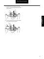
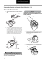
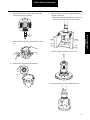
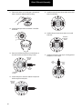
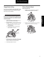
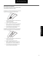
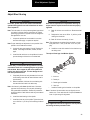
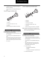
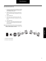
Spicer Single Drive Axles
®
Service Manual
AXSM0055
April 2011
S110 Series
S130 Series
General Information
General Information
The description and specifications contained in this service
publication are current at the time of printing.
Dana reserves the right to discontinue or to modify its
models and/or procedures and to change specifications
at any time without notice.
Any reference to brand name in this publication is made simply as an example of the types of tools and materials recommended for use and should not be considered an
endorsement. Equivalents, if available, may be used.
Important Notice
This symbol is used throughout this
manual to call attention to procedures
where carelessness or failure to follow
specific instructions may result in
personal injury and/or component
damage.
CAUTION: Failure to follow indicated
procedures may cause component
damage or malfunction.
IMPORTANT: Highly recommended
procedures for proper service of this unit.
General Information
Departure from the instructions, choice
of tools, materials and recommended
parts mentioned in this publication
may jeopardize the personal safety
of the service technician or vehicle
operator.
WARNING: Failure to follow indicated
procedures creates a high risk of personal
injury to the servicing technician.
NOTE: Additional service information not
covered in the service procedures.
TIP: Helpful removal and installation
procedures to aid in the service of this unit.
M
OE
Refer to the OEM vehicle specifications
Always use genuine Spicer replacement parts.
i
Table of Contents
General Information .............................................i
Important Notice .......................................................... i
Introduction ........................................................1
Model Listing ..............................................................
Model Information ......................................................
Model Identification ....................................................
Part Identification........................................................
1
1
2
2
Ring Gear and Pinion ..........................................3
Inspection ...........................................................4
Failure Analysis ........................................................... 4
How to Diagnose a Failure........................................... 4
.........................Prepare the Parts for Inspection 5
Find the Cause of the Failure .......................................
Correct the Cause of the Problem ...............................
Inspection ...................................................................
Inspect Axle Housing ..................................................
Inspect Components ...................................................
Inspect Primary Gearing .............................................
5
5
6
6
7
7
Differential Carrier Assembly ..............................8
S110 Carrier Assembly .......................................9
S130 Carrier Assembly .....................................11
Remove Differential Carrier ...............................12
Standard Differentials................................................ 12
Disassemble, Overhaul, and Assemble Wheel
Differential - S110 .............................................21
Disassemble Wheel Differential ................................. 21
Disassemble, Overhaul, and Assemble Wheel Differential - S130 .....................................................26
Disassemble Wheel Differential ................................. 26
Measure and Adjust Carrier Assembly ..............32
Adjust Backlash and Preload ..................................... 32
Change Backlash Setting ........................................... 33
Measure Ring Gear Runout ....................................... 33
Adjust Ring and Pinion Tooth Contact Pattern ..34
Install Axle Housing Breather ............................36
Wheel End Seal - Parts Exploded View .............37
Remove and Overhaul Wheel End Seal .............38
Adjust Wheel Bearing ........................................39
Wheel End .........................................................41
Verify Wheel End-play Procedure .............................. 41
Adjust End-play with Tire and Wheel Assembly ......... 41
Adjust End-play with Wheel Hub................................ 41
Readjust Wheel End-play Procedure.......................... 41
Lubricate Wheel End .........................................42
Lubrication ........................................................44
Approved Lubricants ................................................. 44
Recommendations for Viscosity/Ambient Temp ........ 44
Lube Change Intervals ............................................... 45
Install Differential Carrier ..................................13
Remove Wheel Differential ................................14
Pinion - Parts Exploded View ............................15
Pinion Removal .................................................16
Drive Pinion ......................................................17
Change Lube .....................................................46
Rear Axle Pinion Assembly - Parts Exploded View.... 17
Proper Vehicle Towing ......................................47
Drain.......................................................................... 46
Fill.............................................................................. 46
Pinion Installation .............................................18
With Truetrac Limited Slip Differential ....................... 47
Final Buildup ............................................................. 18
Torque Flow ......................................................48
Torque Chart .....................................................49
Wheel Differential Assembly - Parts Exploded ..20
Introduction
Introduction
Dana Commercial Vehicle Division, presents this publication to aid in maintenance and overhaul of Spicer single drive axles.
Instructions contained cover the models listed. Their design is common, with differences in load capacity. Capacity variations
are achieved by combining basic differential carrier assemblies with different axle housings, axle shafts and wheel equipment.
Model Listing
Load Capacity
S10-110
10,000
S12-110
12,000
S14-110
14,000
S16-130
16,000
Introduction
Rear Axle
Model Information
S 14 - 1 1 0 L
S - Single Rear Axle
GAW Rating x 1000 lbs.
Gear Type
1 - Standard Single Reduction
2 - Dual Range
3 - Planetary Double Reduction
4 - Controlled Traction Differential
5 - Helical Reduction
Options
B - Bus Specific
D - Differential Lock
H - Heavy Wall
I - Integral Brake
L - Limited-Slip
R - Retarder/Parking Brake Ready
W - Wide-track
F - Roll Over
Design Level
Head Assembly Series
1
Introduction
Model Identification
Drive Axle
Data plate is located on
the axle centerline
4
5
3
Spicer®
CUST. PART NO.
SPEC.
MODEL PART NO.
SERIAL NO.
RATIO
MADE IN:
2
6
1
7
Rear Axle (Front View)
1 - Country of origin
2 - Axle model identification
3 - Specification number assigned to the axle built by Spicer.
Identifies all component parts of the axle including special
special OEM requirements such as yokes or flanges.
4 - OEM part number assigned to the axle build
5 - Carrier assembly serial number assigned by the
manufacturing plant
6 - Axle gear ratio
7 - Carrier assembly production or service part number
Part Identification
Axle Housing
Axle Shaft
2
®
erS.
Spic LB
.
NO
PT. CAP.
.
G.
HS I.D. NO DE IN
G.
HS ING MA
US
HO
1 - ID Tag
2
1
2 - Axle shaft part number
Introduction
Ring Gear and Pinion
Note: Ring gear and drive pinion are matched parts and must be replaced in sets.
3
8
38
L70
127381
SPICER
1
7
41-8
4
6
2
5
17
OF
NL2
G
8
7
Introduction
17
SPICER
0H
7
6
12
127
8-41
G
428
127
3
1
JD77
85405
6-39
86
4
1 - Part number
2 - Number of ring gear teeth
3 - Manufacturing numbers
4 - Matching gear set number
5 - Number of pinion teeth
6 - Date code
7 - Indicates genuine Spicer parts
8 - Heat Code
3
General Information
Inspection
Failure Analysis
Failure analysis is the process of determining the original
cause of a component failure in order to keep it from happening again. Too often, when a failed component is replaced
without determining its cause, there will be a recurring failure.
If a carrier housing is opened, revealing a ring gear with a broken tooth, it is not enough to settle on the broken tooth as the
cause of the carrier failure. Other parts of the carrier must be
examined. For a thorough understanding of the failure and
possible insight into related problems, the technician needs to
observe the overall condition of the vehicle.
No one benefits when a failed component goes on the junk
pile with the cause unknown. Nothing is more disturbing to a
customer than a repeat failure. Systematically analyzing a failure to prevent a repeat occurrence assures quality service by
avoiding unnecessary downtime and further expense to the
customer.
The true cause of a failure can be better determined by knowing what to look for, determining how a piece of the equipment was running and learning about previous problems. In
the case of a rebuilt rear axle, mismatched gears may have
been installed. The more successful shops prevent repeat
equipment failures by developing good failure analysis practices. Knowing how to diagnose the cause of a premature failure is one of the prerequisites of a good heavy-equipment
technician.
How to Diagnose a Failure
The following five steps are an effective approach to good failure diagnostics.
1.
Document the problem.
2.
Make a preliminary investigation.
3.
Prepare the parts for inspection.
4.
Find the cause of the failure.
5.
Correct the cause of the problem.
Document the Problem
Here are some guidelines for starting to learn about a failure,
including questions to ask:
4
1.
Talk to the operator of the truck.
2.
Look at the service records.
3.
Find out when the truck was last serviced.
4.
Ask: In what type of service is the truck being used?
5.
Ask: Has this particular failure occurred before?
6.
Ask: How was the truck working prior to the failure?
You need to be a good listener. Sometimes, insignificant or unrelated symptoms can point to the cause of the failure:
7.
Ask: Was the vehicle operating at normal temperatures?
8.
Ask: Were the gauges showing normal ranges of
operation?
9.
Ask: Was there any unusual noise or vibration?
After listening, review the previous repair and maintenance
records. If there is more than one driver, talk to all of them
and compare their observations for consistency with the service and maintenance records. Verify the chassis Vehicle
Identification Number (VIN) number from the vehicle identification plate, as well as the mileage and hours on the vehicle.
Make a Preliminary Investigation
These steps consist of external inspections and observations
that will be valuable when combined with the results of the
parts examination.
1.
Look for leaks, cracks or other damage that can
point to the cause of the failure.
2.
Make note of obvious leaks around plugs and seals.
A missing fill or drain plug would be an obvious
cause for concern.
3.
Look for cracks in the carrier housing (harder to see,
but sometimes visible).
4.
Does the general mechanical condition of the vehicle
indicate proper maintenance or are there signs of
neglect?
5.
Are the tires in good condition and do the sizes
match?
6.
If equipped with a torque-limiting device, is it working properly?
During the preliminary investigation, write down anything out
of the ordinary for later reference. Items that appear insignificant now may take on more importance when the subassemblies are torn down.
Inspection
Prepare the Parts for Inspection
After the preliminary investigation, locate the failure and prepare the part for examination. In carrier failure analysis, it may
be necessary to disassemble the unit.
1.
When disassembling subassemblies and parts, do
not clean the parts immediately since cleaning may
destroy some of the evidence.
2.
When tearing down the drive axle, do it in the recommended manner. Minimize any further damage to the
unit.
3.
Ask more questions when examining the interior of
the carrier. Does the lubricant meet the manufacturer
specifications regarding quality, quantity and viscosity? As soon as you have located the failed part, take
time to analyze the data.
Find the Cause of the Failure
Here begins the real challenge to determine the exact cause of
the failure. Keep in mind that there is no benefit to replacing a
failed part without determining the cause of the failure. For
example, after examining a failed part and finding that the failure is caused by a lack of lubrication, you must determine if
there was an external leak. Obviously, if there is an external
leak, just replacing the failed gear is not going to correct the
situation.
Another important consideration is to determine the specific
type of failure which can be a valuable indicator for the cause
of failure. The following pages show different types of failures
and possible causes. Use this as a guide in determining types
of failures and in correcting problems.
Correct the Cause of the Problem
Once the cause of the problem has been determined, refer to
the appropriate service manual to perform the repairs.
Inspection
5
Inspection
Inspection
Inspect Axle Housing
Clean
1.
Wash steel parts with ground or polished surfaces in
solvent. There are many suitable commercial solvents available. Kerosene and diesel fuel are acceptable.
WARNING
Axle housing inspection and repairs are limited to the following checks or repairs.
•
Visually inspect axle housing for cracks, nicks and
burrs on machined surfaces.
•
Check carrier bolt holes and studs for foreign material.
•
Replace damaged fasteners. Look for loose bolts or
cross-threaded holes
Gasoline is not an acceptable solvent because of its
extreme combustibility. It is unsafe in the workshop environment.
2.
Wash castings or other rough parts in solvent or
clean in hot solution tanks using mild alkali solutions.
Note: If a hot solution tank is used, make sure parts are
heated thoroughly before rinsing.
3.
Rinse thoroughly to remove all traces of the cleaning
solution.
4.
Dry parts immediately with clean rags.
5.
Oil parts.
•
If parts are to be reused immediately: Lightly oil.
•
If parts are to be stored: Coat with oil, wrap in corrosion resistant paper and store in a clean, dry place.
CAUTION
Any damage which affects the alignment or structural integrity of the housing requires housing replacement. Do not
repair by bending or straightening. This process can affect
the material’s properties and cause it to fail completely
under load.
•
Check all seals and gaskets.
Note: Replace conventional gaskets with silicone rubber gasket compound (included in many repair kits). The compound provides a more effective seal against lube
seepage and is easier to remove from mating surfaces
when replacing parts.
1
2
1 - Axle housing
2 - Machined surface
6
Inspection
Inspect Components
Inspect all steel parts for:
•
Notches, visible steps or grooves created by wear.
•
Pitting or cracking along gear contact lines.
•
Scuffing, deformation or discolorations. These are
signs of excessive heat in the axle and are usually
related to low lubrication levels or improper lubrication practices.
In addition, inspect the following for damage:
Differential gearing
•
Bearings for loose fit on drive pinion, and differential
bearings.
•
All fasteners for rounded heads, bends, cracks or
damaged threads.
•
Inspect machined surfaces of cast or malleable
parts. They must be free of nicks, burrs, cracks,
scoring, and wear.
•
Look for elongation of drilled holes, wear on surfaces machined for bearing fits and nicks or burrs in
mating surfaces.
Inspection
•
Inspect Primary Gearing
Before reusing a primary gear set, inspect teeth for signs of
excessive wear. Check tooth contact pattern for evidence of
incorrect adjustment.
7
Differential Carrier Assembly
Differential Carrier Assembly
1
1 - Carrier fastener
2 - Carrier assembly
8
2
Carrier Assembly
S110 Carrier Assembly
21
15
23
12
13
22
14
Carrier Assembly
25
10D
24
20
19
11
18
10C
10B
10, 10A
(10A includes items 10B, 10C and 10D)
31
26 17
9
8
16
7
27
6
28
5
29
4
30
3
32
(Optional Truetrac)
2
1
9
Carrier Assembly
1 - Pinion Nut
2 - End Yoke
3 - Slinger
4 - Outer Pinion Bearing Cone
5 - Outer Pinion Bearing Cup
6 - Pinion Spacer
7 - Inner Pinion Bearing Cup
8 - Inner Pinion Bearing Cone
9 - Drive Pinion
10 - Carrier Housing
10A - Carrier Housing Assembly
10B - Switch
10C - Capscrew
10D - Backing Ring
11 - Ring Gear
12 - Ring Gear Bolt
13 - Ring Gear Bearing Cone
14 - Ring Gear Bearing Cup
10
15 - Ring Gear Bearing Adjuster
16 - Side Pinion Thrust Washer
17 - Side Pinion
18 - Side Gear
19 - Differential Shaft
20 - Pin
21 - Capscrew
22 - Flat Washer
23 - Flanged Half Cap
24 - Plain Half Cap
25 - Cotter Pin
26 - Side Gear Thrust Washer
27 - Differential Case
28 - Differential Case Bearing Cone
29 - Differential Bearing Cup
30 - Differential Case Bearing Adjuster
31 - Pipe Plug
32 - Optional Truetrac
Carrier Assembly
S130 Carrier Assembly
23
22
24
26
25
20B
19
20A
14
13
10D (Optional)
12
10B (Optional)
32
21
27
31
30
29
28
18
17
10C (Optional)
9
10, 10A (Optional)
(10A includes items 10B, 10C and 10D)
8
7
6
5
4
3
2
1
1 - Pinion Nut
2 - End Yoke
3 - Slinger
4 - Outer Pinion Bearing Cone
5 - Outer Pinion Bearing Cup
6 - Pinion Spacer
7 - Inner Pinion Bearing Cup
8 - Inner Pinion Bearing Cone
9 - Drive Pinion
10 - Carrier Housing
10A - Carrier Housing Assembly
10B - Switch
10C - Capscrew
10D - Backing Ring
11 - Diff Case Dowels
12 - Ring Gear
13 - Ring Gear Bolt
14 - Flange Half Bearing Cone
15 - Flange Half Bearing Cup
16 - Fland Half Bearing Adjuster
17 - Side Pinion Thrust Washer
18 - Side Pinion
19 - Side Gear
20A - Differential Shaft
20B - Differential Stub Shaft
21 - Pin
22 - Capscrew
23 - Flat Washer
24 - Flange Half Cap
25 - Plain Half Cap
26 - Cotter Pin
27 - Side Gear Thrust Washer
28 - Plain Half Diff Case
29 - Plain Half Bearing Cone
30 - Plain Half Bearing Cup
31 - Plain Half Bearing Adjuster
32 - Pipe Plug
33 - Optional Truetrac
11
Carrier Assembly
11
15 16
Differential Carrier Assembly
Remove Differential Carrier
Standard Differentials
1.
Block the vehicle.
2.
Drain axle lubricant. Remove bottom two (2) capscrews.
3.
Disconnect driveline.
4.
Remove axle shafts. (If used, remove lock washers
and taper dowels.)
WARNING
WARNING
Do not lie under carrier after fasteners are removed. Use
transmission jack to support differential carrier assembly
prior to loosening fasteners.
CAUTION
Do not strike the shaft head with a steel hammer. Do not
use chisels or wedges to loosen shaft or dowels.
12
5.
Remove carrier capscrews and washers.
6.
Remove differential carrier assembly.
Differential Carrier Assembly
Install Differential Carrier
IMPORTANT
Before installing carrier assembly, inspect and thoroughly
clean interior of axle housing using an appropriate solvent
and clean rag.
1.
Apply Spicer approved RTV compound on axle
housing mating surface as shown in the illustration.
Completely remove all old gasket material prior to
applying new material. Compound will set in 20 minutes. Install carrier before compound sets or reapply.
Differential Carrier
Assembly
1
1 - Apply RTV gasket in this pattern
TIP: To assist in installing complete differential carrier use
two pieces of threaded rod (M14 X 2) threaded into carrier
capscrew holes. Rod should be approximately 4" (102 mm)
long. Use these to pilot the carrier into the housing.
2.
Install carrier to housing, lock washers and capscrews. Torque to proper specification. Torque to
142–158 lbs. ft. (193–214 N•m).
3.
Install axle shafts and axle stud nuts.
4.
Add axle lubricant. Fill to bottom of filler hole in carrier.
5.
Connect main driveline and lubricate joints.
13
Differential Carrier Assembly
Remove Wheel Differential
Note: Omit this step if the gear set is to be replaced. If gear
set is to be reused, check tooth contact pattern and ring
gear backlash before disassembling differential carrier.
When checking backlash, a yoke must be installed and
torqued to get an accurate reading. Best results are
obtained when established wear patterns are maintained
in used gearing.
1.
Punch mark bearing caps. If reusing gear set, also
punch mark bearing adjusters for reference during
assembly.
1
1 - Punch Marks
14
Remove capscrews and bearing caps. Back off bearing adjusters and remove adjusters and bearing
cups.
4.
Lift ring gear and differential assembly out of carrier.
Mount differential carrier in repair stand.
Note: For easier disassembly, loosen but do not remove pinion (self-locking) nut.
2.
3.
Differential Carrier Assembly
Pinion - Parts Exploded View
11
10
9
Differential Carrier
Assembly
8
7
6
5
4
3
2
1 - Pinion Nut
2 - End Yoke
3 - Slinger
4 - Oil Seal
5 - Outer Pinion Bearing Cone
6 - Outer Pinion Bearing Cup
1
7 - Pinion Spacer
8 - Inner Pinion Bearing Cup
9 - Inner Pinion Bearing
10 - Drive Pinion
11 - Carrier
15
Differential Carrier Assembly
Pinion Removal
1.
Remove yoke nut.
2.
Remove yoke using a yoke puller service tool.
6.
Press pinion through outer bearing and out of carrier
casting.
7.
Remove bearing preload spacer and save for use in
reassembly.
8.
Remove inner bearing cone from pinion using a
split-type puller. Use two procedure steps to remove
each bearing.
a.
Mount puller vertically to separate the bearing. This
action will force puller halves under bearing and start
moving bearing off pinion.
b.
Mount puller horizontally to press pinion out of bearing.
1
1 - Yoke puller
3.
Remove oil seal.
4.
Place carrier in a press with threaded end of pinion
face up.
5.
Place a wood block under pinion to avoid damage to
gear teeth.
1
1
3
2
6
5
4
1 - Press
2 - Outer bearing
3 - Inner bearing
4 - Wood block
5 - Drive pinion
6 - Bearing preload spacer
16
1 - Press
9.
If bearings are to be replaced, remove bearing cups
from carrier casting at this time. Pinion removal
complete.
Drive Pinion
Drive Pinion
Drive Pinion
Rear Axle Pinion Assembly - Parts Exploded View
10
9
8
7
6
5
4
3
2
1
1 - Pinion Nut
2 - End Yoke
3 - Slinger
4 - Oil Seal
5 - Outer Pinion Bearing Cone
6 - Outer Pinion Bearing Cup
7 - Pinion Spacer
8 - Inner Pinion Bearing Cup
9 - Inner Pinion Bearing Cone
10 - Drive Pinion
17
Drive Pinion
Pinion Installation
Final Buildup
3.
Press inner and outer bearing cups into the carrier
until seated. Use a feeler gage (.0015" [.038 mm]
approx.) to make sure that bearing cups are fully
seated in bearing bores. Apply lubricant to both cup
and cone.
4.
Place carrier housing in press with the pinion supported by wood block (6" x 6" x 6" [152 x 152 x 152
mm]), so the inner pinion bearing is mated to the
cone.
Note: Do not install oil seal in carrier until bearing preload is
correctly adjusted.
1.
Press inner bearing cone on pinion.
1
2
5
4
3
1 - Press
2 - Outer pinion bearing
IMPORTANT
3 - Wood block
To prevent bearing damage, use suitable sleeve that only
contacts inner race of bearing cone.
2.
18
4 - Drive pinion
Install preselected bearing spacer.
5 - Bearing preload spacer
5.
Press outer bearing onto pinion until completely
seated. Rotate carrier during seating process.
6.
Use torque multiplier and torque pinion nut to
625-753 lbs. ft. (847-1021 N•m).
Drive Pinion
7.
10. Handle the seal by its outside diameter avoiding any
contact with the seal lips. During installation, use the
proper driver to make sure that the seal is mounted
properly.
11. Use a rubber mallet to drive the seal tool in until the
flange bottoms on the housing cover bore face. The
flange will locate the seal at the proper depth.
1
2
3
Note: If bearing preload does not fall within allowed limits,
preload can be increased by using a thinner spacer and
decreased by using a thicker spacer.
Pinion bearing preload spacers are available in the
following thicknesses 27.44-28.00 mm.
Always measure each spacer before assembly to
ensure correct thickness.
8.
Repeat process until torque to rotate is between
20-40 in. lbs. (2.3-4.5 N•m). After proper preload is
achieved, remove yoke and install new seal with
proper service tool.
12. Install end yoke.
Note: Spicer recommends that new torque prevailing
nuts be used.
13. Use torque multiplier and torque pinion nut to
625-753 lbs. ft. (847-1021 N•m).
1 - Seal Driver
2 - Oil Seal
3 - Pinion Cage
CAUTION
Do not use any silicone or permatex-type bore sealant with
this seal.
9.
Remove the new seal from its package and install
with the proper driver:
R-Pinion-Use drive #126917 only
WARNING
Due to the resiliency of the plastic driver, hammer rebound
may occur when the seal is seated. Keep clear of the hammer rebound path!
19
Drive Pinion
Measure torque to rotate the pinion with an inchpound torque wrench. Torque measurements should
be taken every fourth (4th) revolution and should
read between 20-40 in. lbs. (2.3-4.5 N•m) of bearing
preload.
Wheel Differential Assembly
Wheel Differential Assembly - Parts Exploded
9
8
9
10
S130
8
7
6
6
7
8
10
7
5
8
9
13
9
12
16
9
8
10
1
2
3
11
7
6
4
S110
6
5
8
9
1 - Diff. Case Bearing Adjuster
2 - Diff. Bearing Cup
3 - Diff. Case Bearing Cone
4 - Differential Case
5 - Side Gear Thrust Washer
6 - Side Gear
7 - Differential Shaft
8 - Side Pinion
20
9 - Side Pinion Thrust Washer
10 - Pin
11 - Ring Gear
12 - Ring Gear Bolt
13 - Ring Gear Bearing Cone
14 - Ring Gear Bearing Cup
15 - Ring Gear Bearing Adjuster
16 - Locating Dowels
14
15
Wheel Differential Assembly
Disassemble, Overhaul, and Assemble Wheel Differential - S110
Disassemble Wheel Differential
1.
Remove capscrews fastening ring gear to differential
case.
CAUTION
The differential case and gears will fall after separation.
Support the case so that it will not cause damage to the differential or bodily injury.
Lift out outer side gear.
4.
Remove differential shaft locking pin with pliers.
Wheel Differential
Assembly
3.
2.
The ring gear to differential case interface is a press
fit. Place the assembly in a press with the case facing downward. Support the assembly on either side
of the ring gear. Thread a capscrew back into one of
the case holes by hand. Press down on the head of
the capscrew, you may need to press in more than
one position to free the ring gear from the case.
1
1 - Locking pin
5.
Remove shaft, side pinions and thrust washers.
IMPORTANT
Do not press on the wheel differential shaft to free the ring
gear from the case. Pressing on the wheel differential shaft
may cause it to bend and/or fatigue.
21
Wheel Differential Assembly
22
6.
Remove inner side gear and thrust washer.
7.
Remove bearing cones from ring gear and differential case in two steps:
a.
Mount puller vertically to split bearing. This action
will start moving bearing off case and gear.
b.
Mount puller horizontally to remove cone.
8.
Press new bearing cone on differential case.
9.
Place thrust washer on side gear. Lubricate both
sides of the thrust washer. Install on side gear.
Wheel Differential Assembly
10. Install inner side gear and thrust washer in differential case.
14. Make certain the hole in the shaft and case line up
and install the locking pin.
15. Install outer side gear.
Wheel Differential
Assembly
Note: No thrust washer is used at this location.
11. Start wheel differential shaft in differential case with
the locking pin hole facing up.
12. Install the first side pinion thrust washer and gear.
Push shaft through washer and side pinion.
16. Lower ring gear onto case assembly aligning the ring
gear capscrew holes.
13. Install second side pinion and thrust washer. Push
shaft through washer and side pinion until it is flush
to the outside of the case.
1
23
Wheel Differential Assembly
17. Install and hand-tighten all new ring gear capscrews.
19. Press new ring gear bearing cone.
18. The interface of the ring gear to differential case is a
press fit. Put the assembly in a press with the ring
gear facing upward. Make certain that the ring gear
is flush and square to the differential case before
pressing. Press until ring gear bottoms out on the
case.
IMPORTANT
IMPORTANT
DO NOT use the capscrews to draw the ring gear into place.
Only use a press.
When pressing differential case bearing cones, note that
the bearing is beyond flush with the top of the case. The
cone must be fully seated. To prevent bearing damage, use
suitable sleeve that only contacts the inner race of the
cone. A used bearing race would be a suitable tool. This
tool should have a slit cut if the ID is the same as the bearing boss OD.
20. Tighten and torque ring gear capscrews in an alternating pattern. 140-160 lbs. ft. (190-217 N•m).
24
Wheel Differential Assembly
21. Install differential case assembly into carrier. Be
careful not to damage the differential bearings lowering the assembly.
Wheel Differential
Assembly
22. Lubricate the differential bearings and install bearing
cups and differential bearing adjusters.
25
Wheel Differential Assembly
Disassemble, Overhaul, and Assemble Wheel Differential - S130
Disassemble Wheel Differential
1.
2.
Remove capscrews fastening ring gear to differential
case.
The ring gear to differential case interface is a press
fit. Place the assembly in a press with the case facing downward. Support the assembly on eitiher side
of the ring gear. Thread a capscrew back into one of
the case holes by hand. Press down on the head of
the capscrew, you may need to press in more than
one position to free the ring gear from the case.
IMPORTANT
Do not press on the wheel differential shaft to free the ring
gear from the case. Pressing on the wheel differential shaft
may cause it to bend and/or fatigue.
26
CAUTION
The differential case and gears will fall after separation.
Support the case so that it will not cause damage to the differential or bodily injury.
3.
Remove the outer side gear.
4.
Remove the differential shaft locking pins by turning
the differential case opening facing down. Use a
hammer to lightly tap on the side of the case to free
the locking pins.
5.
The locking pins are slip fit and should fall from the
case easily.
Wheel Differential Assembly
6.
Remove the half shafts first and then remove their
side pinions and thrust washers.
9.
Remove bearing cones from ring gear and differential case in two steps:
A. Mount puller vertically to split bearing. This action
will start moving the bearing off case and gear.
7.
Wheel Differential
Assembly
Half
Differential
Shaft
Remove the full shaft, side pinions and thrust washers.
B. Mount puller horizontally to remove cone.
8.
Remove inner side gear and thrust washer.
10. Press new bearing cone on the differential case.
27
Wheel Differential Assembly
11. Place thrust washer on the side gear. Lubricate both
sides of the thrust washer before installing.
15. Install the side pinion and thrust washer to the other
side of the full shaft.
12. Install the side gear and thrust washer in the differential case.
16. Install a side pinion and thrust washer on the half
shaft side.
Side Pinion
and Thrust
Washer
13. Start the full differential shaft into the shaft bores in
the case that does not have a locking pin hole.
17. Install the half shaft so that the pin is facing upward
and push it in until it stops.
Side Pinion
and Thrust
Washer
Half
Differential
Shaft
Full
Differential
Shaft
Locking
Pin Holes
14. Install a side pinion and thrust washer and push the
shaft through the side pinion.
Side Pinion
and Thrust
Washer
28
Pin Hole
Facing
Upward
Wheel Differential Assembly
18. The end of the half shaft should fit into the slot of
the full shaft at the same time as the hole in the case
lines up with the hole in the half shaft.
Align Pin
Holes
21. Next, the two locating dowel pins that are pressed
into the ring gear must be removed.
Note: The dowel can only be pressed in one direction. Press
the dowels towards the inside of the gear.
Fit End
Into Slot
Wheel Differential
Assembly
19. Install the locking pins to both sides of the differential case.
Locking
Pin
22. Press the dowel pins into the holes that the shaft
locking pins were installed.
20. Install outer side gear.
Note: No thrust washer is used at this location.
23. Lower the ring gear onto the case assembly aligning
the locking dowels.
29
Wheel Differential Assembly
24. Install and hand-tighten all new ring gear capscrews.
25. The interface of the ring gear to differential case is a
press fit. Put the assembly in a press with the ring
gear facing upward. Make certain that the ring gear
is flush and square to the differential case before
pressing. Press until ring gear bottoms out on the
case.
IMPORTANT
DO NOT use the capscrews to draw the ring gear into place.
Only use a press.
26. Press new ring gear bearing cone.
IMPORTANT
When pressing differential case bearing cones, note that
the bearing is beyond flush with the top of the case. The
cone must be fully seated. To prevent bearing damage, use
suitable sleeve that only contacts the inner race of the
cone. A used bearing race would be a suitable tool. This
tool should have a slit cut if the ID is the same as the bearing boss OD.
27. Tighten and torque ring gear capscrews in an alternating pattern. See the "Torque Chart" on page 50
for torque specifications.
30
Wheel Differential Assembly
28. Install differential case assembly into carrier. Be
careful not to damage the differential bearings lowering the assembly.
Wheel Differential
Assembly
29. Lubricate the differential bearings and install bearing
cups and differential bearing adjusters.
31
Wheel Differential Assembly
Measure and Adjust Carrier Assembly
Adjust Backlash and Preload
1.
Turn the flange half-bearing adjuster in until the ring
gear contacts the pinion (zero backlash) then back
the adjuster out two (2) notches from the adjuster
lugs.
2
1
1 - Flange half
2 - Plain half
2.
Tighten the plain half-adjuster until the bearing cup
just starts to turn, this is a zero bearing preload.
3.
Tighten the plain half-adjuster two lug notches. Start
with the notch at the top, count two notches counterclockwise on the adjuster, turn the adjuster so
that the notch is facing straight up. You now have a
two-notch preload.
2
1
1 - Lugs
2 - One notch
32
4.
Use a rubber mallet to make certain that both bearing adjusters are fully seated.
5.
Measure backlash. Make sure it is within specification of .006"–.018” (.15-.46 mm).
TIP: To give yourself room to adjust contact pattern, set it
between .012"–.014” (.30-.36 mm).
Wheel Differential Assembly
Change Backlash Setting
If you have too much backlash, the ring gear needs to move
closer to the pinion. Back off the plain half-adjuster, counting
the number of notches you back it off (each notch equals
about .003" [.08 mm] of backlash).
Measure Ring Gear Runout
Measure Ring Gear Total
1.
Measure ring gear total radial runout. (Indicator
reading should not exceed .010" [.25 mm]).
2.
Measure ring gear total backface runout. (Indicator
reading should not exceed .010" [.25 mm]).
IMPORTANT
1.
Install carrier bearing caps and torque carrier cap
bolts to 130–150 lbs. ft. (176-203 N•m).
2.
Recheck backlash: If the bearing adjusters were not
in straight or fully seated, the backlash will change.
a.
Used Gearing: Reset to backlash recorded
before disassembly.
b.
New Gearing: Backlash should be between
.006” and .018" (.15-.46 mm).
3.
Check ring gear tooth contact pattern. Paint ring gear
teeth and check tooth contact pattern. Correct tooth
patterns, see "Adjust Tooth Contact Pattern."
4.
Install bearing adjuster cotter pins.
33
Wheel Differential
Assembly
In order to maintain the differential bearing preload, you
will need to turn the flange half-bearing adjuster the same
amount in the same direction. If you need more backlash,
reverse this procedure.
Adjust Tooth Contact Pattern
Adjust Ring and Pinion Tooth Contact Pattern
Used Gearing - Correct Pattern
2
1
•
Used gearing will not usually display the square,
even contact pattern found in new gear sets. The
gear will normally have a “pocket” at the heal end of
the gear tooth. The more use a gear has had, the
more the line becomes the dominant characteristic
of the pattern.
•
Adjust used gear sets to display the same contact
pattern observed before disassembly. A correct pattern is up off the toe and centers evenly along the
face width between the top land and root. Otherwise,
the length and shape of the pattern are highly variable and is considered acceptable as long as it does
not run off the tooth at any point.
3
4
5
6
1 - Face width
2 - Tooth depth
3 - Heel
4 - Top land
5 - Root
6 - Toe
1.
Identify if new or used gearing.
2.
Check tooth contact pattern (new or used gearing).
New Gearing - Correct Pattern
•
•
34
Paint six ring gear teeth 180° apart and roll the gear
to obtain a contact pattern. The correct pattern is
slightly below center on the ring gear tooth with
lengthwise contact up off the toe. The length of the
pattern in an unloaded condition is approximately
one-half (1/2) to two-thirds
(2/3) of the ring gear tooth in most models and
ratios.
The pattern could vary in length and should cover
half (1/2) of the tooth or more (face width). The pattern should be evenly centered between tooth top
land and root and should be up off the tooth toe.
1 - Pattern along the face width could be longer
Adjust Contact Pattern
•
If necessary, adjust the contact pattern by changing
the ring gear position.
•
Ring gear position controls the backlash. This
adjustment moves the contact pattern along the face
width of the gear tooth.
Note: This is a shimless pinion designed carrier. If the pattern
shows an incorrect pinion cone position, check to make
sure the inner pinion cup is fully seated. Use a feeler
gauge.
Adjust Tooth Contact Pattern
Adjust Ring Gear Position (Backlash)
If the ring gear pattern shows incorrect face width contact,
change backlash by adjusting the ring gear.
If the pattern is too close to the edge of the tooth toe, move the
ring gear away from the pinion to increase backlash.
Loosen the bearing adjuster on the teeth side of the
ring gear several notches.
2.
Loosen the opposite adjuster one notch.
3.
Return to adjuster on teeth side of the ring gear and
tighten adjuster until it contacts the bearing cup.
4.
Continue tightening the same adjuster two (2) or
three (3) notches and recheck backlash.
Adjust Tooth Contact
Pattern
1.
If the pattern is concentrated at the heel (too far up the tooth),
move the ring gear toward the pinion to decrease backlash.
5.
Loosen the bearing adjuster on the teeth side of the
ring gear several notches.
6.
Tighten the opposite adjuster one notch.
7.
Return to adjuster on teeth side of ring gear and
tighten adjuster until it contacts the bearing cup.
8.
Continue tightening the same adjuster two (2) or
three (3) notches and recheck backlash.
35
Housing Breather
Install Axle Housing Breather
1.
Install fitting in breather hole.
2.
Tighten fitting finger tight.
3.
36
Torque to 5 lbs. ft. (7 N•m) and align the nose of the
breather to the rear.
4.
Insert hose onto fitting, long end down.
5.
Push hose firmly against fitting. Rotate hose to point
down.
Wheel End Seal
Wheel End Seal
Wheel End Seal - Parts Exploded View
1
2
3
1 - Installation tool
2 - Seal
3 - Rear hub
37
Wheel End Seal
Remove and Overhaul Wheel End Seal
Install Wheel End Seal
WARNING
1.
Never work under a vehicle supported by only a jack.
Always support vehicle with stands. Block the wheels and
make sure the vehicle will not roll before releasing the
brakes.
IMPORTANT
Wheel end seals can be easily damaged during handling.
Leave the seal in its package until installation to prevent
damage or contamination.
1.
Remove outer nut and locking washer.
2.
Remove inner nut.
3.
Remove outer bearing and wheel.
4.
Remove oil seal.
5.
Remove inner bearing.
6.
Inspect spindle journal and hub bore for scratches or
burrs. Recondition with an emery cloth as required.
Note: Deep gouges can be repaired by filling gouge with hardening gasket cement and smoothing with emery cloth.
7.
Clean hub cavity and bearing bores before reassembly. Be sure to remove contaminants from all
recesses and corners.
8.
Clean bearings thoroughly with solvent and examine
for damage. Replace damaged or worn bearings.
IMPORTANT
Always use the seal installation tool specified by the seal
manufacturer. Using an improper tool can distort or damage the seal and cause premature seal failure.
38
Before installation, lubricate the following with the
same lubricant used in the axle sump.
•
Inner bearing.
•
Wheel seal (follow the directions provided by
the seal supplier).
2.
Place seal on installation tool.
3.
Drive seal with installation tool onto hub.
Wheel Adjustment Systems
Adjust Wheel Bearing
WARNING
Do not mix spindle nuts and lock washers from different
systems. Mixing spindle nuts and lock washers can cause
wheel separation.
1.
Inspect the spindle and nut threads for corrosion
and clean thoroughly or replace as required.
Note: Proper assembly and adjustment is not possible if the
spindle or nut threads are corroded.
2.
Inspect the tang-type washer (if used). Replace the
washer if the tangs are broken, cracked, or damaged.
3.
Install the hub and drum on the spindle with care to
prevent damage or distortion to the wheel seal.
Never use an impact wrench to adjust wheel bearings. A
torque wrench is required to assure the nuts are properly
tightened.
8.
Back off the inner nut one full turn. Rotate the wheel
hub.
9.
Retighten the inner nut to 50 lbs. ft. (68 N•m) while
rotating the wheel hub.
10. Back off the inner nut exactly 1/4 turn.
Note: This adjustment procedure allows the wheel to rotate
freely with 0.001" -.005” (0.025 mm–0.127 mm) endplay.
11. Install the correct lock washer for the wheel nut system being used.
Three-piece Dowel-type Lock Washer System
CAUTION
A wheel dolly is recommended during installation to make
sure that the wheel seal is not damaged by the weight of the
hub and drum. Never support the hub on the spindle with
just the inner bearing and seal. This can damage the seal
and cause premature failure.
4.
5.
2
1
3
4
Completely fill the hub cavity between the inner and
outer bearing races with the same lubricant used in
the axle sump.
1 - Inner nut
Before installation, lubricate the outer bearing with
the same lubricant used in the axle sump.
3 - Dowel-type lock washer
Note: Lubricate only with clean axle lubricant of the same
type used in the axle sump. Do not pack the bearings
with grease before installation. Grease will prevent the
proper circulation of axle lubricant and may cause wheel
seal failure.
6.
Install the outer bearing on the spindle.
7.
Install the inner nut on the spindle. Tighten the inner
nut to 200 lbs. ft. (271 N•m) while rotating the wheel
hub.
2 - Dowel pin
4 - Outer nut
•
Install the Dowel-type lock washer on the spindle.
Note: If the dowel pin and washer are not aligned, remove
washer, turn it over and reinstall. If required, loosen the
inner nut just enough for alignment.
IMPORTANT
Never tighten the inner nut for alignment. This can preload
the bearing and cause premature failure.
39
Wheel Adjustment
Systems
Note: The lock washer for a four-piece tang/dowel-type wheel
nut system is thinner than the lock washer for a threepiece tang-type wheel nut system and is not designed to
bear against the inner nut.
CAUTION
Wheel Adjustment Systems
•
Install the outer nut on the spindle and tighten to
350 lbs. ft. (475 N•m).
•
Verify end-play, see “Verify Wheel End Play Procedure."
Four-piece Tang/Dowel-type Lock Washer System
Three-piece Tang-type Lock Washer System
3
4
5
2
1
1
2
1 - Inner nut
3
2 - Dowel pin
•
1 - Inner nut
3 - Dowel-type lock washer
2 - Tang-type lock washer .123” thick
4 - Tang-type lock washer .0478” thick
3 - Outer nut
5 - Outer nut
Install the Tang-type lock washer on the spindle.
IMPORTANT
•
Install the Dowel-type lock washer on the spindle.
Note: If the dowel pin and washer are not aligned, remove
washer, turn it over and reinstall. If required, loosen the
inner nut just enough for alignment.
Never tighten the inner nut for alignment. This can preload
the bearing and cause premature failure.
•
Install the outer nut on the spindle and tighten to 250
lbs. ft. (339 N•m).
•
Verify end-play, see “Verify Wheel End Play Procedure."
•
After verifying end-play, secure wheel nuts by bending one of the locking washer tangs over the outer
wheel nut and another tang over the inner wheel nut.
•
Go to step 12.
IMPORTANT
Never tighten the inner nut for alignment. This can preload
the bearing and cause premature failure.
•
Install the Tang-type lock washer on the spindle.
•
Install the outer nut on the spindle and tighten to 250
lbs. ft. (339 N•m).
•
Verify end-play, see “Verify Wheel End Play Procedure."
•
After verifying end-play, secure the outer nut by
bending (180° apart) two opposing tangs of the
locking washer over the outer nut.
12. Install the following:
•
New gasket at axle shaft flange.
•
Axle shaft.
•
Axle flange nuts and tighten to specified torque.
13. Lubricate axle wheel ends.
40
Wheel Adjustment
Wheel End
Verify Wheel End-play Procedure
Adjust End-play with Wheel Hub
Verify end-play meets specification using a dial indicator. An
indicator with .001" (.03 mm) resolution is required. Wheel
end-play is the free movement of the tire and wheel assembly
along the spindle axis.
Correct end-play is .001-.005” (.025-.125 mm).
1.
Attach a dial indicator with its magnetic base to the
hub or brake drum as shown below.
2.
Adjust the dial indicator so that its plunger or pointer
is against the end of the spindle with its line of action
approximately parallel to the axis of the spindle.
3.
Grasp the wheel assembly at the 3 o’clock and
9 o’clock positions. Push the wheel assembly in and
out while oscillating it to seat the bearings. Read
bearing end-play as the total indicator movement.
CAUTION
Adjust End-play with Tire and Wheel Assembly
Readjust Wheel End-play Procedure
Excessive End-play: If end-play is greater than .005"
(.127 mm), remove the outer nut and pull the lock washer
away from the inner nut, but not off the spindle. Tighten the
inner nut to the next alignment hole of the dowel-type washer
(if used). Reassemble the washer and retorque the outer nut.
Verify end-play with a dial indicator.
Insufficient End-play: If end-play is not present, remove the
outer nut and pull the lock washer away from the inner nut,
but not off the spindle. Loosen the inner nut to the next
adjustment hole of the dowel-type washer (if used). Reassemble the washer and retorque the outer nut. Verify end-play
with a dial indicator.
Fine Tuning the End-play: If, after performing the readjustment procedures, end-play is still not within the .001"-.005”
(.025-127 mm) range, disassemble and inspect the components. If parts are found to be defective, replace the defective
parts, reassemble and repeat wheel bearing adjustment procedure. Verify end-play with a dial indicator.
41
Wheel End
If end-play is not within specification, readjustment is
required.
With indicator mounted at bottom, push / pull at sides of
drum.
Wheel Adjustment
Lubricate Wheel End
IMPORTANT
Before operating the axle, the wheel hub cavities and bearings must be lubricated to prevent failure.
Wheel End with Oil Fill Hole
1
When wheel ends are serviced, follow Spicer’s wheel
end lubrication procedure before operating the axle.
Spicer axles may be equipped with either of two (2)
wheel-end designs:
•
Wheel ends with an oil fill hole.
•
Wheel ends without an oil fill hole .
2
Wheel Ends with an Oil Fill Hole
1.
Remove the oil fill plug.
2.
Pour half (1/2) a pint of axle sump lubricant into
each hub through the wheel end fill hole.
3.
Install oil fill plug and tighten to specified torque.
1 - Wheel end oil fill hole
2 - Proper lubricant level
Wheel End without Oil Fill Hole
1
1 - Lubricant flow from sump
42
Wheel Adjustment
Wheel Ends without Oil Fill Hole
1.
With axle level and wheel ends assembled, add lubricant through filler hole in carrier until fluid is level
with the bottom of filler hole.
2.
Raise the right side of the axle six (6) inches (152
mm) or more. Hold axle in this position for one (1)
minute.
3.
Lower the right side.
4.
Raise the left side of the axle six (6) inches (152
mm) or more. Hold axle in this position for one (1)
minute.
5.
Lower the left side.
6.
With axle on a level surface, add lubricant through
carrier oil filler hole until fluid is level with the bottom of the hole.
Note: Axles without wheel end fill holes will require approximately 2.5 additional pints of lubricant to bring the lube
level even with the bottom of fill hole.
2
Wheel End
1
1 - Oil will run into wheel end
2 - Oil will run into wheel end
43
Lubrication
Lubrication
The ability of a drive axle to deliver quiet, trouble-free operation over a period of years is largely dependent upon the use
of good-quality gear lubrication in the correct quantity. The
most satisfactory results can be obtained by following the
directions contained in this manual.
The following lubrication instructions represent the most current recommendations from Dana.
Approved Lubricants
General - Gear lubrications acceptable under military specification (MILSPEC) MIL-L-2105D (Lubricating Oils, Gear, Multipurpose) are approved for use in Spicer Drive Axles.
The MIL-L-2105D specification defines performance and viscosity requirements for multigrade oils. It supersedes both
MIL-L-2105B, MIL-L-2105C and cold weather specification
MIL-L-10324A. This specification applies to both petroleumbased and synthetic based gear lubricants if they appear on
the most current “Qualified Products List” (QPL-2105) for
MIL-L-2105D.
Note: The use of separate oil additives and/or friction modifiers are not approved in Spicer Drive Axles.
Synthetic Based - Synthetic-based gear lubricants exhibit
superior thermal and oxidation stability, and generally
degrade at a lower rate when compared to petroleum-based
lubricants. The performance characteristics of these lubricants include extended change intervals, improved fuel economy, better extreme temperature operation, reduced wear and
cleaner component appearance. The family of Spicer gear
lubricants represents a premium quality synthetic lube
which fully meets or exceeds the requirements of
MIL-L-2105D. These products, available in both 75W-90
and 80/W-140, have demonstrated superior performance in
comparison to others qualified under the MILSPEC, as demonstrated by extensive laboratory and field testing. For a complete list of Spicer-approved synthetic lubricants, contact
your local Dana representative. See back cover of this manual
for appropriate phone number.
Makeup Lube - Maximum amount of non-synthetic makeup
lube is 10%.
44
Recommendations for Viscosity/Ambient
Temperature
The following chart lists the various SAE Grades covered by
MIL-L-2105D and the associated ambient temperature range
from each. Those SAE grades shown with an asterisk (*) are
available in the Spicer family of synthetic gear lubricants.
The lowest ambient temperatures covered by this chart are
-40°F and -40°C. Lubrication recommendations for those
applications which consistently operate below this temperature range must be obtained through Dana by contacting
your local Dana representative.
Grade
Ambient Temperature Range
75W
-40°F to -15°F (-40°C to -26°C)
75W-80
-40°F to 80°F (-40°C to 21°C)
75W-90*
-40°F to 100°F (-40°C to 38°C)
75W-140
-40°F and above (-40°C and above)
80W-90
-15°F to 100°F (-26°C to 38°C)
80W-140*
-15°F and above (-26°C and above)
85W-140
10°F and above (-12°C and above)
* Available in the Spicer family of synthetic gear lubricants.
Lubrication
Lube Change Intervals
Change the lubricant within the first 5,000 miles of operation when not using a Spicer-approved synthetic lubricant
in either a new axle or after a carrier head replacement.
Base subsequent lubricant changes on a combination of
the following chart and user assessment of the application
and operating environment.
Severe Service Lubrication Change Intervals - Severe service applications are those where the vehicle consistently
operates at or near its maximum GCW or GVW ratings, dusty
or wet environments, or consistent operation on grades
greater than 8%. For these applications, the ON/OFF HIGHWAY portion of the chart should be used. Typical applications
are construction, logging, mining and refuse removal.
Note: Clean metallic particles from the magnetic filler plug
and drain plugs. Clean or replace the breather yearly to
avoid lube contamination due to water ingestion.
Synthetic or Lubricant
Mineral
SAE
Change Interval for Line Haul
Change Interval for Vocational
Synthetic*
SHAES-256
SAE 75W-90
500,000 miles [800,000 Km] or
5 years
120,000 miles (193,000 Km)
or 1year
Synthetic**
SHAES-256
SAE 75W-90,
75W-140
250,000 miles (400,000 Km) or
3 years
60,000 miles [96,500 Km] or 1
year
Mineral
Base
MIL-L-2105E/J02360,
API GL-5 Gear Oil,
MIL-PRF-2105E
75W, 75W-90,
75W-140, 80W90, 85W-140
120,000 miles [193,000 Km] or
1 year
60,000 miles [96,500 Km] or
1 year
* Axles using LMS wheel end system
** Axles using adjustable wheel bearing system
45
Lubrication
This product combines the latest manufacturing and part
washing technology. When filled with a Spicer-approved
synthetic lubricant at the factory, the initial drain is
not required.
Lubrication
Change Lube
Drain
Fill
1.
Drain when the lube is at normal operating temperature (150°-200°F [66°-93°C]). It will run freely and
minimize the time necessary to fully drain the axle,
this insures the axle is flushed.
2.
Remove the bottom two carrier to housing capscrews and allow the lube to drain into a suitable
container.
Note: Dispose of all used lubricants properly by following disposal methods approved for mineral- or synthetic-based
oils.
3.
Inspect breather for clogging or corrosion. Clean or
replace as necessary.
1.
Reinstall bottom two carrier to housing capscrews –
use Loctite 270 and torque to 142–158 lbs. ft. (193214 N•m).
2.
Remove the filler hole plug from the side of the carrier and fill the axle with the approved lubricant until
level with the bottom of the hole.
3.
If wheel ends were removed, follow instructions in
the wheel end servicing section.
Always use the filler hole as the final reference. If lube is level
with the bottom of the hole, the axle is properly filled.
Note: Lube fill capacities are basic guidelines and will vary
based on the angle the axle is installed in a particular
chassis. Torque fill plug to 40–60 lbs. ft. (54–82 N•m).
TIP: The axle can be filled through the axle housing breather
hole. Fill until lube level is even with the bottom of filler hole in
side of carrier.
46
Proper Vehicle Towing
Proper Vehicle Towing
Lift the drive wheels completely off of the ground or damage
will occur.
WARNING
Proper Vehicle Towing
Do not lift the front wheels (non-drive wheels). This alters
the oil’s position in the drive axle, draining it away from the
drive pinion and its bearings. If the pinion is rotated under
these conditions for any period of time, bearings will overheat resulting in axle damage or failure.
When the vehicle experiences unequal side to side traction
(for instance on wet, muddy, icy or sand/gravel terrain), the
pinions resist rotation in the case and transfer torque from
one side gear to the other. All mating pinions tend to separate
from each other and from the side gears and they wedge into
their case pockets. This provides a friction force that retards
or prevents the wheel with lesser traction from rotating and
spinning out.
This is impossible to lift the drive wheels, remove all axle
shafts to prevent gear rotation and cap the wheel hubs to prevent loss of lubricant and a possible road hazard. See the following section Proper Vehicle Towing with Wheel Differential
Lock for removal procedure.
With Truetrac Limited Slip Differential
These differentials perform like conventional (open) differentials under normal driving conditions - until traction control is
needed. Then the imbalanced gear forces automatically apply
resistance to the wheel (or axle) with the lesser traction.
Planetary pinion gears are supported in pockets of the case.
Each pinion meshes with its side gear and with a mating pinion of the opposite planetary gear set.
47
Torque Flow
Torque Flow
While driving with equal load on and equal traction under both
drive wheels, the Truetrac differential provides equal torque to
each wheel.
1
1 - Torque flow distribution while operating with
equal loading and ground coefficient
With unequal load and/or traction on each drive wheel, a
major portion of the torque will be transferred from one side
to the other to reduce the chance of a one wheel spin out.
1
1 - Torque flow distribution with less load over or
ground coefficient under left wheel
48
Torque Chart
Torque Chart
Location
Thread Size
Class/Grade
Torque Specification
Pinion Shaft End Nut
M36X1.5
10.9
625-753 lbs. ft. (847-1021 N•m)
Ring Gear to Case Capscrew
M14X2 (S110)
M16X2 (S130)
10.9
10.9
140-160 lbs. ft. (190-217 N•m)
225 +/- 10 lbs. ft. (305 +/-13 N•m)
Carrier Cap Capscrew
M14X2
10.9
130-150 lbs. ft. (176-203 N•m)
Head to Housing Capscrew
M14X2
10.2
140-160 lbs. ft. (190-217 N•m)
ABS Set Screw
.312-18
18-26 lbs. ft. (25-35 N•m)
Torque Chart
49
For spec‘ing or service assistance, call 1-877-777-5360 or visit our website at www.dana.com
Dana Commercial Vehicle Products Group
3939 Technology Drive
Maumee, Ohio, USA 43537
www.dana.com
All applications must be approved by the Application Engineering Department. Specifications and/or design are subject to change without notice or obligation.
Printed in USA
AXSM-0055 04/11