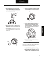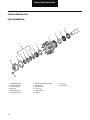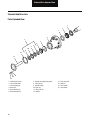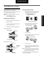
1
Spicer Wheel Ends
®
Service Manual
Steer and Drive Wheel Ends
WESM0060
September 2013
General Information
General Information
The description and specifications contained in this service publication are current at the time of printing.
Dana reserves the right to discontinue or to modify its models and/or procedures and to change specifications at any
time without notice.
Any reference to brand names in this publication is made simply as an example of the types of tools and materials recommended
for use and should not be considered an endorsement. Equivalents, if available, may be used.
Important Notice
This symbol is used throughout this
manual to call attention to procedures
where carelessness or failure to follow
specific instructions may result in
personal injury and/or component
damage.
WARNING
Failure to follow indicated procedures
creates a high risk of personal injury
to the servicing technician.
CAUTION
Failure to follow indicated procedures
may cause component damage or
malfunction.
Departure from the instructions, choice
of tools, materials and recommended
parts mentioned in this publication
may jeopardize the personal safety
of the service technician or vehicle
operator.
IMPORTANT
Highly recommended procedures for
proper service of this unit.
NOTE: Additional service information not
covered in the service procedures.
Always use genuine Spicer replacement parts.
Spicer recommends following all manufacturers recommendations for the proper handling and disposal of lubricants and solvents.
For further information contact the supplier of lubricants and solvents.
CAUTION
Welding or machining on any axle component is prohibited unless noted otherwise in this document or other Spicer
service literature.
Every effort has been made to ensure the accuracy of all information in this guide. However, Spicer makes no expressed
or implied warranty or representation based on the enclosed information.
Table of Contents
Steer Axle Identification....................................................2
Drive Axle Identification....................................................4
Vehicle Application Definitions..........................................6
Drive Axle Shaft to Drive Hub Gasketed
Joint Failure.................................................................7
Wheel End Inspection - Oil Bath........................................8
Wheel End Inspection - Grease Pack................................8
Steer Axle Lubrication Procedure....................................10
Approved Lubricants.......................................................13
Lubrication Change Intervals..........................................15
LMS Steer - Parts Exploded View...................................16
LMS Steer Axle - Removal..............................................17
LMS Wheel End - Assembly............................................19
LMS Stamped Locking Nut System.................................21
LMS Spindle Nut Assembly............................................ 22
Pro-Torq Locking Nut System with LMS..........................23
LMS Wheel End - Verify Wheel End-play.........................25
LMS Wheel End - Lubrication.........................................25
Standard Hub Steer Axles - Lubrication......................... 26
LMS Hub Drive Axle - Parts Exploded View.....................27
LMS Drive Axle - Removal..............................................28
LMS Wheel End - Assembly........................................... 30
LMS Drive Axle Assembly.............................................. 30
LMS Drive Axle Spindle Nut Installation Procedure..........32
LMS Assembly............................................................... 34
Pro-Torq Locking Nut System with LMS......................... 35
LMS Drive Axle - Lubrication..........................................37
Standard Hub Steer Axle - Parts Exploded View............ 38
Standard Hub Steer Axle - Removal................................39
Standard Hub and Spindle Nut - Assembly.................... 40
Pro-Torq Spindle Nut Service..........................................42
Verify Wheel End-play (Standard Axles)......................... 44
Standard Hub Steer Axles - Lubrication......................... 45
Standard Hub Drive Axle - Parts Exploded View............. 46
Standard Hub Drive Axle - Removal................................47
Standard Hub Drive Axle - Assembly............................. 48
Verify Wheel End-play (Standard Axles)......................... 50
Standard Hub Drive Axle - Lubrication............................51
Appendix........................................................................52
General Information
Model Information Identification
Steer Axle Identification
Model Number Information
D Family Numbering System
E Family Numbering System
D -85 0 F
E -120 0 I
Series
GAWR x 100 lbs.
Example:
120 x 100 = 12,000 lbs.
Beam Type
I - I-Beam
T - Tubular Beam
Design Level
Series
Beam Type
F - Standard Width
W - Over 96"
Overall Width
N - Narrow Width
GAWR x 1,000 lbs.
(450 Kg)
Design Level
0 = Standard Axle
I Family Numbering System
I
Beam Type/
Series
2
120 SG
Nominal Load
SG = I-Beam Standard
Carrying Capacity
Overall Width
60 = 6,000 lbs. SB = Coach Beam
80 = 8,000 lbs. W = Over 96"
Overall Width
100 = 10,000 lbs.
120 = 12,000 lbs.
140 = 14,000 lbs.
160 = 16,000 lbs.
180 = 18,000 lbs.
200 = 20,000 lbs.
EFA Family Numbering System
EFA 12 F 4
Series
Nominal Load
Capacity
12 - 12,000 lbs.
18 - 18,000 lbs.
22 - 22,000 lbs.
24 - 24,000 lbs.
Design Level
Beam Type
F - Forged I-Beam
T - Tubular Beam
General Information
General Information
I Family Tag
Model Number Location
The Spicer front non-drive steering axles are identified with a
tag located between the spring pads, on the front side of the
center beam section.
The axle tag contains the serial number, the model number,
and the assembly number.
If Steer Axle is LMS™
, as shown on the hub, see page 30 for
removal and assembly procedures.
If Steer Axle is Standard, see page 39 for removal and
page 21 for assembly procedures.
Tag
1 - Dana Part Number
2 - Serial Number
3 - Model Number
4 - Customer Part Number
5 - Line Set Number
6 - Julian Date
E Family Tag
Dana Part Number
3
General Information
Drive Axle Identification
Model Number Information
S 14 - 1 1 0 L
D S P 40-P
Options
B - Bus Specific
D - Differential Lock
H - Heavy Wall
I - Integral Brake
L - Limited-Slip
R - Retarder/Parking
Brake Ready
W - Wide-Track
S - Single Rear Axle
GAW Rating x 1000 lbs.
Gear Type
1 - Standard Single Reduction
2 - Dual Range
3 - Planetary Double Reduction
4 - Controlled Traction Differential
5 - Helical Reduction
D 46-1 7 0 D
GAW Rating
x 1000 lbs. (N. America) "-"
x 1 Tn. (Europe) "."
Gear Type
1 - Standard Single Reduction
2 - Dual Range
3 - Planetary Double Reduction
4 - Open
5 - Helical Reduction
4
Gearing
S - Single Reduction
D - Driver Controlled
Differential Lock
Capacity (x 1000 lbs.)
Example: 40 = 40,000 lbs.
H = High Performance-40ª
T = Torsionally Tuned
P = Premium
Design Level
Head Assembly Series
D - Dual Drive Forward
Axle with Inter-Axle
Differential
G - Single Rear Axle (Global)
R - Dual Drive Rear Axle
S - Single Rear Axle (N.A.)
(P) = Optional Lube Pump
D - Tandem Forward
Axle with Inter-Axle
Differential
R - Tandem Rear Axle
D S - 4 0 4-P
Lube Pump
P = Standard
(P) = Optional
Gearing
D - Forward Tandem Axle
R - Rear Tandem Axle
Options
C - Controlled Traction
D - Differential Lock
E - High Entry Single
H - Heavy Wall
I - Integral Brake
L - Limited-Slip
P - Lube Pump
R - Retarder Ready
W - Wide-Track
Design Level
Head Assembly Series
S - Single Reduction
T - Dual Range
P - Planetary Double Reduction
D - Single Reduction with Wheel
Differential Lock
A - Single Reduction with In-Axle
Speed Sensors (IASS)
Design Level
Capacity (x 1000 lbs.)
Example: 40 = 40,000 lbs.
Example:
DS = Forward Tandem Axle/Single Reduction
or
RS = Rear Tandem Axle/Single Reduction
General Information
General Information
Model Number Location
If Drive Axle is LMS™, as shown on the hub, see page 28-30 for removal and assembly procedures.
If Drive Axle is Standard, see page 47 for removal and page 48 for assembly procedures.
Axle Data Plate
Note: Tags that do not include all the information shown here are older models (before May 1987).
4
3
2
1
®recipS
.ON TRAP .TSUC
.ON LAIRES
OITAR
.ON TRAP
.CEPS
LEDOM
:NI EDAM
Forward Axl e (Si de Vi ew)
5
Spicer®
CUST. PART NO.
SPEC.
MODEL
SERIAL NO.
PART NO.
6
RATIO
MADE IN:
7
Data plate is located on
the axle centerline
Spicer®
CUST. PART NO.
SPEC.
MODEL
SERIAL NO.
PART NO.
RATIO
MADE IN:
R ear Axl e (Top Vi ew)
1 - Country or origin
2 - Axle model identification
3 - Specification number assigned to the axle built by Spicer. Identifies all component parts of the axle including special OEM
requirements such as yokes or flanges
4 - OEM part number assigned to the axle build
5 - Carrier assembly serial number assigned by the manufacturing plant
6 - Axle gear ratio
7 - Carrier assembly production or service part number
Axle Housing ID Tag
Axle Shaft Part Number
Part Number
®
erLBS.
Spic
.
. NO
PT CAP. .
G. NO IN
HS I.D. DE
MA
G.
HS ING
US
HO
ID Tag
5
General Information
Vehicle Application Definitions
Line Haul (On-highway)
•
High mileage operation (over 60,000 miles [96,500
Km] per year).
•
On-highway or good to excellent concrete or
asphalt.
•
More than 30 miles [48 Km] between starting and
stopping.
•
4x2, 6x2, 6x4 tractor/trailer combinations and
straight trucks.
•
Check fluid levels and inspect for leaks at regular
PM maintenance intervals, not to exceed 12,000
miles.
Vocational (Off-highway)
•
Low mileage operation (under 60,000 miles [96,500
Km] per year).
•
Off-highway or areas of unstable or loose unimproved road surfaces.
•
Less than 30 miles [48 Km] between starting and
stopping.
•
Heavy-Duty, off-road or specialized application type
vehicles.
•
Check fluid levels and inspect for leaks every 50
hours.
Severe Duty Service
6
•
Consistent operation at or near maximum GCW or
GVW ratings.
•
Dirty or wet environments.
•
Consistent operation on grades greater than 8%.
Maintenance & Inspection
Maintenance and Inspection Requirements
Drive Axle Shaft to Drive Hub Gasketed
Joint Failure
stud into the hub with 40 lbs. ft. Severe cases may
require replacement of the hub and/or stud.
Use gaskets made from material that is appropriate
for the application. Not all original equipment truck
manufacturers are using gaskets that meet these
requirements. Cured Armstrong N-8092, or equivalent, has proven to be adequate for most applications.
3.
Use SAE Grade 8 nuts and hard washers. If hard
washers are difficult to find, use Caterpillar 5/8" hard
washer 5P-8247, or the equivalent, in 3/4" diameter.
4.
Assemble the joint with 200 - 230 lbs. ft. of torque on
5/8" studs and 250 - 290 lbs. ft. of torque on 3/4"
studs.
5.
If the studs or hubs fail during assembly, it may be
that they were badly damaged when the joint originally failed. Replace parts that fail during assembly.
6.
Re-torque drive flange nuts after one day of use.
High torque applications can cause field failures of the drive
axle shaft to hub joint. This joint has two major functions. One
function is to seal the joint so the lubricant in the drive axle
and hub does not leak. The second function is to transfer the
drive torque from the drive axle shaft to the drive hub.
The requirement of the first function (stop oil leak) is currently
being met by U.S. original equipment truck manufacturers
with a gasket.
The second requirement (transfer of torque) is met by the
clamp force that is created by the eight each 5/8" or 3/4" drive
studs and nuts that are used to hold the hub and drive axle
shaft together. Holes in the drive axle shaft have clearance
around the stud to accommodate the tolerance of hole size
and location and stud size and location. Thus, all the drive
toruqe is tranferred from the drive axle shaft to the hub by the
“friction” created by the clamp force on the joint. There are
two significant factors that affect the ability of the joint to
function under high torque applications.
1.
Higher clamp forces create higher friction between
the drive axle and gasket and between the gasket and
the hub. Higher friction can transfer higher torque.
Thus, clamp force is a significant factor in the ability
of the joint to transfer torque.
2.
The torque is transferred by friction from the drive
axle to the contacting side of the gasket, then
through the thickness of the gasket to the other side
of the gasket, and then the friction at that surface
transferes the torque to the hub. Clamp force creates
the friction that transfers torque from one surface to
the next, however, the gasket material itself must
transfer the torque through the thickness of the gasket. Thus, gasket material is the other significant factor in the ability of these joints to transfer torque.
Field Service Proposal
1.
Joints that have failed may have rotated the drive
axle shaft against the drive stud when the friction
and/or gasket strength was overcome. The pounding
of the drive axle against the stud can cause the drive
stuf to come loose (this is like wiggling a fence post
back and forth so you can pull it out of the ground.)
Use a stud driver and torque wrench to reinstall the
Maintenance & Inspection
2.
Inspection Requirements
The following inspection criteria are intended for units whose
vocation is strictly on-highway use only. The inspection criteria are not intended for unitized or pre-set wheel ends, refer to
systems manufacturer for inspection and service recommendations.
These recommendations depend on the proper assembly of
the system, including the proper lubricant fill level.
Damaged Spacer - LMS™
There is little likelihood of damage to the spacer in operation.
If these components are damaged during a hub removal,
replace with Dana supplied spacer. In the interim, the wheel
end can be reassembled without the spacer, using standard
bearing setting procedures (Reference TMC RP-618).
Damaged Hub Cap - LMS™ Steer and Trailer
(Broken window, stripped pipe plug, etc.) Replace broken
component and refill to proper level with approved synthetic
lubricant. For warranty continuance, the replacement hub cap
must be Spicer branded. If the hub cap is removed from the
hub, a new gasket is required.
7
Maintenance & Inspection
Damaged Hub
(Broken flange, stud replacement, stripped hub cap bolt hole,
etc.) If the hub is damaged and needs to be replaced, replacement of entire Spicer branded hub unit assembly is required
for warranty continuance.
Seal Replacement
If service is required on the seal or if the oil is contaminated,
the hub unit must be disassembled and serviced. Seal
replacement is required in all cases when the hub is removed
from the axle.
Wheel End Inspection - Oil Bath
Simple Inspection (Pre-Trip/In-Service)
Walk around vehicle and check wheel-ends for obvious signs
of lubricant leakage, such as hubcap gasket and wheel seal
areas, oil soaked brake linings. Check for broken or missing
components. Any seepage is reason for further inspection and
appropriate action.
Take appropriate action if leaks or oil soaked brake linings are
noted.
Note For Drivers:
After making an enroute stop, walk around the unit and feel
the hubs. If there is any significant differences in temperatures or excessive temperature, contact your maintenance
department. When feeling hubs for temperature, seasonal
influences should be taken into consideration.
If wheel-ends are equipped with a sight glass on the hubcaps,
check to ensure the oil is at the proper fill level.
Note: Oil residue may be present at the vent area. This is an
indicator that the system is venting properly. This
should not be construed as system leakage.
100,000 Miles or Annual Inspection
For non-driven axles check lubricant level and condition. If
lubricant is contaminated replace old lubricant with the same
type lubricant. If lubricant condition is good and level is low,
fill to the proper level. Check for any signs of leakage at the
seal or hubcap gasket areas. Check for oil soaked brake linings.
For driven axles, check for any signs of leakage at the seal or
axle flange gasket areas. Also check for leaks at hub fill hole if
so equipped. Check for oil soaked brake linings.
Take appropriate action if leaks or oil soaked brake linings are
noted.
8
Wheel End Inspection - Grease Pack
Simple Inspection (Pre-Trip/In-Service)
Walk around vehicle and check wheel-ends for obvious signs
of lubricant leakage, such as hubcap gasket and wheel seal
areas, grease soaked brake linings. Check for broken or missing components. Any seepage is reason for further inspection
and appropriate action.
Note For Drivers:
After making an enroute stop, walk around the unit and feel
the hubs. If there is any significant differences in temperatures or excessive temperature, contact your maintenance
department. When feeling hubs for temperature, seasonal
influences should be taken into consideration.
Maintenance & Inspection
Detailed External Inspection
(Conducted at PM or at least annually)
To verify proper lube level, the following procedures need to
be preformed.
1.
Before performing any maintenance on the vehicle,
take appropriate action to ensure the vehicle is safely
secured.
Raise the vehicle and check for smooth rolling of wheels.
Check for signs of excessive endplay in the wheel-end. This
does not include removal of the hubcap.
2.
Remove hubcap, hubcap gasket and inspect hubcap
for adequate venting capabilities.
3.
Verify wheel-bearing end-play for conformance to
TMC RP-618.
4.
Record end-play measurements.
Note: Leaking grease may not spread over the hub and brake
components as with hubs filled with oil. When inspecting for grease leaks the inspection must be done very
carefully with the aid of a bright beam of light from a
flashlight or droplight.
Note: Some grease seals will purge very small amounts of
grease in normal operation.
If there is seepage around the hubcap flange area, take appro priate action to eliminate seepage as directed by your maintenance instructions.
If leakage in the seal area is found, remove the wheel end and
replace the hubcap gasket, seal and lubricant. Inspect the
spindle and bearings for damage and replace if needed.
Anything abnormal requires more detailed inspection of hub
components.
CAUTION
Care should be taken so the wheel-end assembly is properly supported.
5.
Remove spindle nuts.
6.
Remove outer bearing.
7.
While maintaining proper support to the wheel-end
or hub, visually check lube level. In a semi-fluid
grease system, if the lubricant flows out of the hub
cavity, the hub cavity should be refilled to the
3 o’clock and 9 o’clock level. This represents
50 percent hub cavity fill.
CAUTION
In a semi-fluid grease system, if the grease doesn’t
flow, inspect lubricant condition in the hub cavity.
Go to next section. Inspect if abnormal conditions
are noted. If no abnormal conditions are noted, add
grease until it flows out of the hub cavity.
A clogged vent can damage the wheel seal allowing inter nal pressure build up in the wheel end.
CAUTION
Failure to remove the outer bearing may provide a false
lubricant level reading.
Maintenance & Inspection
Check wheel-ends for obvious signs of lubricant leakage,
such as hubcap gasket and wheel seal areas, grease soaked
brake linings. Any seepage is reason for further inspection
and appropriate action.
Note: If changing grease types or brands, contact your lubricant supplier to insure compatibility.
8.
Clean bearing and inspect for wear and damage.
When reassembling industry standard wheel-ends,
assemble per TMC RP-618.
Note: Manufacturer is defined as the final assembler of the
product or the particular system supplier.
9
Maintenance & Inspection
Steer Axle Lubrication Procedure
Check Oil Level
1.
Check lubricant at each greasing interval.
2.
Check the lubricant level on flat ground.
3.
Maintain lubricant level to centerline of axle or fill
line on hubcap.
Lubricate Wheel Bearings
CAUTION
Do not pack bearings with grease when using an oil bath
system. It can restrict the flow of lubricant to the wheel
seal.
Visually identify the type of lubrication system (grease or oil)
and follow the appropriate procedure.
Grease Procedure (Grease Packed)
1.
Clean bearings, spindle, hubcap, and hub cavity with
suitable commercial solvent.
2.
Make sure parts are clean and dry.
3.
Fill the wheel hub with grease to the inside diameter
of the bearing cups.
4.
Fill the hubcap.
5.
Grease bearing cones by forcing grease between the
rollers, cones, and cage.
Oil Procedure (Oil Bath)
CAUTION
Never mix oil bath and grease packed wheel ends.
Note: If wheel ends were removed, use the same lubricant as
the axle sump.
10
1.
Wipe clean the internal cavities of the hubs.
2.
Lubricate the wheel bearings using the same lubri cant as in the housing.
Note: Do not use wheel bearing grease.
3.
Fill the inner hub cavities before installing onto the
axle housing spindles.
4.
If the hub has a fill hole, add 1.5 pints (0.7 liters.)
5.
If hub does not have a fill hole, raise the opposite
axle end 8 in. (13 mm) for at least 1 minute.
6.
If the wheel ends were filled by jacking up the axle
ends, recheck the main sump and top off if neces sary until oil reaches the bottom of the fill hole.
Maintenance & Inspection
Wheel-end Disassembly Inspection
(Complete System Tear-down)
If any abnormal conditions are found during inspection,
remove wheel-end for inspection.
Lube change intervals as determined by the manufacturer dictate when service is performed.
Lubrication Requirements
The ability of a drive axle to deliver quiet, trouble-free opera tion over a period of years is largely dependent upon the use
of good quality gear lubrication in the correct quantity. The
most satisfactory results can be obtained by following the
directions contained in this manual.
The following lubrication instructions represent the most cur rent recommendations from the Commercial Vehicle Systems
Division of Dana Corporation.
When reassembling industry standard wheel-ends, assemble
per TMC RP-622, TMC RP-618, and TMC RP-631. Seals and
gaskets must be replaced.
Approved Lubricants
Failed Component Analysis
Save prematurely failed parts and lube samples for analysis.
The lubricant sample collected should be at least four ounces.
A similarly sized new lubricant sample (not previously used)
is also required. This will aid in supplier assisted detection
and prevention of premature failures. The components’ his tory of usage should also be provided (i.e., vehicle’s vocation,
mileage, maintenance records, and history of inspection and
repair/replacement of components such as seals, seal wear
rings, lubricant, bearings, etc.).
Service Intervals
Service interval ranges from 12,000 miles to 100,000 miles in
over-the-road service, depending on axle type, manufacturer
recommendations, and lubricant performance. Mineral oil
based lubricants have lower initial costs than synthetic lubri cants, but need to be changed more frequently in some equip ment. When choosing a lubricant, the fleet needs to consider:
•
The manufacturer’s recommendation for the axle
make and model in service
•
The fleet savings associated with extended service
intervals
•
The total cost of the lubricant
Note: Because seal performance may vary when switching
lubricants, consult your seal supplier for compatibility
concerns.
Maintenance & Inspection
Note: Manufacturer is defined as the final assembler of the
product or the particular system supplier.
General - Gear lubrications acceptable under military specification (MILSPEC) MIL-L-2105D (Lubricating Oils, Gear, Mul tipurpose) are approved for use in Dana Drive Axles. The
MIL-L-2105D specification defines performance and viscosity
requirements for multigrade oils. It supersedes both
MIL-L-2105B, MIL-L-2105C and cold weather specification
MIL-L-10324A. This specification applies to both petroleumbased and synthetic based gear lubricants if they appear on
the most current “Qualified Products List” (QPL-2105) for
MIL-L-2105D.
Note: The use of separate oil additives and/or friction modifi ers are not approved in Dana Drive Axles.
Synthetic based - Synthetic-based gear lubricants exhibit
superior thermal and oxidation stability, and generally
degrade at a lower rate when compared to petroleum-based
lubricants. The performance characteristics of these lubri cants include extended change intervals, improved fuel economy, better extreme temperature operation, reduced wear and
cleaner component appearance. The family of Dana
Roadrangerª gear lubricants represents a premium quality
synthetic lube which fully meets or exceeds the requirements
of MIL-L-2105E. These products, available in both 75W-90
and 80/W-140, have demonstrated superior performance in
comparison to others qualified under the MILSPEC, as dem onstrated by extensive laboratory and field testing. For a com plete list of Roadranger¨ approved synthetic lubricants
contact your local Dana representative. See back cover of this
manual for appropriate phone number.
CAUTION
Makeup lube of different brands and manufacturers is not
recommended.
11
Maintenance & Inspection
Recommendations for Viscosity/Ambient
Temperature
The following chart lists the various SAE Grades covered by
MIL-L-2105E and the associated ambient temperature range
from each. Those SAE grades shown with an asterisk (*) are
available in the Roadranger family of synthetic gear lubri cants.
The lowest ambient temperatures covered by this chart are
-40°F and -40°C. Lubrication recommendations for those
applications which consistently operate below this temperature range, must be obtained through Dana Corporation by
contacting your local Dana representative.
Grade
Ambient Temperature Range
75W
40°F to -15°F (-40°C to -26°C)
75W-80
40°F to 80°F (-40°C to 21°C)
75W-90*
40°F to 100°F (-40°C to 38°C)
75W-140
40°F and above (-40°C and above)
80W-90
15°F to 100°F (-26°C to 38°C)
80W-140*
15°F and above (-26°C and above)
85W-140
10°F and above (-12°C and above)
* Available in the Roadranger family of synthetic gear
lubricants.
12
Maintenance & Inspection
Approved Lubricants
Heavy-Duty Drive Axle
Lubricant
SAE
Change Interval for Line Haul
Change Interval for
Vocational
Synthetic 1
SHAES-256 Rev C
SAE 75W-90
500,000 miles [800,000 Km]
or 5 years
N/A
Synthetic 2
SHAES-429
SAE 75W-90
SAE 80W-140
N/A
180,000 miles [288,000 Km]
or 3 years
Mineral
Base*
SAE J2360
75W, 75W-90,
75W-140, 80W90, 85W-140
120,000 miles [193,000 Km]
or 1 year
60,000 miles [96,500 Km]
or 1 year
Maintenance & Inspection
Synthetic or
Mineral
Medium-Duty Drive Axle
Synthetic or
Mineral
Lubricant
SAE
Change Interval for Line Haul
Change Interval for
Vocational
Synthetic
SHAES-256 Rev C
SAE 75W-90
250,000 miles [400,000 Km]
or 3 years
N/A
Synthetic
SHAES-429
SAE 75W-90
SAE 80W-140
N/A
180,000 miles [288,000 Km]
or 3 years
Mineral
Base 1
SAE J2360
75W, 75W-90,
80W-90, 85W140
100,000 miles [160,000 Km]
or 1 year
60,000 miles [96,500 Km]
or 1 year
1
Axles using LMS wheel end system
2
Axles using adjustable wheel bearing system
13
Maintenance & Inspection
Steer Axle
Type of Lubricant
System
Lubricant
SAE
Change Interval for
Line Haul
Change Interval for
Vocational
Wheel End
Mineral Oil
SAE 75W-90
100,000 miles
[161,000 km] or 1 year
30,000 miles [48,000
km] or 6 months
Wheel End
Mineral Grease - NLGI #2
#2 grade
100,000 miles
[161,000 km] or 1 year
30,000 miles [48,000
km] or 6 months
LMS-Low Lube 1
Synthetic Oil
SAE 50
PS-164 Rev 7
250,000 miles
[400,000 km] or 1 year
250,000 miles
[400,000 km] or 1 year
LMS-Lube Free 1
Synthetic Oil
SAE 50
PS-164 Rev 7
None (only needed if
tear down)
None (only needed if
tear down)
LMS-Low Lube 1
Semi-Fluid Synthetic Grease
Chevron Delo
SF
50,000 miles [800,000
km] or 3 years
50,000 miles [800,000
km] or 3 years
LMS-Low Lube 1
Semi-Fluid Synthetic Grease
Mobilith SHC
007
50,000 miles [800,000
km] or 3 years
50,000 miles [800,000
km] or 3 years
King Pin Joint Grease /
Tie Rod Ends
Heavy-Duty, multipurpose
lithium based
#1 grade or
#2 grade
25,000 miles [40,000
Km] or 6 months
Every 50 hours
1
For easy identification, note that the Dana LMS-Low Lube
brake uses a special “button head” grease fitting and the Dana
LMS-Lube Free brake does not have a grease fitting.
14
Maintenance & Inspection
Lubrication Change Intervals
Wheel Ends
Lubricant Type
SAE
Change Interval for Line
Haul
Change Interval for
Vocational
Drive Axle
LMS
Synthetic*
SAE 75W-90
500,000 miles
[800,000 Km] or 5 years
120,000 miles
[193,000 Km] or 2 years
Drive Axle
(Adjusted)
Synthetic
SAE 75W-90, 75W-140
250,000 miles
[400,000 Km] or 3 years
60,000 miles
[96,500 Km] or 6 months
Drive Axle
(Adjusted)
Mineral Base
SAE 75W-90, 75W-140,
80W-90, 85W-140
120,000 miles
[193,000 Km] or 1 year
60,000 miles
[96,500 Km] or 6 months
Steer Axle
Oil Bath LMS
Synthetic*
SAE 75W-90
500,000 miles
[800,000 Km] or 5 years
120,000 miles
[193,000 Km] or 2 years
Steer Axle
Oil Bath
(Adjusted)
Synthetic
SAE 75W-140, 75W-50
120,000 miles
[193,000 Km] or 1 year
60,000 miles
[96,500 Km] or 6 months
Steer Axle
Oil Bath
(Adjusted)
Mineral Base
75W, 75W-90, 75W-140,
80W-90, 85W-140
120,000 miles
[193,000 Km] or 1 year
60,000 miles
[96,500 Km] or 6 months
Steer Axle
Semi-fluid
(Adjusted)
Semi-fluid Synthetic
Grease
Delo SF, Mobil SHC
007***
120,000 miles
[193,000 Km] or 1 year
60,000 miles
[96,500 Km] or 6
months
Steer Axle
Grease Pack
(Adjusted)
Heavy-Duty Multipurpose
Lithium Based***
#2 Grade
120,000 miles
[193,000 Km] or 1 year
60,000 miles
[96,500 Km] or 6 months
Maintenance & Inspection
Product
* Only approved lubricant for LMS wheel ends
** Use of this grease requires a signed waiver from the customer
***Do not mix with sodium base grease
****Specified by MGM-113 as only approved lubricants for
LMS trailer axles
For additional lubrication information, see TCMT0021 or call
1-800-826-HELP (4357).
15
LMS Exploded Views
LMS Steer
Parts Exploded View
1
2
3
4
5
8
6
7
9
10
11
12
13
14
15
1 - Hub oil seal
2 - Inner bearing cone
3 - Spacer
4 - Inner bearing cup
5 - Steer hub
6 - Outer bearing cup
16
7 - Outer bearing cone
8 - Spindle nut and locking system
9 - Inner jam nut
10 - Spindle washer
11 - Lock ring
12 - Outer jam nut
13 - Gasket
14 - Hub cap
15 - Hub cap bolt
LMS Disassembly
LMS Disassembly
LMS Steer Axle - Removal
WARNING
Never work under a vehicle supported by only a jack.
Always support vehicle with stands. Block the wheels and
make sure the vehicle will not roll before releasing the
brakes.
5.
Remove outer bearing.
IMPORTANT
Wheel end seals can be easily damaged during handling.
Leave the seal in its package until installation to prevent
damage or contamination.
1.
2.
Jack up vehicle. Place drain pan under wheel end.
Remove hubcap bolts, hubcaps and gasket.
Gasket
Hub
Outer bearing
6.
Clean spindle.
7.
Remove seal from hub.
Hub
Hub cap
Hub
Slide hammer
Hub cap bolt
3.
Remove locking tabs (if present).
4.
Remove outer spindle nut and locking system.
8.
Remove inner bearing.
Inner bearing
Inner jam nut
Lock ring
Hub
Hub
Spindle washer
Outer jam nut
17
LMS Disassembly
9.
Remove LMS spacer.
Steer Axle
Spacer
Hub
18
Large
Diameter
End
LMS Assembly
LMS Wheel End - Assembly
LMS Steer
Follow these service and assembly procedures carefully to
obtain proper wheel bearing adjustment and to increase ser vice life.
3.
With hub or wheel end assembly placed in a flat
position, lubricate the inner bearing and install cone
into the inner cup of the hub.
4.
Place the seal on installation tool facing the proper
direction.
WARNING
Never work under a vehicle supported by only a jack.
Always support vehicle with jack stands. Block the wheels
and make sure the vehicle will not roll before releasing the
brakes.
Wheel seals can be easily damaged during handling. Leave
the seal in its package until installation to prevent damage
or contamination.
1.
Inspect/Clean the hub cavity, spacer, and bearing
bores for any contaminants.
IMPORTANT
Note: Do not apply RTV sealant of any kind to seal O.D. or I.D.
LMS Assembly
Lubricate the inner and outer bearing cones with the same
lubricant used in the axle sump for drive wheel ends or
lubricant to be used in hub for steer axles.
CAUTION
When using an oil bath system, do not pack the bearings
with grease. Grease will prevent the proper circulation of
axle lubricant and may cause wheel seal failure.
2.
Install the bearing spacer into the hub assembly with
large diameter end facing the inner bearing cup. This
must be done before bearing and seal are installed.
CAUTION
The use of improper seal installation tools can distort or
damage the seal, cause premature seal failure and void the
warranty.
5.
Spacer
Position seal in hub bore. Tap adapter plate around
outer edge to position seal.
19
LMS Assembly
6.
Drive the seal into the hub by using a press or a
hammer. The installation tool will bottom out on the
hub when the seal is correctly installed. Check to be
sure the seal is not "cocked" and that unitized seal
I.D. and inner bearing turn freely.
7.
When installing a unitized seal, lubricate the outer
diameter of the seal with a light film of clean wheel
end lubricant.
8.
Lubricate the outer bearing cone with the same lube
as used in the hub and install into the outer cup of
the hub assembly.
Outer bearing
9.
Hub
Install an approved installation tool to the hub cap
mounting surface of the hub assembly with two
existing nuts/studs or bolts. Hand tighten the nuts/
bolts until the installation tool presses against the
outer bearing cone.
CAUTION
Failure to use all required LMS components will increase
wheel end-play and reduce seal performance.
20
10. Inspect the spindle and nut threads for corrosion
and debris, clean thoroughly or replace as required.
11. Mount the hub assembly onto the axle spindle with a
smooth, firm motion. Use care to maintain alignment
between the bearing cones and spindle and to avoid
seal damage.
LMS Steer Assembly
Proper wheel bearing adjustment maximizes wheel bearing
and seal life. Proper adjustment can also extend brake lining
life by preventing lining contamination caused by seal leaks.
1.
Inspect the spindle threads and spindle nut for cor rosion and clean thoroughly or replace as required.
2.
Pre-Lubricate all bearings.
3.
Install the inner bearing into the hub and install the
wheel seal.
4.
If grease lubricant is used, fill the hub cavity with the
appropriate lubricant.
5.
Install the hub on the spindle with care, to prevent
damage or distortion to the wheel seal.
CAUTION
Never mix grease and oil lubricants.
6.
Install the outer bearing on the spindle.
7.
Install the retaining washer and adjusting nut.
8.
Torque the inner nut to 250 - 300 lbs. ft. while rotating the hub.
CAUTION
Never tighten the adjusting nut to align the cotter pin slot.
This can pre-load the bearings and cause a premature bearing failure.
WARNING
Attempts to measure wheel endplay of the LMS hub system
may result in false readings. If endplay measurements are
attempted, use a precision dial indicator. Apply a strong
push on the hub while rotating the hub back and forth. Work
the hub until the dial indicator shows no additional move ment. Then apply a strong pull while rotating the hub back
and forth. Work the hub until the dial indicator shows no
additional movement. Endplay measurements greater than
0.005" may indicate a need to verify the correct compo nents were used and the spindle nut was installed per the
specifications.
10. Bend cotter pin legs around the stamped locking nut.
Cotter pin
Bend cotter pin legs
11. Attach the hub cap.
D-flat retaining washer
Jam nut or Adjusting nut
Stamped locking nut
9.
12. If oil lubricant is used, fill the hub cap cavity with the
appropriate lube. Install oil fill plug and tighten to
specified torque.
Install the stamped locking nut and cotter pin.
21
LMS Steer Assembly
LMS Stamped Locking Nut System
LMS Steer Assembly
LMS Spindle Nut Assembly
Proper wheel bearing adjustment maximizes wheel bearing
and seal life. Proper adjustment can also extend brake lining
life by preventing lining contamination caused by seal leaks.
Four-Piece Locking Nut System
1.
Inspect the spindle threads and spindle nuts for corrosion and clean thoroughly or replace as required.
Note: Proper assembly and adjustment is not possible if the
spindle threads or adjusting nuts are corroded.
2.
Pre-lubricate all bearings.
3.
LMS spacer must be installed before the inner bearing and wheel seal.
4.
5.
If grease lubricant is used, fill the hub cavity with the
appropriate lubricant.
Install the hub on the spindle with care, to prevent
damage or distortion to the wheel seal.
Inner spindle nut
Locking spindle washer
Retainer washer
Steering knuckle spindle
Dowel pin
Never tighten inner nut to align dowel pin hole. This can
pre-load the bearing and caus e premature bearing failure.
9.
Install:
•
The retainer washer
•
The outer spindle nut.
10. Tighten the outer nut to 250 ±50 lbs. ft.
(271-407 N•m).
11. Secure outer nut by bending the retainer washer
over one flat hex on the outer spindle nut.
WARNING
Attempts to measure wheel end-play of the LMS hub system
may result in false readings. If end-play measurements are
attempted, use a precision dial indicator. Apply a strong
push on the hub while rotating the hub back and forth. Work
the hub until the dial indicator shows no additional movement. Then apply a strong pull while rotating the hub back
and forth. Work the hub until the dial indicator shows no
additional movement. End-play measurements greater than
0.005" may indicate a need to verify the correct components were used and the spindle nut was installed per the
specifications.
12. Attach hub cap.
Outer spindle nut
CAUTION
Never mix grease and oil lubricants.
6. Install:
•
The outer bearing on the spindle
•
The inner spindle nut onto the spindle
7.
Torque the inner nut to 250 - 300 lbs. ft. while rotat ing the hub.
8.
Install the locking spindle washer.
Note: If the dowel pin and washer are not aligned, remove
washer, turn it over and re-install. If required, loosen
the inner nut just enough for alignment.
22
CAUTION
13. If oil lubricant is used, fill the hub cavity with the
appropriate lubricant. Install oil fill plug and tighten
to specified torque.
CAUTION
Never mix grease and oil lubricants.
Note: For steer axles with Spicer in-axle speed sensors, see
AXSM0034 for service and adjustment.
LMS Steer Assembly
CAUTION
LMS Steer Assembly
Pro-Torq Locking Nut System with LMS
Note: The user of improper seal installation tools can distort
or damage the seal, causing premature seal failure and
void the warranty.
Do not attach, loosen, or tighten the Pro-Torq spindle nut
with the keeper ring in place. The keeper ring is a locking
device and must be removed before any adjustment of the
nut.
WARNING
Care must be taken when removing the keeper ring from the
spindle nut due to the spring like properties of the ring. Use
appropriate eye protection and shielding when servicing
this part.
Installation Procedure
1.
Install the LMS bearing spacer into the hub assem bly with the large diameter end facing the inner bearing cup. This must be done before the bearing cone
and seal are installed.
Spacer
4.
Install the hub assembly onto the spindle.
5.
Install the outer wheel bearing cone.
6.
Install D-Flat washer.
CAUTION
Do not attach, loosen, or tighten the Pro-Torq spindle nut
with the keeper ring in place. The keeper ring is a locking
device and must be removed before any adjustment of the
nut.
WARNING
Large
Diameter
End
Hub
2.
Lubricate the inner bearing cone and install into the
hub.
3.
Install the wheel seal using the proper installation
tools.
Care must be taken when removing the keeper ring from the
spindle nut due to the spring like properties of the ring. Use
appropriate eye protection and shielding when servicing
this part.
23
LMS Steer Assembly
7.
Remove the keeper ring from the Pro-Torque nut
before installing the nut.
8.
Use a screwdriver-like device to pry the keeper ring
from the undercut groove on either side of the nut
until the keepr ring is released.
Notches Allow Insertion
of Screwdriver for
Removal and Assembly
9.
Install the Pro-Torque Nut.
10. While rotating the wheel end, torque the nut to 250
lbs. ft. Do not back the nut off after torquing.
11. With a dial indicator, measure the wheel bearing
endplay to verify that it is not greater than .005".
12. Install the keeper ring into the milled slot of the nut
so that the flat of the ring lines up wiht the flat of the
spindle end.
Spindle Flat
Keeper Flat
Note: If keeper ring can not be engaged, rotate the spindle nut
in a clockwise / tighten direction only until it can be
engaged. Do not back the nut off.
24
LMS Lubrication
LMS Wheel End - Verify Wheel End-play
WARNING
Attempts to measure wheel end-play of the completed
LMS hub system may result in false readings. If end-play
measurements are attempted, use a precision dial indicator.
Apply a strong push on the hub while rotating the hub back
and forth. Work the hub until the dial indicator shows no
additional movement. Then apply a strong pull while rotating
the hub back and forth. Work the hub until the dial indicator
shows no additional movement. Endplay measurements
greater than .005" may indicate a need to verify the correct
components were used and the spindle nut was installed
per the specifications.
Note: Wheel end-play and spindle nut torque should be
checked every 12 months.
Center Fill Port
1.
Hub mating surface must be free of dirt, burrs, and
radial score lines.
2.
Hub mating surface, hubcap flange, and gasket
should not be greased or oiled.
3.
Always install and reinstall a hubcap with a new gasket.
4.
Install the hubcap and tighten hubcap bolts to the
specified torque.
5.
Fill the hubcap through the center fill port to the
proper level (between add and full).
6.
Rotate the hub several times then verify the lube is at
the proper level. Use only Dana approved synthetic
lube.
LMS Wheel End - Lubrication
CAUTION
Side Fill Port
1.
Fill wheel end assembly through side fill port with
the specified grade of oil
2.
Install side fill hubcap plug and torque to 15- 25 lbs.
in.
For LMS Steer Axles
3.
Clean up any overspills that would give the appearance of a leaky hubcap.
Lubrication fill - Oil type wheel ends
Note: Wheel hub configurations vary, allowing different
amounts of oil to be added depending on design. Allow
for the oil to seep through the outer bearing and fill the
hub cavity.
Note: During this fill operation, do not allow the oil to go
above the centerline or weep hole. This may result in a
weeping condition that may be perceived as a leaking
hubcap. Continue to add oil until the oil reaches the oil
level line as indicated on the hubcap.
Side Fill Port
Center Fill Port
LMS Lubrication
Before operating the axle, the wheel hub cavities and bear ings must be lubricated to prevent failure. When wheel
ends are serviced, follow Dana’s wheel end lubrication procedure before operating the axle.
Lubrication fill - Semi-fluid wheel ends
1.
Fill the hub cavity until the lube exits at the 3 o’clock
and 9 o’clock positions of the outer bearing. This
represents a 50% hub cavity fill.
2.
Coat the spindle nut and spindle with lube.
3.
Place 2 oz. of lube on the inner surface of the hubcap.
4.
Hub mating surface must be free of dirt, burrs, and
radial score lines.
5.
Hub mating surface, hubcap flange, and gasket
should not be greased or oiled.
6.
Always install and reinstall a hubcap with a new gas ket.
7.
Install the hubcap and tighten hubcap bolts to the
specified torque.
Blue Vent Cap
25
LMS Steer Lubrication
Standard Hub Steer Axles - Lubrication
Proper lubrication practices are important in maximizing the
service life of your steer axle hub assembly.
Wheel Bearings
Lubricate wheel bearings with an approved drive axle lubri cant (oil bath) or heavy duty grease (grease packed) depending on the type of axle lube system. Identify the type of
lubrication system on your vehicle before servicing wheel
bearings. Improper lubrication can result in reduced seal life
and potential damage to bearings and spindles.
Oil Bath – Lubricate wheel end assembly with a drive axle
lubricant that meets MIL-L-2105E specifications. Either
80W-90 mineral based or 75W-90 synthetic lube is acceptable. Check lubricant level at each greasing interval. Maintain
lube level to centerline of axle or fill line on hub cap. Always
check lube level on flat ground.
CAUTION
Do not mix lubricants of different grades. Do not mix min eral and synthetic lubes. Different brands of same grade
may be mixed. Do not pack bearings with grease when
using an oil bath system. This practice can restrict the flow
of lubricant to the wheel seal.
26
Grease Packed – Thoroughly clean bearings, spindle, hub
cap, and hub cavity. Parts may be washed in a suitable commercial solvent. Be certain parts are free of moisture or other
contaminants. Refer to vehicle and/or wheel seal manufacturer’s recommendations when using grease.
1.
Grease bearing cones by forcing grease between
rollers, cones, and cage.
2.
Coat spindle and spindle nut with lube.
3.
Fill wheel hub with grease to inside diameter of bearing cups.
4.
Coat inside of hub cap with grease.
CAUTION
Never mix oil bath and grease packed wheel ends.
For additional information, refer to the Roadranger Products
Lubrication Manual TCMT0021.
LMS Drive Exploded View
LMS Hub Drive Axle
Parts Exploded View
1
2
3
LMS Drive Exploded View
4
5
8
6
7
9
10
11
12
13
14
15
16
17
1 - Hub oil seal
2 - Inner bearing cone
3 - Inner bearing cup
4 - Drive hub
5 - Outer bearing cup
6 - Spacer
7 - Outer bearing cone
8 - Spindle nut and locking system
9 - Inner jam nut
10 - Spindle washer
11- Lock ring
12 - Outer jam nut
13 - Gasket
14 - Drive axle shaft
15 - Stud nut
16 - Lock washer
17 - Taper dowel
27
LMS Drive Removal
LMS Drive Axle - Removal
WARNING
4.
Never work under a vehicle supported by only a jack.
Always support vehicle with stands. Block the wheels and
make sure the vehicle will not roll before releasing the
brakes.
If tires on, use a dolly and pull wheel end outward to
loosen outer bearing and hub.
5.
Remove outer bearing.
Hub
IMPORTANT
Wheel end seals can be easily damaged during handling.
Leave the seal in its package until installation to prevent
damage or contamination.
1.
Jack up vehicle. Place drain pan under wheel end.
2.
Remove stud nuts, lock washers and taper dowels (if
present), drive axle shaft and gasket.
Outer bearing
6.
Remove Spacer.
Gasket
Spacer
Hub
Lock
washer
3.
Axle shaft
Remove spindle nut and locking system.
Hub
Inner jam nut
Lock ring
Spindle washer
Outer jam nut
28
Hub
LMS Drive Removal
7.
Remove hub assembly.
8.
Remove seal from hub.
Hub
Slide hammer
LMS Drive Removal
9.
Remove inner bearing.
Inner bearing
Hub
10.
Clean and inspect wheel components before
reassembly.
29
LMS Assembly
LMS Wheel End - Assembly
LMS Drive Axle Assembly
Follow these service and assembly procedures carefully to
obtain proper wheel bearing adjustment and to increase ser vice life.
2.
With hub or wheel end assembly placed in a flat
position, lubricate the inner bearing and install cone
into the inner cup of the hub.
Inner bearing
WARNING
Never work under a vehicle supported by only a jack.
Always support vehicle with jack stands. Block the wheels
and make sure the vehicle will not roll before releasing the
brakes.
Wheel seals can be easily damaged during handling. Leave
the seal in its package until installation to prevent damage
or contamination.
1.
Hub
Inspect/Clean the hub cavity, spacer, and bearing
bores for any contaminants.
IMPORTANT
Lubricate the inner and outer bearing cones with the same
lubricant used in the axle sump for drive wheel ends or
lubricant to be used in hub for steer axles.
3.
Place the seal on installation tool facing the proper
direction.
Note: Do not apply RTV sealant of any kind to seal O.D. or I.D.
CAUTION
When using an oil bath system, do not pack the bearings
with grease. Grease will prevent the proper circulation of
axle lubricant and may cause wheel seal failure.
CAUTION
The use of improper seal installation tools can distort or
damage the seal, cause premature seal failure and void the
warranty.
4.
30
Position seal in hub bore. Tap adapter plate around
outer edge to position seal.
LMS Assembly
5.
Drive the seal into the hub by using a press or a
hammer. The installation tool will bottom out on the
hub when the seal is correctly installed. Check to be
sure the seal is not "cocked" and that unitized seal
I.D. and inner bearing turn freely.
8.
Lubricate the outer bearing cone with the same lube
as used in the hub and install into the outer cup of
the hub assembly.
Hub
Outer bearing
9.
When installing a unitized seal, lubricate the outer
diameter of the seal with a light film of clean wheel
end lubricant
7.
Drive Axle Only: Install the bearing spacer into the
hub assembly, large diameter end against the inner
bearing cone.
LMS Assembly
6.
Install an approved installation tool to the hub cap
mounting surface of the hub assembly with two
existing nuts/studs or bolts. Hand tighten the nuts/
bolts until the installation tool presses against the
outer bearing cone.
10. The LMS Hub assembly is complete and ready for
installation on the spindle.
Spacer
CAUTION
Hub
Failure to use all required LMS components will increase
wheel endplay and reduce seal performance.
11. Inspect the spindle and nut threads for corrosion
and debris, clean thoroughly or replace as required.
12. Mount the hub assembly onto the axle spindle with a
smooth, firm motion. Use care to maintain alignment
31
LMS Assembly
between the bearing cones and spindle and to avoid
seal damage.
When using LMS Hub, always install the identification tag.
4.
CAUTION
Never support the hub on the spindle with just the inner
bearing and seal. This can damage the seal and cause premature failure.
13. Remove the installation tool from the hub assembly.
LMS Drive Axle Spindle Nut Installation
Procedure
WARNING
Note: The identification tag is retained between the tang-type
lock washer and the inner nut.
5.
Install the outer wheel nut on the spindle and
tighten.
6.
Torque the outer spindle nut to 200±50lb. ft.
Note: If the washer tang and nut flat are not aligned, remove
washer, turn it over and reinstall. If required, tighten the
outer nut just enough for alignment.
Four-Piece Spindle Nut System
CAUTION
Do not mix spindle nuts and lock washers from different
systems. Mixing spindle nuts and lock washers can cause
wheel separation.
1.
Install the inner spindle nut with dowel pin outward
and tighten.
Dowel-type
lockwasher
Outer Nut
Inner Nut
Dowel Pin
ID Tag
Note: Optional 3 piece nut system is available
2.
3.
While rotating wheel end, torque the inner nut:
• Drive Hubs 300-350 lb. ft. Do not back off.
Install the dowel type washer onto the axle spindle
aligning tab with keyway. If washer does not align
with dowel pin on inner nut, remove washer and turn
over and reinstall. If after this, washer still does not
align with dowel pin, tighten inner nut just enough
for alignment. Never tighten the nut more than half
the distance between the holes.
CAUTION
NEVER back off the spindle nut to align dowel pin with
dowel washer.
32
NEVER back off the spindle nut to align tang-type washer
with spindle nut flats.
7.
Secure the outer nut by bending two opposing
(180 degrees apart) tangs of the tang-type washer
over two flats of the outer nut.
WARNING
Spindle
Tang-type
washer
Install the identification tag onto the spindle over the
outside diameter of the dowel-type lock washer, with
the anti-rotation bosses inboard and over the flats of
the inner spindle nut.
Attempts to measure wheel endplay of the LMS hub system
may result in false readings. If endplay measurements are
attempted, use a precision dial indicator. Apply a strong
push on the hub while rotating the hub back and forth. Work
the hub until the dial indicator shows no additional move ment. Then apply a strong pull while rotating the hub back
and forth. Work the hub until the dial indicator shows no
additional movement. Endplay measurements greater than
0.005" may indicate a need to verify the correct compo nents were used and the spindle nut was installed per the
specifications.
CAUTION
LMS hub components are made to special tight tolerances.
Installation and/or servicing with other components will
increase wheel endplay reducing bearing and seal life.
LMS Assembly
8.
Install new gasket on axle shaft flange for drive axles
or install new gasket on hub cap for steer axles.
9.
Fill and lubricate axle and wheel ends with Dana
approved synthetic lubes. (See Wheel End
Lubrication Procedure.)
Note: Purchase Genuine replacement Hub and Cup
Assemblies through O.E.M.
LMS Assembly
33
LMS Assembly
LMS Assembly
Two-Piece Spindle Nut with Dowel and / or
Tang Washer
1.
Install the inner spindle nut with dowel pin outward.
While rotating the hub, torque the nut to 300 ft lbs.
DO NOT BACK OFF.
Three-Piece and Tang-Type Lockwasher
System
1.
Install the inner spindle nut with dowel pin outward.
While rotating the hub, torque the nut to 300 ft lbs.
DO NOT BACK OFF.
Three-Piece Dowel-Type Lockwasher
System
Spindle
Tang-type lockwasher
.123" thick
Spindle
Inner nut
Dowel-type lockwasher
Outer nut
Inner nut
Dowel pin
a.
Install the Tang-Type lockwasher on the spindle.
CAUTION
Outer nut
a.
Install the Dowel-type lockwasher on the spindle.
Note: If the dowel pin and washer are not aligned, remove
washer, turn it over and reinstall. If required, loosen the
inner nut just enough for alignment.
CAUTION
Never tighten the inner nut for alignment. This can preload
the bearing and cause premature failure.
34
b.
Install the outer nut on the spindle and tighten to 350
lbs. ft. (475 N•m).
c.
Verify wheel endplay.
Never tighten the inner nut for alignment. This can preload
the bearing and cause premature failure.
b.
Install the outer nut on the spindle and tighten to 250
lbs. ft. (339 N•m).
c.
Check endplay using a dial indicator. Endplay should
be within 0.001 - 0.005 in (0.025 - 0.127 mm). See
“Verify Wheel Endplay” section.
d.
After verifying endplay, secure wheel nuts by bend ing one of the locking washer tangs over the outer
wheel nut and another tang over the inner wheel nut.
e.
Go to Step 2.
LMS Steer Assembly
LMS Steer Assembly
Pro-Torq Locking Nut System with LMS
CAUTION
CAUTION
Do not attach, loosen, or tighten the Pro-Torq spindle nut
with the keeper ring in place. The keeper ring is a locking
device and must be removed before any adjustment of the
nut.
Do not attach, loosen, or tighten the Pro-Torq spindle nut
with the keeper ring in place. The keeper ring is a locking
device and must be removed before any adjustment of the
nut.
WARNING
Care must be taken when removing the keeper ring from the
spindle nut due to the spring like properties of the ring. Use
appropriate eye protection and shielding when servicing
this part.
Care must be taken when removing the keeper ring from the
spindle nut due to the spring like properties of the ring. Use
appropriate eye protection and shielding when servicing
this part.
7.
Installation Procedure
1.
WARNING
Install the LMS bearing spacer into the hub assembly with the large diameter end facing the inner bearing cup. This must be done before the bearing cone
and seal are installed.
Remove the keeper ring from the Pro-Torque nut
before installing the nut.
Use Raised Nubs
to Indicate 1/4 Turn
Back Off
Spindle
Keeper ring
Notches Allow Insertion
of Screwdriver for
Removal and Assembly
Spindle nut
2.
Lubricate the inner bearing cone and install into the
hub.
3.
Install the wheel seal using the proper installation
tools.
Note: The user of improper seal installation tools can distort
or damage the seal, causing premature seal failure and
void the warranty.
4.
Install the hub assembly onto the spindle.
5.
Install the outer wheel bearing cone.
6.
Install D-Flat washer.
8.
Use a screwdriver-like device to pry the keeper ring
from the undercut groove on either side of the nut
until the keepr ring is released.
9.
Install the Pro-Torque Nut.
10. While rotating the wheel end, torque the nut to 250
lbs. ft. Do not back the nut off after torquing.
35
LMS Steer Assembly
11. With a dial indicator, measure the wheel bearing
endplay to verify that it is not greater than .005".
12. Install the keeper ring into the milled slot of the nut
so that the flat of the ring lines up with the flat of the
spindle end.
Bottom Legs Point
Away From Nut
Note: If keeper ring can not be engaged, rotate the spindle nut
in a clockwise / tighten direction only until it can be
engaged. Do not back the nut off.
36
LMS Lubrication
LMS Drive Axle - Lubrication
Wheel Ends with an Oil Fill Hole
Wheel Ends without Oil Fill Hole
1.
Rotate the wheel end hub until the oil fill hole is up.
2.
Remove the oil fill plug.
3.
Pour 1/2 pint of axle sump lubricant into each hub
through the wheel end fill hole.
4.
Install oil fill plug and tighten to specified torque.
1.
With axle level and wheel ends assembled, add lubricant through filler hole in axle housing cover until
fluid is level with the bottom of filler hole.
With axle on level surface,
fill housing with oil to bottom of plug
LMS Lubrication
Wheel End with Oil Fill Hole
Wheel end oil fill hole
Temperature sensor mounting hole
2.
Raise the right side of the axle 6 inches or more.
Hold axle in this position for one minute.
Oil will run into wheel end
Proper lubricant level
Wheel End without Oil Fill Hole
3.
Lower the right side.
4.
Raise the left side of the axle 6 inches or more. Hold
axle in this position for one minute.
Lubricant flow
from sump
Oil will run into wheel end
Proper lubricant level
5.
Lower the left side.
6.
With axle on a level surface, add lubricant through
housing cover oil filler hole until fluid is level with the
bottom of the hole.
Note: Axles without wheel end fill holes will require approximately 2.5 additional pints of lubricant to bring the lube
level even with the bottom of fill hole.
For additional information, refer to the Roadranger Products
Lubrication Manual TCMT0021.
37
Standard Steer Exploded View
Standard Hub Steer Axle
Parts Exploded View
1
2
3
4
7
5
6
8
9
10
11
12
13
14
1 - Unitized hub oil seal
2 - Inner bearing cone
3 - Inner bearing cup
4 - Steer hub
5 - Outer bearing cup
6 - Outer bearing cone
38
7 - Spindle nut and locking system
8 - Inner jam nut
9 - Spindle washer
10 - Lock ring
11 - Outer jam nut
12 - Gasket
13 - Hub cap
14 - Hub cap bolt
Standard Steer Removal
Standard Steer Removal
Standard Hub Steer Axle - Removal
WARNING
Never work under a vehicle supported by only a jack.
Always support vehicle with stands. Block the wheels and
make sure the vehicle will not roll before releasing the
brakes.
5.
Remove outer bearing.
IMPORTANT
Wheel end seals can be easily damaged during handling.
Leave the seal in its package until installation to prevent
damage or contamination.
1.
2.
Jack up vehicle. Place drain pan under wheel end.
Remove hubcap bolts, hubcaps and gasket.
Gasket
Hub
Outer bearing
6.
Clean spindle.
7.
Remove seal from hub.
Hub
Hub cap
Hub
Slide hammer
Hub cap bolt
3.
Remove locking tabs (if present).
4.
Remove outer spindle nut and locking system.
8.
Remove inner bearing.
Inner bearing
Inner jam nut
Lock ring
Hub
Hub
Spindle washer
Outer jam nut
39
Standard Steer Assembly
Standard Hub and Spindle Nut - Assembly
Proper wheel bearing adjustment maximizes wheel bearing
and seal life. Proper adjustment can also extend brake lining
life by preventing lining contamination caused by seal leaks.
6.
Four-Piece Locking System
1.
Inspect the spindle threads and spindle nuts for corrosion and clean thoroughly or replace as required.
Note: Proper assembly and adjustment is not possible if the
spindle threads or adjusting nuts are corroded.
Install:
•
The outer bearing on the spindle
•
The inner spindle nut onto the spindle
7.
Seat the bearings by tightening the inner nut to 200
lbs. ft. (271 N•m) while rotating the hub assembly.
8.
Loosen the inner nut one full turn.
9.
Re-tighten the inner nut to 50 lbs. ft. (68 N•m) while
rotating the hub.
2.
Pre-lubricate all bearings.
3.
Install the inner bearing into the hub and install the
wheel seal.
10. Again loosen the inner nut one third turn (to one half
turn maximum - three to five hub studs for a ten stud
pattern.)
4.
If grease lubricant is used, fill the hub cavity with the
appropriate lubricant.
11. Install the locking spindle washer.
5.
Install the hub on the spindle with care, to prevent
damage or distortion to the wheel seal.
Note: If the dowel pin and washer are not aligned, remove
washer, turn it over and re-install. If required, loosen
the inner nut just enough for alignment.
Inner spindle nut
CAUTION
Locking spindle washer
Never tighten inner nut to align dowel pin hole. This can
pre-load the bearing and caus e premature bearing failure.
Retainer washer
Steering knuckle spindle
Dowel pin
12. Install:
•
The retainer washer
•
The outer spindle nut
13. Tighten the outer nut to 200 ± 50 lbs. ft. (271 - 407
N•m).
Outer spindle nut
14. Secure outer nut by bending the retainer washer
over one flat hex on the outer spindle nut.
CAUTION
Never mix grease and oil lubricants.
15. Verify that the wheel endplay is between 0.001" and
0.005" (0.025 and 0.127 mm) using a dial indicator.
If reading does not fall within this range, repeat this
procedure. See “Verify Wheel Endplay” section.
16. Attach hub cap.
17. If oil lubrication is used, fill the hub cavity with the
appropriate lubricant. Install oil fill plug and tighten
to specified torque.
CAUTION
Never mix grease and oil lubricants.
Note: For steer axles with Spicer in-axle speed sensors, see
AXSM0034 for service and adjustment.
40
Standard Steer Assembly
Stamped Locking Nut System
Proper wheel bearing adjustment maximizes wheel bearing
and seal life. Proper adjustement can also extend brake lining
life by preventing lining contamination caused by seal leaks.
Inspect the spindle threads and spindle nut for corrosion and clean thoroughly or replace as required.
2.
Pre-lubricate all bearings.
3.
Install the inner bearing into the hub and install the
wheel seal.
4.
If grease lubricant is used, fill the hub cavity with the
appropriate lubricant.
5.
Install the hub on the spindle with care, to prevent
damage or distortion to the wheel seal.
CAUTION
14. Bend cotter pin legs around the stamped locking nut.
Standard Steer Assembly
1.
13. Verify that the wheel endplay is between 0.001" and
0.005" (0.025 and 0.127 mm) using a dial indicator.
If reading does not fall within the range, repeat this
procedure. See “Verify Wheel End-play” section.
Bend cotter pin legs
15. Attach the hub cap.
Never mix grease and oil lubricants.
6.
Install the outer bearing on the spindle.
7.
Install the retaining washer and adjusting nut.
8.
Seat the bearing by tightening the adjusting nut to
200 lbs. ft (271 N•m) while rotating the hub.
16. If oil lubricant is used, fill the hub cap cavity with the
appropriate lube. Install oil fill plus and tighten to
specified torque.
Cotter pin
D-flat retaining washer
Jam nut or Adjusting nut
Stamped locking nut
9.
Loosen the adjusting nut one full turn.
10. Re-tighten the adjusting nut to 50 lbs. ft (68 N•m)
while rotating the hub.
11. Back off the adjusting nut 1/8 turn.
12. Install the stamped locking nut and cotter pin.
CAUTION
Never tighten the adjusting nut to align the cotter pin slot.
This can pre-load the bearings and cause a premature bear ing failure.
41
Standard Drive Assembly
Pro-Torq Spindle Nut Service
Removing Pro-Torque Spindle Nut
CAUTION
Do not attach, loosen, or tighten the Pro-Torq spindle nut
with the keeper ring in place. The keeper ring is a locking
device and must be removed before any adjustment of the
nut.
WARNING
Care must be taken when removing the keeper ring from the
spindle nut due to the spring like properties of the ring. Use
appropriate eye protection and shielding when servicing
this part.
Installing Pro-Torq Spindle Nut
Install spindle nut as follows:
1.
Remove the keeper ring from the nut as described in
the Removing Pro-Torq Spindle Nut section.
CAUTION
Do not attach, loosen, or tighten the Pro-Torq spindle nut
with the keeper ring in place. The keeper ring is a locking
device and must be removed before any adjustment of the
nut.
WARNING
Care must be taken when removing the keeper ring from the
spindle nut due to the spring like properties of the ring. Use
appropriate eye protection and shielding when servicing
this part.
Bottom Legs Point
Away From Nut
2.
To seat the trailer axle bearing, thread the Pro-Torq
nut onto the axle spindle. While rotating the wheel,
torque the nut to 200 lbs. ft. (271 N•m).
3.
After seating the bearing, back the nut off one full
turn.
4.
To achieve the proper endplay, re-thread the ProTorq nut until hand tight. Torque to 100 lbs. ft.
(136 N•m).
To remove Pro-Torq spindle nut, first remove the keeper ring.
Use a screwdriver-like device to carefully pry the keeper ring
from the undercut groove on either side of the spindle nut
until the keeper ring is released.
Use Raised Nubs
to Indicate 1/4 Turn
Back Off
Bottom Legs Point
Away From Nut
Notches Allow Insertion
of Screwdriver for
Removal and Assembly
42
5.
Back off 1/4 turn, or one raised face mark on surface
of the Pro-Torq nut. Wheel should turn freely.
6.
Check endplay using a dial indicator. Endplay should
be within 0.001"–0.003" (0.025–0.076 mm). See
Verify Wheel End-play on page 44.
Standard Drive Assembly
CAUTION
After seating bearing at 200 lbs. ft. (271 N•m), Pro-Torq
spindle nut must be backed off. Failure to back off the nut
will cause the bearing to run hot and fail prematurely or
to be damaged. The final adjustment of 100 lbs. ft. (136 N•m)
of adjusting torque with a 1/4 turn backoff will ensure the
necessary 0.001"– 0.003" (0.025–0.076 mm) endplay.
7.
Insert the keeper ring into the undercut groove of the
spindle nut as shown.
8.
Engage the mating teeth of the keeper and the nut.
9.
Compress and insert the keeper arms one at a time
into the undercut groove of the nut.
10. Position the keeper ring as required to align teeth.
11. Do not turn the spindle nut to align teeth.
Standard Drive Assembly
Use Raised Nubs
to Indicate 1/4 Turn
Back Off
Notches Allow Insertion
of Screwdriver for
Removal and Assembly
43
End-play Procedure
Verify Wheel End-play (Standard Axles)
Verify that end-play meets specification using a dial indicator.
An indicator with 0.001" (0.03 mm) resolution is required.
Wheel end-play is the free movement of the tire and wheel
assembly along the spindle axis.
Adjust End-play with Wheel Hub
Correct end-play is 0.001"–0.005" (0.025–0.127 mm).
Note: Endplay when using a Pro-Torq Nut is 0.001"-0.003"
(0.025-0.076 mm).
1.
Attach a dial indicator with its magnetic base to the
hub or brake drum as shown below.
2.
Adjust the dial indicator so that its plunger or pointer
is against the end of the spindle with its line of action
approximately parallel to the axis of the spindle.
3.
Grasp the wheel assembly at the 3 o’clock and
9 o’clock positions. Push the wheel assembly in and
out while oscillating it to seat the bearings. Read
bearing endplay as the total indicator movement.
CAUTION
If end-play is not within specification,
readjustment is required.
Adjust End-play with Tire and Wheel Assembly
With indicator mounted at bottom,
push/pull at sides of drum
Readjust Wheel End-play Procedure
Excessive End-play: If end-play is greater than 0.005"
(0.127 mm), remove the outer nut and pull the lock washer
away from the inner nut, but not off the spindle. Tighten the
inner nut to the next alignment hole of the dowel-type washer
(if used). Reassemble the washer and retorque the outer nut.
Verify end-play with a dial indicator.
Insufficient End-play: If end-play is not present, remove the
outer nut and pull the lock washer away from the inner nut,
but not off the spindle. Loosen the inner nut to the next
adjustment hole of the dowel-type washer (if used). Reassemble the washer and retorque the outer nut. Verify end-play with
a dial indicator.
Fine Tuning the End-play: If, after performing the
readjustment procedures, end-play is still not within the
0.001"–0.005" (0.025–0.127 mm) range, disassemble and
inspect the components. If parts are found to be defective,
replace the defective parts, reassemble and repeat wheel
bearing adjustment procedure. Verify end-play with a dial
indicator.
44
Standard Steer Lubrication
Standard Steer Lubrication
Standard Hub Steer Axles - Lubrication
Proper lubrication practices are important in maximizing the
service life of your steer axle hub assembly.
Wheel Bearings
Lubricate wheel bearings with an approved drive axle lubri cant (oil bath) or heavy duty grease (grease packed) depending on the type of axle lube system. Identify the type of
lubrication system on your vehicle before servicing wheel
bearings. Improper lubrication can result in reduced seal life
and potential damage to bearings and spindles.
Oil Bath – Lubricate wheel end assembly with a drive axle
lubricant that meets MIL-L-2105E specifications. Either
80W-90 mineral based or 75W-90 synthetic lube is acceptable. Check lubricant level at each greasing interval. Maintain
lube level to centerline of axle or fill line on hub cap. Always
check lube level on flat ground.
CAUTION
Grease Packed – Thoroughly clean bearings, spindle, hub
cap, and hub cavity. Parts may be washed in a suitable commercial solvent. Be certain parts are free of moisture or other
contaminants. Refer to vehicle and/or wheel seal manufacturer’s recommendations when using grease.
1.
Grease bearing cones by forcing grease between
rollers, cones, and cage.
2.
Coat spindle and spindle nut with lube.
3.
Fill wheel hub with grease to inside diameter of bearing cups.
4.
Coat inside of hub cap with grease.
CAUTION
Never mix oil bath and grease packed wheel ends.
For additional information, refer to the Roadranger Products
Lubrication Manual TCMT0021.
Do not mix lubricants of different grades. Do not mix mineral and synthetic lubes. Different brands of same grade
may be mixed. Do not pack bearings with grease when
using an oil bath system. This practice can restrict the flow
of lubricant to the wheel seal.
45
Standard Drive Exploded View
Standard Hub Drive Axle
Parts Exploded View
1
2
3
4
7
5
6
8
9
10
11
12
13
14
15
16
1 - Unitized hub oil seal
2 - Inner bearing cone
3 - Inner bearing cup
4 - Drive hub
5 - Outer bearing cup
6 - Outer bearing cone
46
7 - Spindle nut and locking system
8 - Inner jam nut
9 - Spindle washer
10- Lock ring
11 - Outer jam nut
12 - Gasket
13 - Drive axle shaft
14 - Stud nut
15 - Lock washer
16 - Taper dowel
Standard Drive Removal
Standard Hub Drive Axle - Removal
5.
WARNING
Never work under a vehicle supported by only a jack.
Always support vehicle with stands. Block the wheels and
make sure the vehicle will not roll before releasing the
brakes.
Remove outer bearing.
Hub
IMPORTANT
1.
Jack up vehicle. Place drain pan under wheel end.
2.
Remove stud nuts, lock washers and taper dowels (if
present), drive axle shaft and gasket.
Standard Drive Removal
Wheel end seals can be easily damaged during handling.
Leave the seal in its package until installation to prevent
damage or contamination.
Outer bearing
6.
Clean spindle.
7.
Remove seal from hub.
Hub
Gasket
Slide hammer
Hub
Lock
washer
Axle shaft
8.
Remove inner bearing.
Inner bearing
3.
Remove spindle nut and locking system.
Hub
Inner jam nut
Lock ring
Hub
Spindle washer
Outer jam nut
4.
If tires on, use a dolly and pull wheel end outward to
loosen outer bearing and hub.
47
Standard Drive Assembly
Standard Hub Drive Axle - Assembly
WARNING
Do not mix spindle nuts and lockwashers from different systems. Mixing spindle nuts and lockwashers can cause
wheel separation.
Note: The lockwasher for a four-piece tang/dowel-type wheel
nut system is thinner than the lockwasher for a threepiece tang-type wheel nut system and is not designed
to bear against the inner nut.
1.
Inspect the spindle and nut threads for corrosion
and clean thoroughly or replace as required.
Note: Proper assembly and adjustment is not possible if the
spindle or nut threads are corroded.
2.
Inspect the tang-type washer (if used). Replace the
washer if the tangs are broken, cracked, or damaged.
3.
Install the hub and drum on the spindle with care to
prevent damage or distortion to the wheel seal.
4.
Completely fill the hub cavity between the inner and
outer bearing races with the same lubricant used in
the axle sump.
5.
Back off the inner nut one full turn. Rotate the wheel
hub.
9.
Retighten the inner nut to 50 lbs. ft. (68 N•m) while
rotating the wheel hub.
10. Back off the inner nut exactly 1/4 turn.
Note: This adjustment procedure allows the wheel to rotate
freely with 0.001"–0.005" (0.025 mm–0.127 mm)
endplay.
11. Install the correct lockwasher for the wheel nut system being used.
Three-piece Dowel-type Lockwasher System
Spindle
Dowel-type lockwasher
Before installation, lubricate the outer bearing with
the same lubricant used in the axle sump.
Note: Lubricate only with clean axle lubricant of the same type
used in the axle sump. Do not pack the bearings with
grease before installation. Grease will prevent the
proper circulation of axle lubricant and may cause
wheel seal failure.
6.
Install the outer bearing on the spindle.
7.
Install the inner nut on the spindle. Tighten the inner
nut to 200 lbs. ft. (271 N•m) while rotating the wheel
hub.
CAUTION
Never use an impact wrench to adjust wheel bearings. A
torque wrench is required to assure that the nuts are properly tightened.
48
8.
Inner nut
Dowel pin
Outer nut
a.
Install the Dowel-type lockwasher on the spindle.
Note: If the dowel pin and washer are not aligned, remove
washer, turn it over and reinstall. If required, loosen the
inner nut just enough for alignment.
CAUTION
Never tighten the inner nut for alignment. This can preload
the bearing and cause premature failure.
b.
Install the outer nut on the spindle and tighten to
350 lbs. ft. (475 N•m).
c.
Verify wheel endplay.
Standard Drive Assembly
Three-piece and Tang-type Lockwasher System
Four-piece and/Dowel-type Lockwasher System
Spindle
Spindle
Dowel-type lockwasher
Tang-type lockwasher
.0478" thick
Tang-type lockwasher
.123" thick
Inner nut
Outer nut
Standard Drive Assembly
Inner nut
Dowel pin
Outer nut
a.
Install the Tang-type lockwasher on the spindle.
CAUTION
Never tighten the inner nut for alignment. This can preload
the bearing and cause premature failure.
a.
Install the Dowel-type lockwasher on the spindle.
Note: If the dowel pin and washer are not aligned, remove
washer, turn it over and reinstall. If required, loosen the
inner nut just enough for alignment.
b.
Install the outer nut on the spindle and tighten to
250 lbs. ft. (339 N•m).
c.
Check endplay using a dial indicator. End-play should
be within 0.001-0.005 in. (0.025-0.127 mm). See
“Verify Wheel End-play” section.
d.
After verifying end-play, secure wheel nuts by bending one of the locking washer tangs over the outer
wheel nut and another tang over the inner wheel nut.
b.
Install the Tang-type lockwasher on the spindle.
c.
Install the outer nut on the spindle and tighten to
250 lbs. ft. (339 N•m).
Go to step 12.
d.
Set wheel end-play.
e.
After verifying end-play, secure the outer nut by
bending (180° apart) two opposing tangs of the
locking washer over the outer nut.
e.
CAUTION
Never tighten the inner nut for alignment. This can preload
the bearing and cause premature failure.
12. Install the following and tighten to specified
torque:
• New gasket at axle shaft flange
• Axle shaft
• Axle flange nuts and washers
13. Lubricate axle wheel ends.
49
Endplay Procedure
Verify Wheel End-play (Standard Axles)
Verify that end-play meets specification using a dial indicator.
An indicator with 0.001" (0.03 mm) resolution is required.
Wheel end-play is the free movement of the tire and wheel
assembly along the spindle axis.
Adjust End-play with Wheel Hub
Correct end-play is 0.001"– 0.005" (0.025–0.127 mm).
Note: Endplay when using a Pro-Torq Nut is 0.001"-0.003"
(0.025-0.076 mm).
1.
Attach a dial indicator with its magnetic base to the
hub or brake drum as shown below.
2.
Adjust the dial indicator so that its plunger or pointer
is against the end of the spindle with its line of action
approximately parallel to the axis of the spindle.
3.
Grasp the wheel assembly at the 3 o’clock and
9 o’clock positions. Push the wheel assembly in and
out while oscillating it to seat the bearings. Read
bearing endplay as the total indicator movement.
CAUTION
If end-play is not within specification,
readjustment is required.
Adjust End-play with Tire and Wheel Assembly
With indicator mounted at bottom,
Push/Pull at sides of drum
Readjust Wheel End-play Procedure
Excessive End-play: If end-play is greater than 0.005"
(0.127 mm), remove the outer nut and pull the lock washer
away from the inner nut, but not off the spindle. Tighten the
inner nut to the next alignment hole of the dowel-type washer
(if used). Reassemble the washer and retorque the outer nut.
Verify end-play with a dial indicator.
Insufficient End-play: If end-play is not present, remove the
outer nut and pull the lock washer away from the inner nut,
but not off the spindle. Loosen the inner nut to the next
adjustment hole of the dowel-type washer (if used). Reassemble the washer and retorque the outer nut. Verify end-play with
a dial indicator.
Fine Tuning the End-play: If, after performing the
readjustment procedures, end-play is still not within the
0.001"–0.005" (0.025–0.127 mm) range, disassemble and
inspect the components. If parts are found to be defective,
replace the defective parts, reassemble and repeat wheel
bearing adjustment procedure. Verify end-play with a dial
indicator.
50
Standard Drive Lubrication
Standard Hub Drive Axle - Lubrication
IMPORTANT
Before operating the axle, the wheel hub cavities and bear ings must be lubricated to prevent failure.
When wheel ends are serviced, follow Dana’s wheel end lubrication procedure before operating the axle.
Wheel Ends without Oil Fill Hole
1.
Dana axles may be equipped with either of two wheel end
designs:
• Wheel ends with an oil fill hole.
• Wheel ends without an oil fill hole.
With axle level and wheel ends assembled, add lubricant through filler hole in axle housing cover until
fluid is level with the bottom of filler hole.
With axle on level surface,
fill housing with oil to bottom of plug
Standard Drive Lubrication
Wheel Ends with an Oil Fill Hole
1.
Rotate the wheel end hub until the oil fill hole is up.
2.
Remove the oil fill plug.
3.
Pour 1/2 pint of axle sump lubricant into each hub
through the wheel end fill hole.
Temperature sensor mounting hole
4.
2.
Raise the right side of the axle 6 inches or more.
Hold axle in this position for one minute.
Oil will run into wheel end
Install oil fill plug and tighten to specified torque.
Wheel End with Oil Fill Hole
Wheel end oil fill hole
3.
Lower the right side.
4.
Raise the left side of the axle 6 inches or more. Hold
axle in this position for one minute.
Oil will run into wheel end
Proper lubricant level
Wheel End without Oil Fill Hole
Lubricant flow
from sump
5.
Lower the left side.
6.
With axle on a level surface, add lubricant through
housing cover oil filler hole until fluid is level with the
bottom of the hole.
Note: Axles without wheel end fill holes will require approximately 2.5 additional pints of lubricant to bring the lube
level even with the bottom of fill hole.
Proper lubricant level
For additional information, refer to the Roadranger Products
Lubrication Manual TCMT0021.
51
Appendix
Appendix
Wheel Bearing Adjustment Procedure for Standard Hubs (Not Including Pro-Torque)
STEP 1: Lubricate the wheel bearing with clean axle lubricant of the same type used in the axle sump or hub assembly.
Note: Never use an impact wrench when tightening or loosening lug nuts or bolts during the procedure.
INITIAL
ADJUSTING
NUT
TORQUE
ft.lbs. (N•m)
INITIAL FINAL
BACK
ADJUSTING
OFF
NUT
TORQUE
ft.lbs. (N•m)
STEP 2
STEP 3
STEP 4
200 (271)
while rotating
wheel
One
Full
Turn
50 (68 )
while rotating
wheels
200 (271)
while rotating
wheel
One
Full
Turn
200 (271)
while rotating
wheel
BACK OFF BACK OFF
BACK OFF
JAM NUT
TORQUE
JAM NUT
TORQUE
AXLE
TYPE
THREADS
PER INCH
FINAL
BACK OFF
NUT SIZE
in. (mm)
TORQ. SPECS.
ft.lbs. (N•m)
STEP 5
STEP 6
STEP 7
STEP 8
Steer
(Front)
Non-Drive
12
1/6 Turn *
Install Cotter Pin to lock
Axle Nut in position
0.001-0.005
(0.025-0.127)
***
50 (68 )
while rotating
wheels
Steer
(Front)
Non-Drive
18
1/4 Turn *
Install Cotter Pin to lock
Axle Nut in position
0.001-0.005
(0.025-0.127)
***
One
Full
Turn
50 (68 )
while rotating
wheels
Steer
(Front)
Non-Drive
14
1/2 Turn
Less than
2-5/8
(66.7)
200-300
(271-407)
0.001-0.005
(0.025-0.127)
***
200 (271)
while rotating
wheel
One
Full
Turn
50 (68 )
while rotating
wheels
Steer
(Front)
Non-Drive
18
1/2 Turn
Less than
2-5/8
(66.7)
200-300
(271-407)
0.001-0.005
(0.025-0.127)
***
200 (271)
while rotating
wheel
One
Full
Turn
50 (68 )
while rotating
wheels
Drive
12
1/4 Turn
Dowel
Type
Washer
200-300
(271-407)
0.001-0.005
(0.025-0.127)
***
200 (271)
while rotating
wheel
One
Full
Turn
50 (68 )
while rotating
wheels
Drive
16
1/4 Turn
Tang Type
Washer
**
200-300
(271-407)
0.001-0.005
(0.025-0.127)
***
ACCEPTABLE
END-PLAY
in. (mm)
* If dowel pin and washer (or washer tang and nut flat) are not aligned, remove the washer, turn it over, and reinstall.
If required, loosen the inner (adjusting) nut just enough for alignment.
** Bendable type washer lock only: Secure nuts by bending one wheel nut washer tang over the inner and outer nut. Bend the
tangs over the closest flat perpendicular to the tang.
*** As measured per procedure with Dial Indicator.
52
Copyright Dana Limited, 2010. Dana hereby grants their customers, vendors, or distributors permission to
distributors permission to freely copy, reproduce and/or distribute this document in printed format. It may be
copied only in its entirety without any changes or modifications.
THIS INFORMATION IS NOT INTENDED FOR SALE OR RESALE, AND THIS NOTICE MUST REMAIN ON ALL COPIES.
Dana Commercial Vehicle Products Group
3939 Technology Drive
Maumee, Ohio, USA 43537
www.dana.com
All applications must be approved by the Application Engineering Department. Specifications and/or design are subject to change without notice or obligation.
Printed in USA
WESM-0060 09/13