1
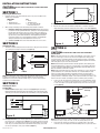
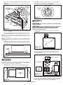
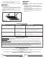
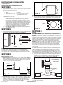
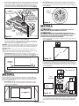
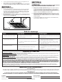
IMPORTANT INSTRUCTIONS OPERATING MANUAL
IL, ILK Series
In-Line Exhaust Fan
READ AND SAVE THESE INSTRUCTIONS
READ CAREFULLY BEFORE ATTEMPTING TO ASSEMBLE, INSTALL, OPERATE OR MAINTAIN THE PRODUCT DESCRIBED.
PROTECT YOURSELF AND OTHERS BY OBSERVING ALL SAFETY INFORMATION. FAILURE TO COMPLY WITH
INSTRUCTIONS COULD RESULT IN PERSONAL INJURY AND/OR PROPERTY DAMAGE!
RETAIN INSTRUCTIONS FOR FUTURE REFERENCE.
GENERAL SAFETY INFORMATION
When using electrical appliances, basic precautions
should always be followed to reduce the risk of fire,
electric shock and injury to person, including the following:
WARNING: TO REDUCE THE RISK OF FIRE, ELECTRIC SHOCK AND
INJURY TO PERSON, OBSERVE THE FOLLOWING:
a) Use this unit only in the manner intended by the manufacturer.If you
have questions, contact the manufacturer.
b) Before servicing or cleaning the unit, switch power off at service panel
and lock the service disconnecting means to prevent power from
being switched on accidentally. When the service disconnecting means
cannot be locked, securely fasten a prominent warning device, such as
a tag, to the service panel.
WARNING: TO REDUCE THE RISK OF FIRE, ELECTRIC SHOCK AND
INJURY TO PERSON, OBSERVE THE FOLLOWING:
a) Installation work and electrical wiring must be done by qualified
person(s) in accordance with all applicable codes and standards,
including fire-related construction.
b) Sufficient air is needed for proper combustion and exhausting
of gases through the flue (chimney) of fuel burning equipment
to prevent back drafting. Follow the heating equipment manufacturer’s
guideline and safety standards such as those published by the National
Fire Protection Association (NFPA) and the American Society for
Heating, Refrigeration, and Air Conditioning Engineers (ASHRAE), and
the local code authorities.
c) When cutting or drilling into wall or ceiling, do not damage electrical
wiring and other hidden utilities.
e) If this unit is to be installed over a tub or shower, it must be marked
as appropriate for the application and be connected to a GFCI (Ground
Fault Circuit Interrupter) - protected branch circuit.
f) This unit must be grounded.
g) To avoid motor bearing damage and noisy and/or unbalanced
impellers, keep drywall spray, construction dust, etc. off power unit.
h) Suitable for use with electronic speed control device.
i) Do not install into ceilings thermally insulated to a value greater than
R40.
CAUTION: FOR GENERAL VENTILATING USE ONLY. DO NOT USE
TO EXHAUST HAZARDOUS OR EXPLOSIVE MATERIALS AND VAPORS.
WARNING: DO NOT USE IN KITCHENS.
k) Read all instructions before installing or using exhaust fan.
WARNING: THE DUCTING FROM THIS FAN TO THE OUTSIDE OF
THE BUILDING HAS A STRONG EFFECT ON THE AIR FLOW, NOISE AND
ENERGY USE OF THE FAN. USE THE SHORTEST, STRAIGHTEST DUCT
ROUTING POSSIBLE FOR BEST PERFORMANCE, AND AVOID INSTALLING
THE FAN WITH SMALLER DUCTS THAN RECOMMENDED. INSULATION
AROUND THE DUCTS CAN REDUCE ENERGY LOSS AND INHIBIT MOLD
GROWTH. FANS INSTALLED WITH EXISTING DUCTS MAY NOT ACHIEVE
THEIR RATED AIRFLOW.
d) Ducted fans must always be vented to the outdoors.
SAVE THESE INSTRUCTIONS
A210952017 Rev. F 10-15
www.airkinglimited.com
1 of 8
INSTALLATION INSTRUCTIONS
CAUTION: MAKE SURE POWER IS SWITCHED OFF AT SERVICE PANEL BEFORE
STARTING INSTALLATION.
SECTION 1
Preparing the Exhaust Fan
1. Unpack fan from the carton and confirm that all pieces are present. In addition to the
exhaust fan you should have:
POWER UNITS
KITS
1 - Blower
1 - Blower
1 - Mounting Bracket
1 - Mounting Bracket
1 - Instruction/Safety Sheet 1 or 2 - Room Inlets with Grill
1 - Instruction/Safety Sheet
Figure 3
6" Inline Kits
2. Determine the location of the round intake assembly. Cut an 8" round hole through the
ceiling material being careful not to damage any electrical wires or other utilities (Figure 4).
2. When selecting fan mounting location, the following criteria should be considered:
a) Mounting to minimize noise generated by fan operation: Mounting the fan as far as
possible from the intake point will minimize fan operating noise from being transmitted
back through the duct work. If the fan is to be used as a booster for moving the air
between two rooms, a central point along the duct may be optimal. Insulated flexible
type duct work (recommended for all bathroom exhaust applications) will result in
much quieter operation. It is recommended that a minimum 8' of insulated flexible
ducting be used between any exhaust grill and fan for low noise level.
Joist
b) Service accessibility: Fan location should allow sufficient access for service.
SECTION 2
Installing the Fan
1. Attach the included mounting bracket to the wall stud or ceiling joist. Connect the fan to
the moutning bracket using the included screws (Figure 1).
Figure 4
SECTION 4
Ducting
CAUTION: ALL DUCTING MUST COMPLY WITH LOCAL AND NATIONAL
BUILDING CODES.
NOTE: The ducting from this fan to the outside of the building has a strong effect on the air
flow, noise and energy use of the fan. Use the shortest, straightest duct routing possible
for best performance, and avoid installing the fan with smaller ducts than recommended.
Insulation around the ducts can reduce energy loss and inhibit mold growth. Fans installed
with existing ducts may not achieve their rated air flow.
Joist/Stud
NOTE: Insulated ducting is required for bathroom exhaust applications, where ducting passes
through unconditioned space or where noise is a factor. Failure to use insulation could result in
excessive condensation buildup within the duct, and undesirable sound levels within the room.
Duct runs should have as few bends as possible.
Figure 1
Bracket
NOTE: Fan mounting can be at any point along the duct and in any angle, however, vertical
mounting is recommended to reduce condensation buildup in the fan. If a horizontal
installation is necessary and condensation buildup may pose a problem, wrap insulation
around the fan to minimize buildup.
NOTE: Flexible insulated ducting may be used where allowed by local code. For the quietest
possible installations, it is recommended a minimum of 8' of insulated flexduct be used
between any exhaust grill and fan. When using flexible type duct work, duct should be
stretched as tight and straight as possible. Failure to do so could result in dramatic loss of
system performance. Flexible duct should be connected to the fan with screw clamps or duct
tape. All connections should be as airtight as possible to maximize system performance.
1.
SECTION 3
Installing the Inlets
Connect one end of the ducting (not included) to the room level collar/damper and the
other end to the “Y” transition. Secure both ends in place using tape or a screw clamp
to create as air tight a seal as possible. Repeat this step for the other room level grill
housing (Figure 5).
4" Inline Kits
Exhaust to Wall/
Roof Cap
1a. New Constructions: Using the gauge on the fan’s housing (Figure 2), line up housing so
that it will be flush with the finished ceiling or wall. Position the fan so that the tabs rest flat
against the joist or stud and secure with four nails (not provided) to ensure proper installation.
Fan
“Y” Transition
Housing
Figure 5
Figure 2
1b. Existing Constructions: Position housing against the joist or stud and trace an outline of
the housing onto the ceiling/wall material (Figure 3). Set housing aside and cut opening,
being careful not to cut or damage any electrical or other hidden utilities. Place housing
next to the joist or stud and insure that it is flush with the finished ceiling. Secure with
four nails (not provided) to ensure proper installation (Figure 2).
A210952017 Rev. F 10-15
Housing
Ducting
NOTE: Units that include only one collar do not utilize the “Y” transition. Follow the same
instructions as in step 1, except connect the one end of the ducting directly to the fan.
2.
Ensure duct joints and exterior penetrations are sealed with caulk or other similar
material to create an air-tight path to minimize building heat loss or gain and to reduce
www.airkinglimited.com
2 of 8
the potential for condensation. Place/wrap insulation around duct and/or fan in order to
minimize possible condensation buildup within the duct, as well as building heat loss or
gain (Figure 6).
1b. 6" Inline Kits: Locate the damper adjustment knob in the center of the grill. While
pushing inward on the knob, twist the knob to adjust the damper to uncover as much of
the opening as is necessary to balance the system (Figure 9).
Roof Cap*
(with built-in
damper)
Insulation*
(place around and
over inlet
Adjustment
Knob
Keep duct
runs short
Inlet
Figure 9
SECTION 6
Seal gaps
around Inlet
Wiring the Fan
Round
Duct*
CAUTION: MAKE SURE POWER IS SWITCHED OFF AT SERVICE PANEL BEFORE
STARTING INSTALLATION.
Seal duct joints
with tape
CAUTION: ALL ELECTRICAL CONNECTIONS MUST BE MADE IN ACCORDANCE
Figure 6
*Purchase separately
3.
Connect one end of the ducting to the top of the “Y” transition and the other end to the
intake of the fan (Figure 5).
4.
Connect one end of the ducting to the exhaust of the fan and the other end to a wall or
ceiling cap (Figure 5). Always duct the fan to the outside through a wall or roof cap.
WITH LOCAL CODES, ORDINANCES, OR NATIONAL ELECTRICAL CODE. IF YOU ARE
UNFAMILIAR WITH METHODS OF INSTALLING ELECTRICAL WIRING, SECURE THE
SERVICES OF A QUALIFIED ELECTRICIAN.
1.
Remove the screws securing the terminal box cover plate located on the side of the
motor (Figure 10).
NOTE: When using insulated flex duct, it is recommended that the inner vinyl core be screw
clamped or taped to the inlet and outlet and that the vapor barrier surrounding the insulation
be taped to the fan housing.
NOTE: When attaching flex duct to the collar/damper combination and an immediate elbow is
necessary, be certain that the elbow is installed with a “soft” bend to allow damper blades to
operate properly.
5.
6" Inline Kits: Once the ducting has been connected to the room intake assembly,
press the grill up into the previously cut hole until the spring loaded ceiling holders snap
in place (Figure 7).
Screws
Figure 10
Ceiling
Holders
2.
Run wiring from an approved wall switch carrying the appropriate rating. One neutral
(white) one hot (black lead connected to the switch) and one ground (green or bare
wire). Loosen the wire strain relief bar and run the wires through the wire access
nut and the strain relief, making sure to leave enough wire to make all electrical
connections (Figure 11).
Figure 7
Wire Access Nut
SECTION 5
Balancing the System
For systems with more than one inlet, it may be nesseccary to balance the air flow depending
on the location of the inlets. The system can be balance at room level using the adjustable
dampers located inside the inlet housing. To adjust the damper:
Strain Relief Bar
1a. 4" Inline Kits: Locate the damper inside of the inlet housing and slide it to cover or
uncover as much of the opening as is necessary to balance the system (Figure 8).
G - Ground
B - Black
W - White
Damper
G
B
W
Figure 11
3.
Figure 8
A210952017 Rev. F 10-15
Insert the white wire from the house into the terminal strip with the white wire and
tighten using a small regular screwdriver. Insert the black wire from the wall switch
into the terminal strip with the black wire and tighten using a small regular screwdriver.
Insert the green (or bare) ground wire from the house into the terminal strip with the
green wire and tighten using a small regular screwdriver (Figure 11).
www.airkinglimited.com
3 of 8
4.
Tighten the screws holding the strain relief bar in place. Also tighten the wire access
nut. This will create a water-resistant seal (Figure 11).
SECTION 8
5.
Check to make sure all wire connections are securely fastened to the terminal strip.
Replace the wire compartment cover and re-install the two screws removed in Step 1.
CAUTION: MAKE SURE POWER IS SWITCHED OFF AT SERVICE PANEL BEFORE
SERVICING THE UNIT.
SECTION 7
Completing the Installation
1.
Use and Care
Use a sealant appropriate for contact with the building materials present and for the
temperature requirements of the installation to prevent air leakage from unconditioned
spaces is recommended. If gaps between unit housing and ceiling are great, additional
material (backing rod, ceiling material) may be required.
2. 4" Inline Kits: Install the grill into the inlets by squeezing the two ends of the springs
together and installing them up into the slots of the fan. Push the grill up into position
(Figure 12).
1a. Cleaning the Grill (4" Inine Kits): Remove grill and use a mild detergent, such as
dishwashing liquid, and dry with a soft cloth. NEVER USE ANY ABRASIVE PADS OR
SCOURING POWDERS. Completely dry grill before reinstalling. Refer to instructions in
Step 2 of Section 7, to reinstall grill.
1b. Cleaning the Grill (6" Inine Kits): With the grill in place, wipe with a damp cloth or
gently vacuum. NEVER USE ANY ABRASIVE PADS OR SCOURING POWDERS. Completely
dry grill before turing the power back on.
2.
The fan’s bearings are sealed and provided with an internal lubricating material, no
additional lubrication is necessary.
Figure 12
3.
Restore power and test your installation.
Troubleshooting Guide
Trouble
Probable Cause
1. Fan does not operate when the switch is on.
A fuse may be blown or a circuit tripped.
1a. Replace fuse or reset circuit breaker.
1a.
Suggested Remedy
1b.
Wiring is not connected properly.
1b. Turn off power to unit. Check that all wires are connected.
1c.
Motor has stopped operating.
1c. Replace motor.
2. Fan is operating, but air moves slower than normal.
2a.
Obstruction in the exhaust ducting.
2a. Check for any obstructions in the ducting. The most common are bird nests
in the roof cap or wall cap where the fan exhausts to the outside.
2b.
Speed control not set high enough.
2b. If a speed control is being used, confirm the setting.
2c.
Incorrect wiring.
2c. Turn off power to unit. Check that all wires are connected correctly.
3. Fan is operating louder than normal.
3a.
Motor is loose.
3a. Turn off power to unit. Confirm unit is mounted securely to bracket.
Restore power to unit.
3b.
Fan mounting screws too tight.
3b. Turn off power to the unit. Loosen screws going through rubber grommets
3c.
Fan damaged in shipping.
3c. Contact seller for replacement.
LIMITED WARRANTY
WHAT THIS WARRANTY COVERS: This product is warranted against defects in workmanship and/or materials.
HOW LONG THIS WARRANTY LASTS: This warranty extends only to the original purchaser of the product and lasts for five (5) years from the date of original purchase or until the original purchaser of
the product sells or transfers the product, whichever first occurs.
WHAT AIR KING WILL DO: During the warranty period, Air King will, at its sole option, repair or replace any part or parts that prove to be defective or replace the whole product with the same or
comparable model.
WHAT THIS WARRANTY DOES NOT COVER: This warranty does not apply if the product was damaged or failed because of accident, improper handling or operation, shipping damage, abuse, misuse,
unauthorized repairs made or attempted. This warranty does not cover shipping costs for the return of products to Air King for repair or replacement. Air King will pay return shipping charges from Air
King following warranty repairs or replacement
ANY AND ALL WARRANTIES, EXPRESSED OR IMPLIED (INCLUDING, WITHOUT LIMITATION, ANY IMPLIED WARRANTY OF MERCHANTABILITY), LAST ONE YEAR FROM THE DATE OF ORIGINAL
PURCHASE OR UNTIL THE ORIGINAL PURCHASER OF THE PRODUCT SELLS OR TRANSFERS THE PRODUCT, WHICHEVER FIRST OCCURS AND IN NO EVENT SHALL AIR KING’S LIABILITY UNDER
ANY EXPRESS OR IMPLIED WARRANTY INCLUDE (I) INCIDENTAL OR CONSEQUENTIAL DAMAGES FROM ANY CAUSE WHATSOEVER, OR (II) REPLACMENT OR REPAIR OF ANY HOUSE FUSES,
CIRCUIT BREAKERS OR RECEPTACLES. NOTWITHSTANDING ANYTHING TO THE CONTRARY, IN NO EVENT SHALL AIR KING’S LIABILITY UNDER ANY EXPRESS OR IMPLIED WARRANTY EXCEED
THE PURCHASE PRICE OF THE PRODUCT AND ANY SUCH LIABILITY SHALL TERMINATE UPON THE EXPIRATION OF THE WARRANTY PERIOD.
Some states and provinces do not allow limitations on how long an implied warranty lasts, or the exclusion or limitation of incidental or consequential damages, so these exclusions or limitations may not apply to
you. This warranty gives you specific legal rights. You may also have other rights which vary from state to state and province to province. Proof of purchase is required before a warranty claim will be accepted.
CUSTOMER SERVICE:
Toll-Free (800) 465-7300
Our Customer Service team is available to assist you with product questions, service center locations, and replacement parts. They can be reached Monday through Friday, 8am-4pm Eastern. Please have
your model number available, as well as the type and style (located on the label inside of your product).
Please do not return product to place of purchase.
www.airkinglimited.com
PARTS FOR DISCONTINUED, OBSOLETE AND CERTAIN OTHER PRODUCTS MAY NOT BE AVAILABLE. DUE TO SAFETY REASONS, MANY ELECTRONIC COMPONENTS AND MOST HEATER
COMPONENTS ARE NOT AVAILABLE TO CONSUMERS FOR INSTALLATION OR REPLACEMENT.
Installer:
Installation Date:
Place of Purchase:
Model Number:
A210952017 Rev. F 10-15
www.airkinglimited.com
4 of 8
INSTRUCTIONS IMPORTANTES –
MODE D’EMPLOI
Ventilateur d’évacuation
en série
Séries IL, ILK
LIRE ET CONSERVER CES INSTRUCTIONS
LIRE SOIGNEUSEMENT AVANT DE TENTER D’ASSEMBLER, INSTALLER, OPÉRER OU DE RÉPARER LE PRODUIT DÉCRIT. PROTÉGEZ
VOUS-MÊME ET LES AUTRES EN OBSERVANT TOUTE L’INFORMATION DE SÉCURITÉ. FAILLIR À SE CONFORMER AUX
INSTRUCTIONS PEUT RÉSULTER EN BLESSURE PERSONNELLE GRAVE ET/OU EN DOMMAGE À LA PROPRIÉTÉ.
CONSERVER CES INSTRUCTIONS POUR RÉFÉRENCES FUTURES.
INSTRUCTIONS GÉNÉRALES DE SÉCURITÉ
Lors de l’utilisation d’appareils électriques, des précautions de base doivent
toujours être suivies pour réduire les risques d’incendie, de choc électrique et de
blessures corporelles, incluant ce qui suit:
AVERTISSEMENT : POUR RÉDUIRE LES RISQUES
e) Si cette unité doit être installée au-dessus d’une baignoire ou d’une
douche, elle doit être marquée comme approprié pour l’application et être
reliée à un GFCI (disjoncteur de fuite à la terre) - circuit électrique protégé.
a) Utiliser cette unité seulement de la manière pour laquelle le fabricant
l’a conçu. Si vous aviez des questions, veuillez contacter le fabricant.
f) Cette unité doit être mise à la terre.
D’INCENDIE, DE CHOC ÉLECTRIQUE OU DE BLESSURES PERSONNELLES
OBSERVER CE QUI SUIT :
b) Avant d’effectuer un service ou de nettoyer l’unité, couper l’alimentation
électrique dans le panneau de distribution et verrouiller le dispositif de
déconnexion afin d’éviter que l’alimentation ne revienne accidentellement.
Lorsque le dispositif ne peut être verrouillé, fixer solidement un avis
d’avertissement, tel qu’une étiquette, au panneau de distribution.
AVERTISSEMENT : POUR RÉDUIRE LES RISQUES
D’INCENDIE, DE CHOC ÉLECTRIQUE OU DE BLESSURES PERSONNELLES
OBSERVER CE QUI SUIT :
a) Le travail d’installation et le câblage électrique doivent être effectués
par une(des) personne(s) qualifiée(s) en conformité avec tous les codes
et normes applicables, incluant la construction relative aux incendies.
b) De l’air en quantité suffisante est requis pour la bonne combustion et
l’évacuation de gaz par le conduit (cheminée) provenant d’équipement
de brûlage au combustible pour prévenir un refoulement. Suivre les
directives du fabricant de l’équipement de chauffage et les normes
de sécurité telles que celles publiées par la National Fire Protection
Association (NFPA) et de la American Society for Heating, Refrigeration,
and Air Conditioning Engineers (ASHRAE), et de celles des autorités
locales du code.
c) Lors de coupe ou de perçage des murs et plafonds, ne pas
endommager le filage électrique et autres utilités cachées.
d) Les ventilateurs avec conduits doivent toujours être évacués vers
l’extérieur.
g) Pour éviter des dommages aux roulements des moteurs et/ou des
hélices bruyantes ou déséquilibrées, empêcher la poussière de cloison
sèche, poussière de construction, etc., d’atteindre l’unité de puissance.
h) Approprié pour l’usage avec le dispositif de commande électronique de
vitesse.
i) N’installez pas sur des plafonds thermiquement isolés à une valeur
plus grande que R40.
ATTENTION : POUR USAGE DE VENTILATION GÉNÉRALE
EXCLUSIVEMENT. NE PAS UTILISER POUR ÉVACUER DU MATÉRIEL ET
DES VAPEURS DANGEREUSES OU EXPLOSIVES.
AVERTISSEMENT : NE PAS UTILISER DANS LES CUISINES
k) Bien lire toutes les instructions avant d’installer ou d’utiliser le
ventilateur d’évacuation.
AVERTISSEMENT :
LA CANALISATION DE CE VENTILATEUR
À L’EXTÉRIEUR DU BÂTIMENT A UN EFFET IMPORTANT SUR LE FLUX
D’AIR, LE BRUIT ET LA CONSOMMATION D’ÉNERGIE DU VENTILATEUR.
UTILISEZ LA ROUTE DE CANALISATION LA PLUS COURTE ET LA PLUS
DROITE POSSIBLE POUR UNE MEILLEURE PERFORMANCE, ET ÉVITEZ
D’INSTALLER LE VENTILATEUR AVEC DES CONDUITS PLUS PETITS QUE
RECOMMANDÉ. L’ISOLATION AUTOUR DES CONDUITS PEUT RÉDUIRE LA
PERTE D’ÉNERGIE ET EMPÊCHER LE DÉVELOPPEMENT DE MOISISSURES.
IL SE PEUT QUE LES VENTILATEURS INSTALLÉS AVEC DES CONDUITS
EXISTANTS N’ATTEIGNENT PAS LEUR DÉBIT D’AIR NOMINAL.
CONSERVER CES INSTRUCTIONS
A210952017 Rev. F 10-15
www.airkinglimited.com
5 of 8
INSTRUCTIONS D’INSTALLATION
ATTENTION : VOUS ASSURER QUE L’ALIMENTATION EST COUPÉE AU
PANNEAU DE SERVICE AVANT DE COMMENCER L’INSTALLATION.
SECTION 1
Préparation en prévision de l’installation du ventilateur
1. Sortir le ventilateur de sa boite et confirmer que toutes les pièces sont présentes. En plus
du ventilateur d’évacuation vous devriez avoir:
UNITÉS D’ALIMENTATION
KITS
1 - Soufflante
1 - Soufflante
1 - Traverses de Montage
1 - Traverses de Montage
1 - Feuillet d’instructions / sécurité 1 ou 2 - entrées de chambre avec grill
1 - Feuillet d’instructions / sécurité
2. Lorsque vous choisissez l’emplacement pour l’installation du ventilateur, les critères
suivants doivent être pris en compte :
a) Installation visant à réduire le bruit généré par le fonctionnement du ventilateur :
L’installation du ventilateur aussi loin que possible du point d’entrée empêchera, en
partie, le bruit de son fonctionnement d’être retransmis par le truchement du système
de conduits. S’il est utilisé comme ventilateur de renfort pour assurer la distribution
d’air entre deux pièces, un point central au long du système de conduit pourrait s’avérer
optimal. Un système de conduit flexible isolé (recommandé pour toutes les installations
de ventilateurs dans les salles de bain) procurera un fonctionnement beaucoup plus
silencieux. Il est recommandé d’utiliser au moins 2,44 m de gaine flexible entre toute
grille d’échappement et le ventilateur pour minimiser le niveau de bruit.
b) Accessibilité pour l’entretien : L’emplacement du ventilateur devrait prévoir un
accès suffisant pour l’entretien.
SECTION 2
Installation du ventilateur
1. Fixez le support de montage inclus au poteau mural ou à la solive de plafond. Connectez
le ventilateur au support de montage à l’aide des vis fournies (Figure 1).
Figure 3
Kits d’alignement de 6 po
2. Déterminez l’emplacement de l’ensemble d’aspiration circulaire. Découpez un trou circulaire
de 8 po à travers le matériau de plafond en faisant attention de ne pas endommager les fils
électriques ou d’autres utilités (Figure 4).
Montant
Figure 4
SECTION 4
Conduit
ATTENTION : TOUS LES CONDUITS DOIVENT ÊTRE CONFORMES AVEC LES
Montant /
Solive
Figure 1
Support
REMARQUE : Le ventilateur peut être installé à l’emplacement de votre choix le long
du conduit, cependant, une installation verticale est recommandée afin de minimiser
l’accumulation de condensation dans l’unité. Dans le cas où une installation horizontale
s’avère nécessaire et que l’accumulation de condensation pourrait occasionner un problème,
enveloppez le ventilateur d’isolant afin d’en minimiser l’accumulation.
SECTION 3
Installation des entrées
Kits d’alignement de 4 po
1a. Nouvelle construction : En utilisant les marques sur le cabinet du ventilateur (Figure 2),
aligner le cabinet pour qu’il affleure le plafond fini ou le mur. Positionner le ventilateur de
sorte que les onglets reposent contre la solive ou le montant et le fixer à l’aide de quatre
clous (non-fournis) pour assurer une installation adéquate.
CODES DU BATIMENT LOCAUX ET NATIONAUX.
REMARQUE : La canalisation de ce ventilateur à l’extérieur du bâtiment a un effet important sur
le flux d’air, le bruit et la consommation d’énergie du ventilateur. Utilisez la route de canalisation
la plus courte et la plus droite possible pour une meilleure performance, et évitez d’installer le
ventilateur avec des conduits plus petits que recommandé. L’isolation autour des conduits peut
réduire la perte d’énergie et empêcher le développement de moisissures. Il se peut que les
ventilateurs installés avec des conduits existants n’atteignent pas leur débit d’air nominal.
REMARQUE :Un conduit isolé est requis pour les installations d’évacuations de salles de bain,
lorsque le conduit passe par un emplacement non climatisé ou dans un emplacement où le
bruit représente un facteur important. Le fait de ne pas utiliser d’isolant pourrait entraîner
une accumulation excessive de condensation au sein du conduit de même qu’un niveau de
sonorité indésirable dans la pièce. Les courses de conduits devraient présenter aussi peu de
coudes que possible.
REMARQUE : Des conduits isolés flexibles peuvent être utilisés là où le code local le permet. Pour
des installations au niveau de sonorité le plus bas possible, il est recommandé d’utiliser au moins
2,44 m de conduit flexible entre toute grille d’échappement et ventilateur. Lors de l’utilisation de
systèmes de conduit de type flexible, le conduit devrait être étiré aussi serré et droit que possible.
Le cas contraire pourrait entraîner une baisse dramatique de rendement du système. Le conduit
flexible devrait être rattaché au ventilateur à l’aide de serre-joints ou de ruban à conduits. Toutes les
connexions devraient être aussi étanches que possible afin de maximiser le rendement du système.
1. Raccordez une extrémité du conduit (non inclus) au collet / clapet au niveau de la pièce
et l’autre extrémité à l’embranchement en “Y ”. Fixez les deux extrémités en place en
utilisant du ruban ou un serre-joint afin de créer un joint aussi étanche que possible.
Répétez cette étape pour le châssis de la grille de l’autre pièce (Figure 5).
Evacuation vers
le capuchon du
mur / plafond
Ventilateur
Embranchement
en “ Y ”
Cabinet
Figure 2
1b. Construction existante : Positionner le cabinet contre la solive ou le montant et tracer le
contour du cabinet sur le matériau du mur / plafond (Figure 3). Mettre le cabinet de côté
et découper l’ouverture, en prenant bien soin de ne pas couper ou endommager d’utilité
électrique ou dissimulée. Placer le cabinet près de la solive ou du montant et vous
assurer qu’il soit à effleurement avec le plafond fini ou avec le mur. Fixer avec quatre
clous (non-fournis) pour assurer une installation adéquate (Figure 2).
A210952017 Rev. F 10-15
Figure 5
Cabinet
Conduit
REMARQUE : Les unités qui incluent un seul collet n’ont pas besoin d’embranchement en
“ Y ”. Suivez les mêmes directives qu’à l’étape 1, sauf que vous raccordez l’extrémité du
conduit directement au ventilateur.
www.airkinglimited.com
6 of 8
2.
Assurez-vous que les joints des conduits et les pénétrations extérieures sont scellés avec du
mastic ou tout autre matériau similaire pour créer un passage d’air étanche afin de minimiser
la perte ou le gain de chaleur et réduire le risque de condensation. Placez / enveloppez
l’isolant autour du conduit et / ou ventilateur afin de minimiser la possibilité d’accumulation
de condensation à l’intérieur du conduit, ainsi que la perte ou le gain de chaleur (Figure 6).
Capuchon de toit*
(avec amortisseur
intégré)
Isolant*
(placer autour et audessus du entrée)
Bouton de
réglage
Garder les
canalisations courtes
Entrée
Figure 9
SECTION 6
Câblage du ventilateur
Sceller les
espaces autour
du entrée Conduit
rond*
Figure 6
1b. Kits d’alignement de 6 po : Localisez le bouton de réglage de l’amortisseur dans le
centre du gril. Tout en poussant vers l’intérieur sur le bouton, tournez le bouton pour
ajuster l’amortisseur et découvrir autant de l’ouverture que nécessaire pour équilibrer le
système (Figure 9).
ATTENTION : VOUS ASSURER QUE L’ALIMENTATION EST COUPÉE AU
PANNEAU DE SERVICE AVANT DE COMMENCER L’INSTALLATION.
ATTENTION : TOUTES LES CONNEXIONS DOIVENT ÊTRE FAITES EN
Sceller les joints
avec du ruban
*Acheter séparément
2.
Raccordez une extrémité du conduit à la partie supérieure de l’embranchement en “ Y ”
et l’autre extrémité à la prise d’entrée du ventilateur (Figure 5).
3. Raccordez une extrémité du conduit à l’évacuation du ventilateur et l’autre extrémité
à un capuchon de mur ou de plafond (Figure 5). Toujours canaliser le ventilateur vers
l’extérieur par le biais d’un capuchon de mur ou de plafond.
REMARQUE : Lorsqu’un conduit isolé flexible est utilisé, il est recommandé de fixer l’âme de
vinyle interne du trou d’entrée et de sortie à l’aide d’une vis de serrage ou de ruban adhésif
et que le pare-vapeur entourant le revêtement isolant soit fixé à l’aide de ruban adhésif au
châssis du ventilateur.
REMARQUE : Lorsqu’il est nécessaire de joindre un conduit flexible à l’ensemble collet /
clapet et qu’un coude immédiat s’avère nécessaire, assurez-vous qu’il s’agisse d’un coude
“ flexible ” de sorte à assurer le bon fonctionnement des lames du clapet.
4. Kits d’alignement de 6 po : Une fois que la canalisation a été reliée à l’ensemble
d’aspiration de la pièce, appuyez sur le gril vers le haut dans le trou préalablement coupé
jusqu’à ce que les détenteurs de plafond à ressort enclenchent en place (Figure 7).
CONFORMITÉ AVEC LES CODES ÉLECTRIQUES LOCAUX OU NATIONAUX. SI VOUS N’ÊTES
PAS FAMILIER AVEC LES MÉTHODES D’INSTALLATION DE CÂBLAGE ÉLECTRIQUE,
RECOURREZ AUX SERVICES D’UN ÉLECTRICIEN QUALIFIÉ.
1.
Retirez les vis de la plaque du couvercle de la boîte de raccordement située sur le côté
du moteur (Figure 10).
Vis
Figure 10
Détenteurs
de plafond
2.
Passez les câbles partir d’un interrupteur mural approuvé et de capacité appropriée.
Un neutre (blanc) un chaud (fil noir connecté au commutateur) et un de terre (fil vert ou
nu). Desserrez la barre anti-traction et passez les fils à travers l’écrou d’accès de fil et
l’anti-traction, en veillant à laisser suffisamment de fil pour faire tous les raccordements
électriques (Figure 11).
Figure 7
Écrou d’accès de fil
SECTION 5
Équilibrage du système
Pour des systèmes avec plus d’un orifice d’entrée, il peut être nécessaire d’équilibrer le
flux d’air en fonction de l’emplacement des orifices d’entrée. Le système peut être équilibré
au niveau de la chambre à l’aide des amortisseurs réglables situés à l’intérieur du boîtier
d’entrée. Pour régler l’amortisseur :
1a. Kits d’alignement de 4 po : Localisez l’amortisseur à l’intérieur du boîtier d’entrée
et faites-le glisser pour couvrir ou découvrir autant de l’ouverture que nécessaire à
l’équilibre du système (Figure 8).
Barre
anti-traction
G - Fil de Masse
B - Noir
W - Blanc
G
B
W
Clapet
Figure 11
3.
Figure 8
A210952017 Rev. F 10-15
Insérez le fil blanc de la maison dans le bornier avec le fil blanc et serrez à l’aide d’un petit
tournevis régulier. Insérez le fil noir de l’interrupteur mural dans le bornier avec le fil noir et
serrez à l’aide d’un petit tournevis régulier. Insérez le fil vert (ou nu) de terre de la maison
dans le bornier avec le fil vert et serrez à l’aide d’un petit tournevis régulier (Figure 11).
www.airkinglimited.com
7 of 8
4.
5.
Serrez les vis qui retiennent la barre anti-traction en place. Serrez également l’écrou
d’accès de fil. Ceci créera un joint d’étanchéité (Figure 11).
Assurez-vous que toutes les connexions sont solidement attachées au bornier. Replacez
le couvercle du compartiment de câblage et réinstallez les deux vis retirées à l’étape 1.
SECTION 8
Utilisation et entretien
ATTENTION : ASSUREZ-VOUS QUE LE COURANT EST COUPE A PARTIR DU
PANNEAU ELECTRIQUE AVANT DE PROCEDER A L’ENTRETIEN DE L’UNITE.
SECTION 7
Complétion de l’installation
1. Il est recommandé d’utiliser un scellant approprié pour le contact avec les matériaux
de construction actuels et pour les besoins de la température de l’installation, afin
d’empêcher les fuites d’air à partir des espaces non conditionnés. S’il y a des grands
écarts entre le boîtier de l’appareil et le plafond, du matériel supplémentaire (tige de
support, matériel de plafond) peut être nécessaire.
2. Kits d’alignement de 4 po : Installez le gril dans les entrées en appuyant ensemble sur
les deux extrémités des ressorts et les installant dans les fentes du ventilateur. Poussez
le gril vers le haut en position (Figure 12).
1a. Nettoyage de la grille (Kits d’alignement de 4 po) : Retirez la grille et nettoyez-là
à l’aide d’un détergent doux, comme du savon à vaisselle, et séchez-là ensuite avec
un chiffon doux. NE JAMAIS UTILISER DE TAMPONS ABRASIFS OU DE POUDRES A
RECURER. Asséchez la grille complètement avant de la réinstaller. Reportez-vous aux
instructions à l’étape 2 de la Section 7 pour réinstaller la grille.
1b. Nettoyage de la grille (Kits d’alignement de 6 po): Avec la grille en place, essuyez
avec un chiffon humide ou nettoyez légèrement sous vide. NE JAMAIS UTILISER DE
TAMPONS ABRASIFS OU DE POUDRES A RECURER. Séchez complètement le gril avant
de rallumer l’appareil.
2.
Les roulements du ventilateur sont scellés et munis d’un matériel lubrifiant interne,
aucune lubrification additionnelle n’est requise.
Figure 12
3.
Rétablissez le courant et testez votre installation.
Guide de dépannage
Trouble
Cause Possible
Solution Suggérée
1. Le ventilateur ne fonctionne pas lorsque
1a. Un fusible peut être grillé ou un disjoncteur peut être décle.nché.
1a. Remplacer le fusible ou réinitialiser le disjoncteur.
l’interrupteur est à la position en marche.
1b. Le câblage n’est pas raccordé correctement.
1b. Couper l’alimentation de l’unité. Vérifier que tous les fils sont raccordés.
1c. La moteur est terminee
1c. Remplacez la moteur
2. Le ventilateur fonctionne, mais l’air
2a. Obstruction dans les conduits d’évacuation.
2a. Vérifier pour toute obstruction dans les conduits. Les plus courantes
circule plus lentement que la normale. sont des nids d’oiseau dans le chapeau de toit ou mural là où le
ventilateur s’évacue s’évacue vers l’extérieur.
2b. Le réglage de la commande de vitesse n’est pas assez élevé. 2b. Si une commande de vitesse est utilisée, confirmez le réglage.
2c. Câblage incorrect.
2c. Coupez l’alimentation de l’unité. Assurez-vous que tous les fils
sont branchés correctement.
3. Le ventilateur fonctionne de manière
3a. Le moteur est lâche.
3a. Couper l’alimentation à l’unité. Retirer la grille et vérifier que toutes les
plus bruyante que la normale. vis sont complètement serrées. Remettre l’alimentation sur l’unité.
3b. Les vis pour l’installation du ventilateur sont trop serrées.
3b. Coupez l’alimentation de l’unité. Desserrez les vis des passe-câbles
en caoutchouc.
3c. Ventilateur endommagé au cours de l’expédition.
3c. Communiquez avec le vendeur pour un remplacement.
GARANTIE LIMITÉE
QUE COUVRE CETTE GARANTIE : Ce produit est garanti contre tout vice de fabrication ou de matière.
COMBIEN DE TEMPS CETTE GARANTIE DURE : Cette garantie se rapporte seulement à l’acheteur original du produit et dure pendant cinq (5) années de la date de l’achat original ou jusqu’à ce que
l’acheteur original du produit vend ou transfère le produit, celui qui se produit en premier.
QUE FERA AIR KING : Au cours de la période de garantie, Air King, à son choix, réparera ou remplacera n’importe quelle partie ou pièces qui s’avèrent défectueuses ou remplacera le produit entier par
le même modèle ou un modèle comparable.
CE QUE CETTE GARANTIE NE COUVRE PAS : Cette garantie ne s’applique pas si le produit était endommagé ou arrête de fonctionner en raison d’un accident, d’une mauvaise manipulation ou
opération, de dommages d’expédition, d’abus, de mauvaise utilisation, de réparation faite ou tentées non autorisées. Cette garantie ne couvre pas les coûts d’expédition pour le retour des produits à
Air King pour la réparation ou le remplacement. Air King payera les frais d’expédition de retour de Air King après les réparations ou le remplacement de garantie.
TOUTES LES GARANTIES, EXPRESSES OU TACITES (COMPRENANT, SANS LIMITATION, TOUTE GARANTIE TACITE DE VALEUR MARCHANDE), DURENT UN AN DE LA DATE DE L’ACHAT ORIGINAL OU
JUSQU’À CE QUE L’ACHETEUR ORIGINAL DU PRODUIT VEND OU TRANSFÈRE LE PRODUIT, CELUI QUI SE PRODUIT EN PREMIER ET DANS AUCUN CAS AIR KING N’ASSUME AUCUNE RESPONSABILITÉ
EXPRESSE OU TACITE POUR (I) DES DOMMAGES ACCIDENTELS OU INDIRECTS DE N’IMPORTE QUELLE CAUSE, OU (II) LE REPLACEMENT OU LA RÉPARATION DE TOUS FUSIBLES, DISJONCTEURS OU
RÉCEPTACLES DE MAISON. MALGRÉ N’IMPORTE QUOI À L’EFFET CONTRAIRE, DANS AUCUN CAS LA RESPONSABILITÉ D’AIR KING, SOUS UNE GARANTIE EXPRESSE OU TACITE, NE DÉPASSERA LE
PRIX D’ACHAT DU PRODUIT ET UNE TELLE RESPONSABILITÉ SE TERMINERA AVEC L’EXPIRATION DE LA PÉRIODE DE GARANTIE.
Certains états et provinces ne permettent pas les limitations de la période de garantie, ou l’exclusion ou la restriction des dommages accidentels ou indirects, et, par conséquent, les présentes
restrictions ne peuvent pas s’appliquer. La présente garantie vous donne des droits légaux spécifiques et peut-être certains autres droits qui peuvent varier selon la province. La preuve d’achat est
exigée avant qu’une réclamation de garantie ne soit acceptée.
SERVICE À LA CLIENTÈLE :
Sans frais (800) 465-7300
Notre équipe de service à la clientèle est disponible pour vous aider avec des questions sur le produit, les adresses des centres de service, et les pièces de rechange. Vous pouvez la rejoindre, du lundi
au vendredi, de 8h:00 à 16h:00 HNE. Veuillez avoir le numéro du modèle disponible, ainsi que le genre et le style (qui se trouvent sur l’étiquette à l’intérieur de votre produit). Veuillez ne pas renvoyer le
produit à l’endroit de l’achat.
www.airkinglimited.com
IL SE PEUT QUE LES PIÈCES POUR LES PRODUITS DISCONTINUÉS, OBSOLÈTES ET AUTRES PRODUITS NE SOIENT PAS DISPONIBLES. POUR DES RAISONS DE SÛRETÉ, BEAUCOUP DE
COMPOSANTS ÉLECTRONIQUES ET LA PLUPART DES COMPOSANTS DES CHAUFFAGES NE SONT PAS À LA DISPOSITION DES CONSOMMATEURS POUR L’INSTALLATION OU LE REMPLACEMENT.
Installateur :
Date d’installation :
Endroit de l’achat :
Numéro de modèle :
A210952017 Rev. F 10-15
www.airkinglimited.com
8 of 8