1
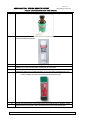
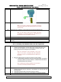
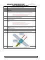
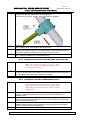
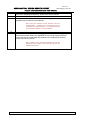
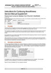
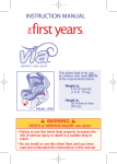
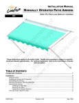
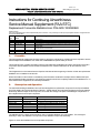
AERONAUTICAL DESIGN SERVICE REPORT REPORT NO ADS 100517-1-15-FAA PROJECT: COMANCHE STABILATOR HORN APPROVAL Instructions for Continuing Airworthiness Service Manual Supplement (FAA STC) Replacement Comanche Stabilator Horn P/No ADS 1002080828 Revisions Notes This report at its latest revision status superseded all previous revisions. Only a total reprint of the report promulgates revisions. All pages bear the same revisions/date status Rev No. Revision Date 0 1 2 3 3 Nov 2010 18 Nov 2010 24 Mar 2011 4 11 Apr 2011 5 6 5 July 2011 11 July 2013 1. Signature Details of Change Original Issue Editorial Minor Corrections in terminology added. Bolt Orientations corrected in Drawings. Reference made to apply and Check “Torque Seal” Removed PA40, updated references, updated temperature references, updated service manual section. Updated service manual section. Updated in Response to FAA email Dated 10 July 2013. Preamble This Service Manual Supplement has been raised to specify the maintenance activities which are required to ensure that the Replacement Stabilator Horn P/No ADS 1008020828 will operate safely in service. This supplement only contains information which is associated with the Replacement Horn and needs to be read in conjunction with the PIPER Comanche Service Manual which contains instructions for all other features of the aircraft. This Supplement is to be inserted into the Piper Service Manual at the beginning of Section 5 when the replacement Stabilator horn is installed on the aircraft. Where information in this manual is contradictory with information contained in the Piper Service Manual the Piper Service Manual will take precedence over all things except those which are explicitly stated for the stabilator horn. In those instances this supplement, should take precedence. 2. Description and Operation The Aeronautical Designs Stabilator Horn has been designed as a replacement component for the Piper Stabilator horn P/No 20397-00 in the aircraft listed in Table #1. Added strength and manufacturing features have generated a distinctively different shape for this component. Even with this change in shape the AeroDesigns Component is a direct replacement for the Piper Component. Models Affected PA-24 PA 24-250 PA 24-260 PA24-400 PA 30 PA 39 Type Comanche Comanche Comanche Comanche Twin Comanche Twin Comanche Serial Numbers Affected 24-1 through 24-3687 24-1, 24-103 through 24-3687 24-3642 and 24-4000 through 24-5034 26-2 through 26-148 30-1 through 30-2000 39-1 through 39-162 The stabilator horn is a fixed component which has no operating features once it is installed. The next higher assembly in which the stabilator is a component is the Stabilator Torque tube assembly. Figure #1 shows the Stabilator Horn as a separate component. PAGE 1 OF 16 AERONAUTICAL DESIGN SERVICE REPORT REPORT NO ADS 100517-1-15-FAA PROJECT: COMANCHE STABILATOR HORN APPROVAL Figure 1 Figure #2 shows the Stabilator torque tube assembly and includes the Parts List. . Figure 2 PAGE 2 OF 16 AERONAUTICAL DESIGN SERVICE REPORT REPORT NO ADS 100517-1-15-FAA PROJECT: COMANCHE STABILATOR HORN APPROVAL 3. Airworthiness Limitations No additional airworthiness limitations are required for this modification. This Airworthiness Limitations Section is FAA Approved and Specifies Maintenance required under Secs.. 43.16, and 91.403 of the Federal Aviation Regulations unless an alternative program has been FAA approved. PAGE 3 OF 16 AERONAUTICAL DESIGN SERVICE REPORT REPORT NO ADS 100517-1-15-FAA PROJECT: COMANCHE STABILATOR HORN APPROVAL 5. Servicing Servicing procedures specified in the Piper Comanche Service Manual continue to apply when this Aeronautical Designs Stabilator horn is fitted however additional inspections are required to check features which are unique to this component. The additional instructions specified in Figure #3 are to be completed at each 100 hourly inspection of the aircraft. This servicing is done with the stabilator installed on the aircraft. There is no need to remove the stabilator unless the inspection identifies defects which require further investigation. Figure 3 When conducting these inspections it is important to understand the following acceptance criteria 1) Any evidence of movement in the joints is unacceptable, and an engineering dispensation is required before further flight after the movement is detected 2) Any evidence of corrosion nicks or scratches should be addressed. a. Assessment and treatment of damage on the torque tube and balance arm is to be done in accordance with the instructions provided by Piper in the appropriate section of the Comanche Service Manuals b. Classification and assessment of defects on the Replacement Stabilator Horn should be in accordance with the following i. Scratches 1. Surface Scratches and Sharp Edged Nicks are unacceptable a. All scratches and Sharp Edged nicks are to be removed by blending. i. Acceptable blends have a depth to surface length ration of 1:3 or greater ii. Blend depths up to 0.5mm are allowable iii. Blend depths exceeding 0.5mm must receive evaluation and Engineering Dispensation ii. Dents 1. Smooth dents with no visible cracking are acceptable up to 0.5mm PAGE 4 OF 16 AERONAUTICAL DESIGN SERVICE REPORT REPORT NO ADS 100517-1-15-FAA PROJECT: COMANCHE STABILATOR HORN APPROVAL a. Dents should be checked with Fluorescent Dye Penetrant NDI methods (Per SAE –AMS 2647 or ASTM E1417, or equivalent) to check for cracking b. Dents deeper than 0.5 mm will require Engineering Dispensation c. 6. iii. Corrosion 1. All corrosion damage must be addressed by a. Abrading to remove all traces of corrosion b. Blending to achieve a smooth 1:3 (or larger ) blend profile c. Etch prime and paint the reworked surface. iv. Cracks 1. It is unacceptable to have any evidence of cracking in the Replacement Stabilator Horn 2. Any evidence of cracking is to be reported to Mr Alan Kerr ( [email protected]) for evaluation and if applicable repair instructions If it is evident that the sealant applied to the structure is deteriorated or has disbonded from the surface then it is necessary to remove all existing sealant and apply new sealant over all of the joints. Installation and Removal Instructions for the Stabilator Horn 6.1. Initial Installation Initial installation of the Stabilator horn is to be done in accordance with the instructions provided in ADS Report 100517-1-14 which is included with the STC installation package that is supplied with each new Stabilator Horn. 6.2. Removal in Service Removal of the stabilator halves and the stabilator torque tube assembly is done in accordance with instructions provided in the Piper Service Manual for the aircraft. 6.2.1. Removal of the Stabilator Horn from the torque tube 1. Remove all paint and rust from the outer surface of the torque tube. Coat the torque tube with a light oil to aid the removal of the various components. Note: During the removal of components from the torque tube assembly, note the relative position of the components to help reassembling them correctly. 2. Remove the Both Bearing Blocks (Item H and L on diagram) Note the position of any shims, Record the thickness and location for later reinstallation 3. 4. Look Up inside the Torque Tube to visually inspect the exposed sections of the stabilator horn and collar attaching bolts for corrosion. Dress the bolts using emery paper, to remove the corrosion if present on the bolts. Remove the AN4 Bolt attaching the Balance Arm to the Stabilator Horn. PAGE 5 OF 16 AERONAUTICAL DESIGN SERVICE REPORT REPORT NO ADS 100517-1-15-FAA PROJECT: COMANCHE STABILATOR HORN APPROVAL Note: LOCTITE is used as a retaining compound for this bolt, and the AN5 bolts. If the bolt cannot be driven out easily it may be necessary to apply heat (60 – 80 degrees Celsius) to the stabilator horn to soften the LOCTITE. 5. 6. Apply heat to the stabilator horn using a hot air gun (not a propane or similar gas burner). Continue to apply the heat unto the horn is at 60 to 80 deg Celsius (Use an Infrared Thermometer to measure this temperature) Avoid heating the torque tube shaft as much as possible. Remove the two bolts attaching the Stabilator Horn to the Torque tube. Place the Torque Tube Assembly in a soft jaw vice with the torque tube axis vertical. Tighten the vice sufficiently to hold prevent the torque tube from rotating. Note: Experience has shown that it is easy to permanently deform the torque tube, particularly the torque tube from single engine aircraft, when clamping in a vice. Use of the clamping Collar (ADS 1011031045) or similar fixture is recommended to reduce the risk of permanently deforming the torque tube. PAGE 6 OF 16 AERONAUTICAL DESIGN SERVICE REPORT REPORT NO ADS 100517-1-15-FAA PROJECT: COMANCHE STABILATOR HORN APPROVAL Apply heat to the stabilator horn using a hot air gun (not a propane or similar gas burner). Continue to apply the heat unto the horn is at 60 to 80 deg Celsius (Use an Infrared Thermometer to measure this temperature) Avoid heating the torque tube shaft as much as possible. Break the LOCTITE joint by attempting to rotate the stab horn on the torque tube. You can use the balance arm as a lever for this operation. Once the LOCTITE Joint is broken, raise the stab horn up the torque tube by rotating the balance arm backwards and forwards whilst applying an upward pressure. Note: Use of a puller may be necessary if the LOCTITE joint cannot be relieved by the above method. 7. Clean off all LOCTITE from the joint. 6.2.2. Removal of the Balance Arm from the Stabilator Horn 8. Remove the 1/4inch bolt attaching the balance arm to the horn. PAGE 7 OF 16 AERONAUTICAL DESIGN SERVICE REPORT REPORT NO ADS 100517-1-15-FAA PROJECT: COMANCHE STABILATOR HORN APPROVAL 9. Withdraw the balance arm from the stabilator horn. Note: The joint between the balance arm and the stabilator horn is an interference fit and it is secured with LOCTITE Retaining Compound. Use of heat (60-80 degrees Celsius) and a puller will be necessary to withdraw the arm from the horn. Take care not to damage the horn or the balance arm in this process as both items will be reused on assembly 10. Apply heat to the stabilator horn using a hot air gun (not a propane or similar gas burner). Continue to apply the heat unto the horn is at 60 to 80 deg Celsius (Use an Infrared Thermometer to measure this temperature) Avoid heating the torque tube shaft as much as possible. Visually inspect the balance arm internal and external surfaces looking for corrosion, evidence of cracking, or other damage Warning: Replace the balance arm, or seeking further engineering appraisal of there is evidence of cracking. Caution: Remove light surface corrosion, using 3M Abrasive Impregnated Nylon Wheel (ROLOC) Fine Grade. Material removal up to 0.5mm (0.0.020”) is acceptable. Seek further engineering evaluation depth of material removed exceeds this amount at any location on the shaft. 11. Dress the end of the balance arm where it is inserted into the stabilator horn, to remove any debris, or material which is adhered the surface of the tube either because of the interference fit or LOCTITE from a previous installation. Note: Use Fine Grade 3M Impregnated nylon wheel, or 600 grit abrasive papers. On completion ensure that the surface is “smooth”, uniform, and free from any obtrusions. 12. Wipe the surface of the balance arm with light machine oil if reassembly will not occur within 60 minutes. 6.3. Inspection of the Stabilator Horn Clean and inspect the Stabilator Horn. Acceptable defect, and rework criteria are provided in Figure #4 PAGE 8 OF 16 AERONAUTICAL DESIGN SERVICE REPORT REPORT NO ADS 100517-1-15-FAA PROJECT: COMANCHE STABILATOR HORN APPROVAL Figure 4 6.4. Reassembly in Service 6.4.1. Installation of the Balance Arm into the Stabilator Horn 13. WARNING: Assembling the joint between the balance arm and the stabilator horn, is a process which requires speed and experience. If the process is not done correctly or if any unforeseen problems occur during the assembly then it is likely that the joint will lock before the balance arm is fully inserted into the horn. If this does occur you will need to apply heat (6080 degrees Celsius) to the horn and use the puller to withdrawn the balance arm from the horn and start the process again. Suggestion: If this is the first time that you are attempting to assemble the joint in this way. Then it is suggested that you have at least one DRY practice run, using the original horn. Do Not apply the LOCTITE for the practice run. 14. Identify the value of the bore diameter which is written on the release sheet for the stabilator horn and write this in the Measurement Table included at the end of these instructions. PAGE 9 OF 16 AERONAUTICAL DESIGN SERVICE REPORT REPORT NO ADS 100517-1-15-FAA PROJECT: COMANCHE STABILATOR HORN APPROVAL 15. Use a 25 to 50mm (1 to 2 inch) micrometer to measure the outside diameter of the balance arm at the six locations “D”, “E”, “F”, “J”, “K”, and “L” shown in the diagram opposite. . Record the readings in the Measurement Table at the end of these instructions. (Measurement Accuracy 0.0005”) Note: Dimensions “A”, “B”. “C” and “G”, “H”, and “I” are measurements of the “BORE” sizes, while “D”, “E” and “F” and “J”, “K”, and “L” are measurements of the shaft diameter. 16. Calculate the level of interference at each of the six locations using the following relationship 17. The allowable level of interference is within the range 0.000” to 0.002” (0.00mm to 0.05mm). Note: This level of interference is applied to each of the individual measurement and not as an average value. If Interference is in range 0.000” to 0.002” (0.00mm to 0.05mm). o Interference is acceptable, proceed to next step in assembly sequence If interference is less than 0.000”. (i.e. a negative number ). o Replace balance arm, or o Seek Engineering Dispensation. Contact Alan Kerr [email protected] if interference is higher than 0.002” (0.05mm) o Hone the bore in the stabilator to enlarge the diameter o Use TF6806 hone o Check the diameter regularly at the 6 locations “A”, “B”, “C”, “G”, “H”, “I” Diameter variation is not to exceed 0.001 Warning: Be careful when honing to ensure that the diameter along the length of the bore is uniform and not tapering. A tapered bore will make it more difficult to insert the balance arm PAGE 10 OF 16 AERONAUTICAL DESIGN SERVICE REPORT REPORT NO ADS 100517-1-15-FAA PROJECT: COMANCHE STABILATOR HORN APPROVAL into the horn. Make the measurements regularly and adjust the honing technique to achieve this. Warning: Be careful not to allow the hone to bottom out in the bore as this may cause scoring on the end face. If uncorrected this scoring could lead to a premature failure of the Stabilator horn. 18. 19. If there has been a need to hone the bore then measure record the final dimensions of the bore at the 6 locations “A”, “B”, “C”, “G”, “H”, and “I” in the measurement table, and confirm that the level of interference is acceptable. Verify that the 0.25” Guide pin from the installation kit is a running fit in the stabilator horn and will traverse through both sides of the horn with only mild resistance. Ream the hole if required to achieve a running fit. WARNING: Assembling the joint between the balance arm and the stabilator horn is a process which requires speed and experience. If the process is not done correctly or if any unforeseen problems occur during the assembly then it is likely that the joint will lock before the balance arm is fully inserted into the horn. If this occurs you will need to use a heat gun to apply heat (60 – 80 degrees Celsius) to the horn and use the puller to withdrawn the balance arm from the horn and start the process again. Suggestion: If this is the first time that you are attempting this assembly, then it is suggested that you have at least one DRY practice run, using the original horn. Do Not apply the LOCTITE for the practice run. Suggestion: It is suggested that assembling the balance arm into the stabilator horn be done using two people; one person to remove the horn from the oven and insert it over the balance arm, and one person to direct the alignment of the horn with the balance arm, and insert the pin. 20. Clean the 28mm bore by wiping with a clean lint free cloth moistened with LOCTITE Cleaner Degreaser PAGE 11 OF 16 AERONAUTICAL DESIGN SERVICE REPORT REPORT NO ADS 100517-1-15-FAA PROJECT: COMANCHE STABILATOR HORN APPROVAL 21. Apply LOCTITE Primer (Product 7649 to the surface of the bore, and allow to dry) 22. Clean the mating surface of the balance arm using a clean lint free cloth moistened with LOCTITE Cleaner De Greaser. 23. 24. Apply LOCTITE primer 7649 to the mating surface of the balance arm and allow to dry. Preheat the oven to 200degC +/- 10degC. ( 400degF +/- 20degF), then place the stabilator horn in the oven and allow to heat soak for 20 minutes. Stand the Balance arm in a vertical orientation and secure using a soft jawed vice. Orientate the balance arm so that axis of the ¼” hole is pointing outward from the vice. Coat the mating surface of the balance arm with LOCTITE 668 Retaining Compound o 100% coverage up to 50mm (2inches) from the end of the tube 25. 26. 27. 28. Remove the horn from the oven. Hold the horn above the end of the balance arm and rotate the horn to obtain a correct alignment of the ¼ inch hole in the horn with the ¼ inch hole in the balance arm. PAGE 12 OF 16 AERONAUTICAL DESIGN SERVICE REPORT REPORT NO ADS 100517-1-15-FAA PROJECT: COMANCHE STABILATOR HORN APPROVAL 29. Quickly lower the horn onto the balance arm until it bottoms on the arm. Note: you may need to rotate the horn backwards and forwards to assist the sliding motion when inserting the horn. Don’t forget to work quickly! 30. Rotate the horn to obtain the correct alignment and insert the alignment pin. Note: you may need to raise the horn slightly (about 3mm (0.125inches) ) to insert the alignment pin. The tapered end of the alignment pin will assist with this movement. 31. 32. 33. 34. Allow the assembly to cool to room temperature Remove excess LOCTITE from around the joint. Allow the joint to stand for at least 30 minutes for the LOCTITE to cure before moving the assembly. Remove the ¼ inch alignment pin. 6.4.2. Assembly of the Stabilator Horn onto the Torque Tube 35. Torque Tube: 1. Examine external Surface of torque tube for any surface defect which will prevent the new stabilator horn from being fitted. Corrosion, burrs, and bruising of the ends are examples of such defects. Note: Any assessment of the serviceability of the Torque Tube is to be made in accordance with the maintenance instructions provided in the PIPER Maintenance Manuals for the aircraft. 2. Blend any defects which are found to ensure a smooth surface. a. These blending operations will remove the plating which is applied to the torque tube for corrosion resistance. Blended areas will need to be treated before final assembly. Note: All blending and treating operations are to be done in accordance with the Piper Maintenance Manual 36. 37. Stabilator Horn 1. Examine the inside surface of the bore in the stabilator horn that will mate with the torque tube. 2. Verify that the bore is clean, free from any paint, or primer 3. Verify that there are no burrs on any of the edges or scratches in the bore. Examine the holes in the horn. PAGE 13 OF 16 AERONAUTICAL DESIGN SERVICE REPORT REPORT NO ADS 100517-1-15-FAA PROJECT: COMANCHE STABILATOR HORN APPROVAL 38. 39. 40. 41. 1. Check that the hole has been correctly reamed to full depth 2. Clear the holes with the reamer if necessary Slide the Horn onto the torque tube and align it correctly with the attachment holes. Use a permanent spirit marker to mark where the edges of the horn are located on the torque tube Slide the horn off the torque tube. Solvent Wipe the external surface of the torque tube using a clean lint free rag moistened with LOCTITE Cleaner Degreaser. Do not remove the marker lines. Note: Clean the area where the horn will be bolted and the section of the torque tube over which the horn will pass. 42. 43. 44. Clean the internal bore of the stabilator horn, in accordance with a clean lint free cloth moistened with LOCTITE Cleaner degreaser. Apply LOCTITE 668 to the surface of the torque between the marker lines. 100% coverage is required. Slide the stabilator horn onto the tube until the leading edge is close to the marker lines. Note; Do Not slide past this point at this time. Monitor the orientation such that the holes in the horn and the tube will align when the two items are finally positioned. 45. 46. 47. 48. 49. Use a rotating motion to push the horn onto the tube, until the holes are correctly aligned. (Use a short machining bush with the tapered end inwards as a guide for correct alignment if necesary.) Apply LOCTITE 668 as a 15mm wide band below the heads of the AN5-34A bolts. Apply LOCTITE 609 onto the surfaces of the 5/16 hole in the Stab-Horn and Torque tube, on rear side of the stab horn. (i.e. the side away from the balance arm). Install AN5-34A bolts from the front of the horn until fully seated on the horn. Fit MS21083N-5 nuts and AN960L-516 washer. Torque nuts to 60 to 85 inch pounds. (ADS Dwg 1010250946 Refers). PAGE 14 OF 16 AERONAUTICAL DESIGN SERVICE REPORT REPORT NO ADS 100517-1-15-FAA PROJECT: COMANCHE STABILATOR HORN APPROVAL 50. Coat the shank of the bolt 15mm from the head with LOCTITE 668 prior to installation. Install theAN4-22A Bolt , MS21044-4 nut and AN906-416 Torque Nut to 30 to 40 inch-pounds. Per Drawing ADS 1010250946. 51. Allow the LOCTITE to cure Apply TORQUE SEAL to the heads of all bolts and nuts. Apply PR1422 (PROSEAL) or similar to seal the edges of all of the joints between the stabilator horn, and the torque tube. Apply PROSEAL to all the exposed bolt joints as well, and if possible to the bolt joints on the inside of the tube as well. Repaint the torque tube assembly in the region between the two collars on the torque tube. Include the stabilator horn, and the balance arm. 52. 53. 6.4.3. Installation of the Torque Tube Assembly into the Aircraft 54. Note: The LOCTITE will require 24 hours at Room Temperature to cure before attempting to reinstall the torque tube assembly into the aircraft. 55. Reinstall the torque tube assembly on the aircraft in the reverse order of the removal process. Torque the bearing block bolts per the fine thread series of the torque table in the “Handling and Servicing Section of the Service Manual. 6.4.4. Installation of the LH and RH Stabilator halves 56. Note: Stabilator attachment bolts require one thin washer under each bolt head, one thick washer under the inboard attach fitting nut, and two thick washers under the outboard attach fitting nut. 57. 58. 59. 60. Ensure that the attach fittings in the stabilator halves are lubricated and free of corrosion. If Necessary lubricate the torque tube to facilitate installation of the stabilator halves. Slide the left hand stabilator half onto the torque tube assembly. Position the stabilator attachment fitting holes so that they are in line with the torque tube holes. Install new bolts to secure the stabilator half. Slide the right hand stabilator half onto the torque tube assembly. Position the stabilator attachment fitting holes so that they are in line with the torque tube holes. Install new bolts to secure the stabilator half. Install a new bolt in the stabilator rear spar. PAGE 15 OF 16 AERONAUTICAL DESIGN SERVICE REPORT REPORT NO ADS 100517-1-15-FAA PROJECT: COMANCHE STABILATOR HORN APPROVAL 61. 62. 63. Install a new bolt in the stabilator trim tab horn. Torque the bolt per the fine thread series in the “Handling and Servicing” Section of the service manual Reinstall the stabilator balance weight. Balance the Stabilator in accordance with the Balancing procedures specified the applicable Piper Comanche Service Manual. Note: Having the stabilator correctly balanced cannot be overemphasized. Installation of the replacement horn has the potential to change the balance. It is important therefore to check that the stabilator is correctly balanced. 64. 65. Reconnect the stabilator control cables with new bolts. Check the stabilator, and stabilator trim rigging in accordance with the rigging requirements that are stated in the applicable service manual. Adjust as required. Torque bolts per fine thread series torque tables in the “Handling and Servicing” Section of the service manual. Note: Installation of the replacement stabilator horn has the potential to alter the rigging. DO Not omit this step from the installation procedures PAGE 16 OF 16