1
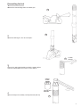
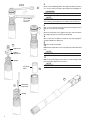
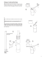
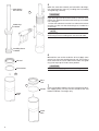
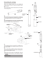
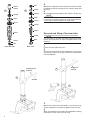
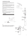
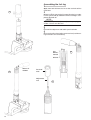
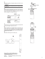
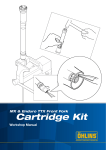
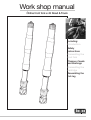
Work shop manual
Öhlins front fork ø 43 Road & Track
Including:
Introduction
Safety
instructions
Dismantling the
front fork
Change of seals
and bushings
Dismantling the
cartridge
Assembling the
fork leg
1
Before installation
Safety signals
Important information concerning safety is distinguished
in this manual by the following notations:
The Safety alert symbol means:
Caution! Your safety is involved.
Öhlins Racing AB can not be held responsible for any damage whatsoever to shock absorber or vehicle, or injury to
persons, if the instructions for fitting and maintenance are
not followed exactly.
Similarly, the warranty will become null and void if the instructions are not adhered to.
WARNING!
WARNING!
Failure to follow warning instructions could result in
severe or fatal injury to anyone working with, inspecting or using the suspension, or to bystanders.
CAUTION!
Caution indicates that special precautions must be
taken to avoid damage to the suspension.
NOTE!
This indicates information that is of importance with
regard to procedures.
1. Installing a shock absorber, that is not approved by the
vehicle manufacturer, may affect the stability of your vehicle. Öhlins Racing AB cannot be held responsible for any
personal injury or damage whatsoever that may occur after
fitting the shock absorber. Contact an Öhlins dealer or other
qualified person for advice.
2. Please study and make certain that you fully understand
all the mounting instructions and the owners manuals before handling this shock absorber kit. If you have any questions regarding proper installation procedures, contact an
Öhlins dealer or other qualified person.
3. The vehicle service manual must be referred to when
installing the Öhlins shock absorber
Öhlins products are subject to continual improvement and
development. Consequently, although these instructions
include the most up-to-date information available at the
time of printing, there may be minor differences between
your suspension and this manual. Please consult your
Öhlins dealer if you have any questions with regard to the
contents of the manual.
NOTE!
During storage and transportation, especially at high ambient temperature, the oil and grease used for assembling
may run out inside the packing and damage the expanded
polystyrene packing material. This is not unusual and is in
no way detrimental to the shock absorber.
Contents
Dismantling the fork ______________________________ 3
Change of seals and bushings _____________________ 5
Dismantling the cartridge __________________________ 7
Removal and fitting of the inner tube ________________8
Assembling the cartridge __________________________ 9
Assembling the fork leg _________________________ 10
Maintenance and inspection _____________________ 11
© Öhlins Racing AB.
All rights reserved.
Any reprinting or unauthorized use
without the written permission of
Öhlins Racing AB is prohibited.
Printed in Sweden.
2
Dismantling the fork
1
Remove the front fork legs from the motorcycle.
1
2
2
Fasten the fork leg in a vice. Use soft jaws.
3
17 mm
wrench
3
Loosen the spring pre-load by turning the upper adjustment nut counter clock vise. Use a 17 mm wrench.
24 mm
socket
Top nut tool
0797-04
4
Loosen the top nut assembly. Use Top nut tool (797-04)
4
3
5
17 mm
wrench
Let the outer tube drop down. Use Top nut holder (4705-01)
or a 17 mm wrench to keep a firm hold of the cartridge nut.
5
CAUTION!
Beware not to damage the O-ring.
NOTE!
Tool 4705-01
or 17 mm
wrench
When a standard 17 mm wrench is used, the upper spring
seat must be pressed down, to make access to the nut.
6
6
Use a 17 mm wrench to loosen the top nut and remove the
top nut assy from the cartridge.
7
Unscrew and remove the upper nut of the shaft to release
the upper spring seat and the pre load tube.
8
Use a steel wire shaped to a hook in one end to grip the
spring and pull the spring out.
9
Remove the pre-load tube.
7
10
Upper nut
Free the front fork from the vice and pour the front fork fluid
out.
Upper
spring nut
The adjustment rod must be held in position not to fall out.
NOTE!
11
Put the front fork leg back into the vice and carefully slide
the outer tube upwards to remove it.
Spring
NOTE!
Use a cloth to avoid excess oil from trickling out from the tube.
Pre-load
tube
9
10
8
Steel wire
with hook
Spring
4
Change of seals and bushings
1
Dust seal
Tool
4705-01
Remove the dust seals with a flat tool, i.e. the other side of
the top nut holder (4705-01). Use a piece of cloth under the
tool to prevent it from damaging the end of the outer tube.
1
2
Use a small flat tip screwdriver to remove the oil seal clip.
3
Remove the oil seal in the same way the dust seal was
removed. Remove the seat washer beneath the seal.
Oil seal clip
4
Use a heat gun to warm up the outer tube to a temperature
of approximately 100°C. Remove the bushings. This is made
with the use of attachment bar (1757-01), dismantling sleeve
(1759-07) and a hammer. The tool is inserted from the bottom of the tube.
2
4
Attachment bar
1757-01
Oil seal
Heat
gun
3
Seat washer
Dismantling
sleeve
1259-07
5
5
Clean the outer tube carefully and reinstall the bushings.
Use attachment bar (1757-01), installing sleeve (1759-08)
and guide ring (1758-04).
Attachment
bar 1757-01
5
CAUTION!
Be careful to get the bushings straight and do not push the
upper bushing too far down into the tube, as that can cause
malfunction. Heat the tube before the bushings are installed.
Use a heat gun.
Put the outer tube back onto the inner tube and check the
function to make sure that the bushings are installed in a
correct way.
Guide ring
1758-04
NOTE!
Apply locking fluid Loctite 601 or similar to the outside of
the bushings before installing them into the outer tube.
Installing sleeve
1759-04
6
Reinstall the seat washer under the oil seal. Apply some
grease (147-01) to the outside of the oil seal. This makes it
much easier for the seal to slide into the tube. Use guide
ring (1758-04) to push it into correct position.
Oil seal
CAUTION!
Seat washer
Be careful not to apply grease into the sealing surface.
6
Dust
seal
7
7
Circlip
Outer
tube
Outer
tube
6
Put the circlip back and press the dust seal back into position. Apply grease (147-01) onto the outside of the seal
before installation. Use fingers only.
Dismantling the cartridge
1
Loosen the cartridge and pull it out. Use Cartridge tool
(4702-01) Pour the fluid out. Empty by sliding the piston
rod in and out.
1
2
Free the fork bottom and inner tube from the vice and pour
the remaining oil out.
Cartridge tool
4702-01
2
3
Use clamping tool (787-03) and reinstall the cartridge into
the vice. The clamping tool should be close to the base
valve. Approximately 20 mm from the cartridge end.
Cartridge
4
Use cartridge tool (04702-01) to loosen the spring seat cap
from the cartridge tube. As the cap is fixed with locking
fluid a heat air gun must be used to release it.
Inner tube
20 mm
Clamping tool
0787-03
3
4
Piston shaft
6
Cartridge tool
04702-01
5
Base
valve
Clamping tool
0787-03
7
5
Use clamping tool (787-03) and refit the cartridge into a
vice. The clamping tool should be positioned so that the
base valve is free.
6
Use a small, flat tip screwdriver to loosen the base (compression) valve. Pull the base valve out with a rotating movement, not to damage the o-rings.
7
Pull the piston shaft out from the cartridge tube. Take care
not damage seals and surfaces. Clean the parts carefully.
Cartridge tube
NOTE!
Use compressed air to remove excess fluid and particles
and to dry the parts.
7
Nut
Piston
holder
8
9
Collar
Remove the rebound valve from the piston rod. Disassemble
the rebound valve by removing the nut, washers, piston and
the shims.
9
Spring
Disassemble the base (compression valve) in a similar way.
Shim
When disassembling the rebound and compression valves it
is necessary to put the components on the working bench in
correct order to avoid mistakes in assembly work
Spring
Shim
8
NOTE!
Piston
Piston
O-ring
Shims
Shims
Removal and fitting of the inner tube
Collar
Collar
Bolt
NOTE!
This procedure is normally only performed when the inner
tube or the fork bottom has been damaged and has to be
replaced.
Nut
Rebound valve
Base valve
1
Fasten the inner tube to the vice.
2
Remove the inner tube from the fork bottom. Use of clamp
tool (786-05) and a heat air gun to release the fork bottom
from locking fluid.
Clamping tool
0786-05
Clamp tool
0786-05
2
3
200 Nm
1
3
Refit the inner tube to the fork bottom. Use Loctite 270 or
similar and tighten to a torque of approximately 200 Nm.
4
When reinstalling the inner tube to the fork bottom, locking
fluid Loctite 270 or similar must be used.
8
Assembling the cartridge
1
Clean all parts of the base valve and rebound valve carefully and assemble them in correct order. Tighten the nuts
to correct torque: 8 Nm.
20 mm
2
Put a new O-ring onto the compression piston. Reinstall
the base (compression) valve into the cartridge case. Use
grease (147-01) and push it into position with a rotating
movement, to avoid damaging the o-ring.
3
3
Use clamping tool (787-03) and put the cartridge tube back
into the vice. The clamp tool should be positioned around
the base valve seat.
4
Put a new piston ring onto the rebound piston. Apply
grease (147-01) to the valve and push the piston rod into
the cartridge case.
5
4
Apply some Loctite 270 or similar to the spring seat cap.
Screw the spring seat cap (seal head) back. Use cartridge
tool (4702-01) and tighten it to 40 Nm.
CAUTION!
It is of great importance to use a torque wrench.
Spring
seat
5
Cartridge
tube
Cartridge tool
04702-01
6
Insert the cartridge tube into the inner tube. Apply some
grease (147-01) to the tread going into the fork bottom and
tightenit to a torque of 40 Nm. Use a torque wrench.
6
Cartridge tool
4702-01
Inner tube
40 Nm
Outer tube
9
Assembling the fork leg
1
Apply front fork fluid onto the inner tube and reinstall the
outer tube.
1
2
Fill 500 ml Öhlins front fork oil (1309-01)into the inner tube.
Push the piston rod up and down until the cartridge is completely filled with oil.
NOTE!
Open the compression adjuster fully before pumping procedure. Use a 3 mm allen tool
3
Reinstall the adjustment rod and the pre-load tube.
4
Measure the oil level and adjust to correct level (see Mounting instructions for correct data).
See
Owners
manual
Oil level
500 ml oil
1309-01
2
Pre-load
tube
Adjustment
rod
10
3
4
5
Reinstall the spring, the upper spring seat and the nut of
the piston rod.
Nut
NOTE!
Upper spring
seat
The spring is to be positioned with the marking number
facing upward.
6
Pull the piston rod upwards and screw it into the top nut
assy. Use Top nut holder (4705-01) or a 17 mm wrench to
keep a firm hold of the cartridge nut and use a 17 mm
wrench to tighten to a torque of 20 Nm.
5
Spring
17 mm
wrench
6
4705-01
or
17 mm wrench
7
Put the top nut assy back into the fork leg. Use top nut tool
(797-04) and tighten it gently by hand.
8
7
Adjust compression and rebound by first turning the adjusters clock vise to 0-position. Then turn them counter
clock vise to correct number of clicks according to Mounting instructions or Specification card. Set the pre-load according to specifications.
9
Reinstall the fork legs to the motorcycle.
9
Inspection and maintenance
For optimal performance:
Racing
Street use
50 hours (hard riding, shorter intervals)
10,000 km
11
More info
www.ohlins.com
Öhlins Racing AB, Box 722, S-194 27 Upplands Väsby, Sweden
Phone +46 8 590 025 00, Fax +46 8 590 025 80
12
07640-02, Teknisk Illustration, WSM 05 03.
The ultimate suspension site.
Find out everything about your suspension.
Download mounting instructions, manuals and brochures.
And a lot more.