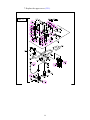
1
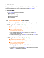
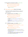
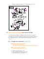
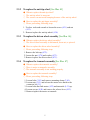
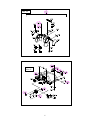
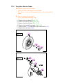
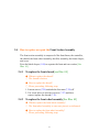
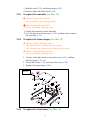
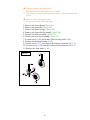
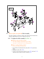
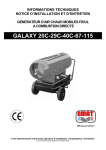
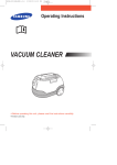
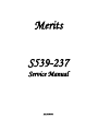
Merits S539-237 Service Manual Jan.27.2010V1 Index Introduction ...................................................................................... P1 Service Guide .................................................................................... P1 2.1. How to replace or repair the Seat Assembly ...........................................P1 2.1.1. To replace the seat body........................................................................................... P1 2.1.2. To replace the armrest assembly............................................................................... P1 2.1.3. To replace the seat base plate assembly .................................................................... P3 2.2. How to replace or repair the Battery Pack Assembly............................. P5 2.2.1. To replace the lower cover assembly ........................................................................ P3 2.2.2. To replace the upper cover assembly ........................................................................ P3 2.3. How to replace or repair the Rear Section Assembly ............................. P4 2.3.1. To replace the rear shroud ........................................................................................ P5 2.3.2. To replace the anti-tip wheel .................................................................................... P5 2.3.3. To replace the driven wheel assembly ...................................................................... P5 2.3.4. To replace the transaxle assembly ............................................................................ P5 2.3.5. To replace the rear frame ......................................................................................... P7 2.4. How to replace or repair the Front Section Assembly ............................ P8 2.4.1. To replace the front shroud ...................................................................................... P8 2.4.2. To replace the front wheel assembly ........................................................................ P8 2.4.3. To replace the controller .......................................................................................... P8 2.4.4. To replace the frame clasper .................................................................................... P9 2.4.5. To replace the front frame ........................................................................................ P9 2.5. How to replace or repair the Tiller Assembly .........................................P11 2.5.1. To replace the tiller assembly................................................................................... P11 2.5.2. To remove the lower cover ....................................................................................... P11 2.5.3. To replace the throttle lever or variable resistance .................................................... P11 2.5.4. To replace the horn button or buzzer ........................................................................ P12 2.5.5. To replace the power indicator ................................................................................. P12 2.5.6. To replace the knob or potentiometer ....................................................................... P12 2.5.7. To replace the key and key switch ............................................................................ P12 2.5.8. To replace the lower cover ....................................................................................... P13 The numbers shown in this service manual is just for reference. The part numbers should be in accordance with current exploded drawing 1. Introduction The purpose of this manual is to provide dealers and/or distributors with the product information and instructions that are required for servicing the S237 scooter. 2. Service Guide The S237 scooter consists of five main parts: Seat Assembly Battery Pack Assembly Rear Section Assembly Front Section Assembly Tiller Assembly 2.1 How to replace or repair the Seat Assembly The seat assembly includes the seat body and the seat base plate assembly. 2.1.1 To replace the seat body [See Illus. 01] ◆ When to replace the seat body? ◇ The seat body is worn out, pierced, scratched, or out of shape. ◆ How to replace the seat body? ◇ Please proceeding following steps. 1. Push down the seat free bar (4.08) to release the seat assembly (4.1) from the frame and pull it out. 2. Use hex tools to loosen four screws (4.03) on seat base plate (4.02) and remove the seat body (4.01). 2.1.2 To replace the armrest assembly [See Illus. 02] When to replace the armrest assembly? ◇ The armrest is worn out, pierced, scratched, or out of shape. ◆ How to replace the armrest assembly? ◇ Please proceeding following steps. 1. Use hex. tools to loosen the screws (4.05) and then take the armrest assembly (4.F) out. 2. Use screwdriver to loosen the screw (4.73) under armrest to disassemble armrest (4.72) from armrest support plate. 1 Illus. 01 Illus. 02 2 2.1.3 To replace the seat base plate assembly [See Illus. 01&02] ◆ When to replace the seat base plate assembly? ◇ The seat base plate is deformed or out of shape. ◆ How to replace the seat base plate assembly? ◇ Please proceeding following steps. Please See 2.1.1& 2.1.2 2.2 How to replace or repair the Battery Pack Assembly The battery pack assembly is composed of the lower cover, upper cover, handle, charger socket set, circuit breaker, two batteries, multi electric harnesses, and so on. 2.2.1 To replace the lower cover assembly [See Illus. 03] When to replace the lower cover or related parts? ◇ If the lower cover or battery is worn out or broken. ◆ How to replace the lower cover or relation parts? ◇ Please proceeding following steps. 1. Use screwdriver to loosen 8 screws (9.42) to open the cover assembly. 2. Unplug the harness (9.41), loosen nut (9.38), and then remove the conducts (9.37). 3. Remove/replace the battery (9.40) and replace the lower cover (9.33). 2.2.2 To replace the upper cover assembly [See Illus. 03] When to replace the upper cover or related parts? ◇ The upper cover, circuit breaker, charger socket set, or handle is worn out or broken. ◇ If the circuit breaker can not reset or broken. ◆ How to replace the upper cover or relation parts? ◇ Please proceeding following steps. 1. Take the battery pack assembly out and separate the upper and lower covers [See 2.2.1]. 2. Loosen the circuit breaker cap (9.23) by hand. Remove/replace the circuit breaker (9.22). 3. Use screwdriver and wrench to loosen the screw (9.28) and nut (9.30), and then remove/replace the charger socket set (9.27). 4. Use screwdriver to loosen screws (9.32). 3 5. Remove/replace the handle (9.31) or the upper cover (9.21). Illus. 03 2.3 How to replace or repair the Rear Section Assembly The rear section assembly is composed of the rear frame, the transaxle assembly, the rear wheel assembly, the fender, the anti-tip wheel, and so on. Press the black clasper (1.09) to separate the front and rear section. [See Illus.10] 2.3.1 To replace the rear shroud [See Illus. 04] ◆ When to replace the rear shroud? ◇ The rear shroud is out of shape. ◇ The scooter can not avoid bumping because of the broken fender. ◆ How to replace the rear shroud? ◇ Please proceeding following steps. 1. Remove the plastic plug (7.67). 2. Use screwdriver to loosen screws (7.64). 3. Remove/replace the rear shroud (7.5). 4 2.3.2 To replace the anti-tip wheel [See Illus. 05] ◆ When to replace the anti-tip wheel? ◇ The anti-tip wheel is worn out. ◇ The scooter can not avoid bumping because of the anti-tip wheel. ◆ How to replace the anti-tipper assembly? ◇ Please proceeding following steps. 1. Use hex. tools and wrench to loosen the screw (4.31) and nut (4.33). 2. Remove/replace the anti-tip wheel (4.30). 2.3.3 To replace the driven wheel assembly [See Illus. 06] ◆ When to replace the driven wheel assembly? ◇ The driven wheel assembly is deformaed, worn out, or pierced. ◆ How to replace the driven wheel assembly? ◇ Please proceeding following steps. 1. Remove the hub cap (4.72). 2. Loosen the nut (4.74) and washer (4.73). 3. Remove/replace the driven wheel (4.71). 2.3.4 To replace the transaxle assembly [See Illus. 07] ◆ When to replace the transaxle assembly? ◇ There is noise on transaxle assembly. ◇ The transaxle assembly is not working properly. ◆ How to replace the transaxle assembly? ◇ Please proceeding following steps. 1. Loosen bolts (3.81) and remove mounting clamp (3.80). 2. Loosen nuts (3.15) and release the motor wire attach to the connector kit (3.1) 3. Loosen bolts that link motor (4.52) and transaxle (4.51) up. 4. Loosen screws (4.54) and remove the release lever (4.53). 5. Remove/replace the motor or transaxle. 5 Illus. 04 Illus. 05 6 2.3.5 To replace the rear frame When to replace the rear frame? ◇ If the rear frame is deformed or out of shape. ◇ The scooter can not avoid bumping because of the deformed rear frame. How to replace the rear frame? ◇ Please proceeding following steps. 1. 2. 3. 4. 5. 6. Remove the rear shroud. [See 2.3.1] Remove the anti-tip wheel. [See 2.3.2] Remove the driven wheel. [See 2.3.3] Remove the transaxle assembly. [See 2.3.4] Loosen screws (3.16) and remove the connector kit (3.1). Replace the rear frame (3.01). Illus. 06 Illus. 07 7 2.4 How to replace or repair the Front Section Assembly The front section assembly is composed of the front frame, the controller, the shroud, the front wheel assembly, the tiller assembly, the frame clasper, and so on. Press the black clasper (1.09) to separate the front and rear section. [See Illus. 10] 2.4.1 To replace the front shroud [see Illus. 08] ◆ When to replace the shroud? ◇ The shroud is broken. ◆ How to replace the shroud? ◇ Please proceeding following steps. 1. Loosen screws (7.29) and take the foot matt (7.28) off. 2. Use screw driver to loosen six screws (7.27) and then remove/replace the shroud (7.21). 2.4.2 To replace the front wheel assembly [See Illus. 09] When to replace the front wheel assembly? ◇ The front wheel assembly is worn out, pierced, or deformed. ◆ How to replace the front wheel assembly? ◇ Please proceeding following steps. 8 1. Hold the screw (3.03) and loosen the nut (3.05), 2. Remove/replace the front wheel (3.02). 2.4.3 To replace the controller [see Illus. 10] ◆ When to replace the controller? ◇ The controller is not working properly. ◆ How to replace the controller? ◇ Please proceeding following steps. 1. Unplug all connectors on the controller. 2. Use screwdriver to loosen screws (1.39), and then remove/replace the controller (1.38). 2.4.4 To replace the frame clasper [See Illus. 10] When to replace the frame clasper? ◇ The frame clasper is deformed or out of shape. ◇ The front and rear section can not link together securely. How to replace the frame clasper? ◇ Please proceeding following steps. 1. Use hex. tools and wrench to loosen the screw (1.12), and then take the spring (1.11) out. 2. Loosen the screws (1.10) and remove the cover (1.09). 3. Replace the frame clasper (1.08). Illus. 08 2.4.5 To replace the front frame [See Illus. 10] 9 When to replace the front frame? ◇ The front frame is deformed or out of shape. ◇ The scooter can not avoid bumping because of the deformed front frame. How to replace the front frame? ◇ Please proceeding following steps. 1. Remove the front shroud. [See 2.4.1] 2. Remove the controller. [See 2.4.2] 3. Remove the frame clasper. [See 2.4.3] 4. Remove the front wheel assembly. [See 2.4.4] 5. Remove the tiller assembly. [See 2.5.1] 6. Romove the seat post assembly. [See 2.1.1] 7. Loosen screw (1.06) and remove tiller steering lock (1.04). 8. Remove the headset bearing (1.02). 9. Loosen screws (1.37) and remove the battery connector kit (1. 3). 10. Loosen screws (1.26) and then remove front connector kit (1.2). 11. Replace the front frame (1.01). Illus. 09 10 Illus. 10 2.5 How to replace or repair the Tiller Assembly The tiller assembly is composed of tiller, upper shroud, lower shroud, horn, indicator light throttle lever, power indicator, and so on . 2.5.1 To replace the tiller assembly [See Illus. 11] ◆ When to replace the tiller assembly? ◇ The tiller assembly is deformed or out of shape. ◇ Any part of control panel is not working properly. ◆ How to replace the tiller assembly? ◇ Please proceeding following steps. 1. Cut off all ties that bind the tiller main cable (5.80) on the front frame. 2. Unplug the main cable (5.80). 3. Use hex. tools and wrench to loosen screws (5.12) and nuts (5.14), and then remove/replace the tiller assembly (5.0). 11 2.5.2 To replace the lower cover [See Illus. 11] ◆ When to replace the lower cover (5.79)? ◇ The lower cover is broken. ◆ How to replace the lower cover? ◇ Please proceeding following steps. 1. Use screwdriver to loosen 6 screws (5.81), and then separate the upper shroud and lower cover assembly. 2. Unplug the connector which connect main cable (5.80) of tiller and control cable (5.64), and then remove/replace the lower cover. 2.5.3 To replace the throttle lever or variable resistance [See Illus. 11] ◆ When to replace the throttle lever (5.75) or variable resistance (5.66)? ◇ The throttle lever or variable resistance is not working properly. ◆ How to replace the throttle lever and variable resistance? ◇ Please proceeding following steps. 1. Use hex. tools to loosen the set screw (5.76) 2. Remove/replace the throttle lever (5.75) 3. Loosen set screws (5.71) 4. Remove throttle lever spring set (5.70) and torsion spring (5.69) 5. Loosen the nut (5.68) and screws (5.73) 6. Remove mounting plate (5.67) and then replace variable resistance (5.66). 2.5.4 To replace the horn button or buzzer [See Illus. 11] ◆ When to replace the horn button (5.58) and buzzer (5.59)? ◇ The horn button or buzzer is not working properly. ◆ How to replace the horn button and buzzer? ◇ Please proceeding following steps. 1. Loosen the nut on horn button (5.58) 2. Remove/replace the horn button. 3. Loosen screws (5.60) and then remove/replace the buzzer (5.59). 2.5.5 To replace the power meter [See Illus. 11] ◆ When to replace the power meter? ◇ The power indicator is not working properly. ◆ How to replace the power meter? 12 ◇ Please proceeding following steps. 1. Unplug the cable of the power meter (5.55). 2. Loosen screws (5.57) and then remove the clamp (5.56). 3. Remove/replace the power meter (5.55). 2.5.6 To replace the knob or potentiometer [See Illus. 11] ◆ When to replace the knob or potentiometer? ◇ The knob or potentiometer is not working properly. ◆ How to replace the knob or potentiometer? ◇ Please proceeding following steps. 1. Loosen nut on knob (5.54). 2. Remove/replace the knob or potentiometer (5.62). 2.5.7 To replace the key or key switch [see Illus. 11] ◆ When to replace the key or key switch? ◇ The key or key switch is not working properly. ◆ How to replace the key or key switch? ◇ Please proceeding following steps. 1. Pull the key (5.63) out. 2. Lossen the nut on the key switch (5.53). 3. Remove/replace the key or key switch. 2.5.8 To replace the upper cover [See Illus. 11] ◆ When to replace the upper cover? ◇ The upper cover is broken. ◆ How to replace the upper cover? ◇ Please proceeding following steps. 1. Separate the lower and upper cover. [See 2.5.2] 2. Remove the throttle lever and variable resistance. [See 2.5.3] 3. Remove the horn button and buzzer. [See 2.5.4] 4. Remove the power indicator. [See 2.5.5] 5. Remove the knob and potentiometer. [See 2.5.6] 6. Remove the key and key switch. [See 2.5.7] 13 7. Replace the upper cover (5.51). Illus. 11 14