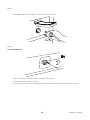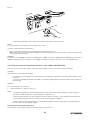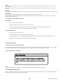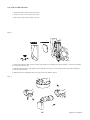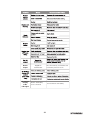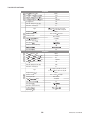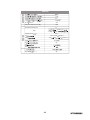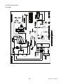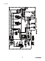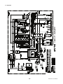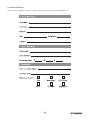
1
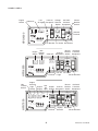
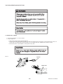
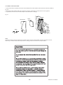
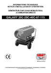
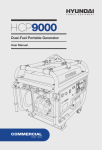
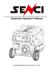
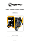
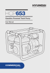
PRINTSPEC: EN505-2010v1
© 2010 MIDLAND INTERNATIONAL INC.
PREFACE
Thank you for purchasing a Hyundai Professional generator.
Please register your product in order for us to ensure your continuous satisfaction with our product.
This manual covers the safety, operation and maintenance procedures for the HPG4000, HPG6500 and HPG7500 models.
All information in this publication is based on the latest product information available at the time of approval for printing.
No part of this publication may be reproduced without written permission.
If a problem should arise, please contact us by using the contact information at the end of this manual.
It is important that this manual be fully read and understood before operating the generator set. Failure to do so may cause serious injuries or equipment damage.
CONTENTS
1.0 SAFETY PRECAUTIONS.......................................................................................................................................
1.1
Safety Labels.......................................................................................................................................
1.2
Operations Safety .............................................................................................................................
1.3
AC Safety Guidelines ........................................................................................................................
1.4
Maintenance Safety ..........................................................................................................................
1.5
Other Safety Hazards ........................................................................................................................
5
5
5
5
6
6
2.0 IDENTIFICATIONS OF COMPONENTS ...............................................................................................................
7
3.0 PRE-OPERATION .................................................................................................................................................
3.1
Engine Oil Check ..............................................................................................................................
3.2
Fuel Level Check ...............................................................................................................................
3.3
Check Air Filter ..................................................................................................................................
10
10
11
12
4.0 OPERATION .........................................................................................................................................................
4.1
Mounting Instructions .......................................................................................................................
4.2
Electric Start Battery Connection .....................................................................................................
4.3
Starting the Generator Set ................................................................................................................
4.4
Using the Generator Set ...................................................................................................................
4.5
Using DC Output Terminals ..............................................................................................................
4.6
Stopping the Generator Set...............................................................................................................
13
13
16
17
21
23
24
5.0 MAINTENANCE ....................................................................................................................................................
5.1
Importance of Maintenance ..............................................................................................................
5.2
Maintenance Schedule .....................................................................................................................
5.3
General Inspection ............................................................................................................................
5.4
Air Filter Service ................................................................................................................................
5.5
Sediment Cup Service ......................................................................................................................
5.6
Changing Engine Oil .........................................................................................................................
5.7
Spark Plug Service ............................................................................................................................
5.8 Handling and Storage .......................................................................................................................
24
24
24
25
26
27
27
28
29
6.0 TROUBLESHOOTING .......................................................................................................................................... 30
7.0 SPECIFICATIONS AND DATA ............................................................................................................................... 32
8.0 WIRING DIAGRAMS.............................................................................................................................................. 34
9.0 WARRANTY .......................................................................................................................................................... 37
10.0 GLOSSARY ......................................................................................................................................................... 38
11.0 QUESTIONNAIRE ............................................................................................................................................... 39
12.0 NOTES ................................................................................................................................................................ 42
1.0 SAFETY PRECAUTIONS
1.1 SAFETY LABELS
1.2 OPERATIONS SAFETY
•
•
•
•
•
•
•
•
•
•
•
•
•
•
•
•
•
Always perform a pre-operation check before starting the engine.
Properly clean and maintain the equipment.
Operate the generator according to instructions for safe and dependable service.
Before operating the generator, read the user manual carefully. Otherwise, it may result in personal injuries or equipment damage.
Never run the generator in an enclosed area to avoid harm from exhaust emissions of a poisonous carbon monoxide gas.
Be careful not to touch the exhaust system during operation because it can cause burns.
Pay attention to the warning labels because the engine exhaust system will become heated during operation and remain hot immediately after the engine is stopped.
Gasoline is a highly flammable and explosive liquid. Refuel in a well ventilated area with the engine stopped.
When refueling the generator, keep it away from cigarette, open flames, smoke and/or sparks.
Connections for standby power to a building’s electrical system must be done by a qualified electrician and must comply with all applicable laws and electrical codes. Improper connections may cause serious injuries to electrical workers dur-
ing a power outage, and when the utility power is restored, the generator may explode or causefires.
Place the generator at least 3ft away from buildings or other equipment during operation.
Run the generator on a level surface. If the generator tilts fuel spillage may result.
Know how to stop the generator quickly and understand operation of all the controls. Never permit anyone to operate the generator without proper instructions.
Keep children, pets and rotating parts away from the generator during operation.
Do not operate the generator in rain or snow.
Do not allow any moisture to come in contact with the generator.
Do not touch the spark plug while the generator is operating and shortly after the generator has been shut down
1.3 AC SAFETY GUIDLINES
Before connecting the generator to an electrical device or power cord:
•
•
•
•
Make sure that everything is in right working order. Faulty devices or power cords can lead to an electrical shock.
Turn off the generator immediately if the device begins to operate abnormally. Then disconnect the device and investi-
gate the problem.
Make sure that the electrical rating of the device does not exceed that of the generator. If the power level of the device is between the maximum output power and the running power of the generator, the generator should not be used for more than 30 minutes.
The connections from the generator to the household power supply should be done by professional electrical techncians.
Improper connections may lead to a fire hazard or damages to the generator set.
5
1.4 MAINTENANCE SAFETY
•
•
•
•
•
•
•
•
•
•
After any maintenance is performed, wash your body immediately using soap and clean water because repeated exposure to
lubricant may cause skin irritation.
Do not clean the filter element with flammable liquids like gasoline because explosion may occur.
Turn off the generator set before performing any maintenance. Otherwise it can cause severe personal injury or death.
Allow the generator set to cool down before performing any maintenance.
Always wear safety glasses when cleaning the generator set with air.
Do not clean the generator set with a pressure washer because it can cause damage to the generator set.
Before working with batteries, ventilate the area, wear safety glasses, do not smoke and always disconnect the negative cable
first and reconnect it last.
Use rubber gloves when coming into contact with engine oil.
Always stop the generator set before removing the oil filler cap.
Only qualified maintenance personnel with knowledge of fuels, electricity, and machinery hazards should perform maintenance
procedures.
1.5 OTHER SAFETY HAZARDS
•
•
To avoid breathing in poisonous carbon monoxide from the exhaust gases, adequate ventilation should be provided if the generator set is running in a partially enclosed space.
If the generator set is stored outdoors, check all the electrical components on the control panel before each use. Moisture can
damage the generator and can lead to an electric shock.
6
HPG Series User Manual
2.0 IDENTIFICATION OF COMPONENTS
Carburetor
7
PANEL LABELS
Engine
Switch
Low
120V AC Voltage 120/240V
Oil Light Receptacle Selector Twistlock
Switch Receptacle
Voltmeter
Master
Breaker
Switch
VOLTAGE SELECTOR
ON
SÉLECTEUR DE TENSION
MARCHE
MASTER BREAKER
INTERRUPTEUR PRINCIPAL
ON
MARCHE
LOW OIL
Ground
Terminal
HUILE BAS
OFF
HPG4000
120V
VOLTMETER
ARRET
VOLTMÈTRE
ENGINE START
DÉMARRAGE DU MOTEUR
AC BREAKER
OFF
ARRET
DC BREAKER
SYSTEM FLOATING
INTERRUPTEUR CA
ON
MARCHE
120V/
240V
ON
MARCHE
OFF
ARRET
OFF
ARRET
DISJONCTEUR CC
SYSTÈME FLOATING
HPG
G
-
120V 20A AC/CA
12V 8A DC/CC
+
120V/240V 30A AC/CA
4000W 3250W
RUNNING POWER
MAXIMUM POWER
FORCE MAXIMALE
PUISSANCE DE
FONCTIONNEMENTNT
AC Breaker DC Outlet DC Breaker
Idle
Engine Control
Switch Switch
Master 120/240V
120V AC Breaker Twistlock
Receptacle Switch Receptacle
Voltmeter
A
VOLTMETER
B
MASTER BREAKER
ON
MARCHE
OFF
HPG6500
ON
MARCHE
OFF
ARRÊT
OFF
ARRÊT
ARRÊT
ENGINE START
IDLE-CONTROL
AC 120V
CA 120 V
CONTR Ô LE DE MISE
EN VEILLE
DÉMARRAGE DU MOTEUR
Idle
Control
Switch
C
INTERRUPTEUR PRINCIPAL
VOLTMÈTRE
ON
MARCHE
20A
A
DC 12V
CC 12 V
B
8A
LOW OIL
CIRCUIT BREAKERS
ON
MARCHE
HPG
G
MAXIMUM POWER
FORCE MAXIMALE
Engine
Switch
PUISSANCE DE FONCTIONNEMENT
+
120V/240V
AC/CA
Low Oil DC Outlet
Light
Circuit Breakers
Ground
Terminal
RUNNING POWER
12V DC/CC
Master 120/240V
Low
Output Oil
Output 120V AC Breaker Twistlock
Display Light Display Receptacle Switch Receptacle
Light
Switch
OUTPUT DISPLAY
A
B
AFFICHAGE SORTIE
ON
-
120V 20A AC/CA
6500W 5750W
OFF
ARRET
DISJONCTEURS
HUILE BAS
ON
ON
MARCHE
MARCHE
MARCHE
OFF
OFF
OFF
MASTER BREAKER
INTERRUPTEUR PRINCIPAL
IGNITION
C
ON
MARCHE
HPG7500
LOW OIL
ALLUMAGE
ARRÊT
ARRÊT
ARRÊT
IDLE-CONTROL
LIGHTS
ENGINE START
CONTR Ô LE D E MISE
EN VEILLE
L U MIÈRES
OFF
ARRÊT
HUILE BAS
AC 120V
CA 120 V
DÉMARRAGE DU MOTEUR
A
B
A
C
ON
MARCHE
HPG
20A
DC 12V
CC 12 V
B
8A
CIRCUIT BREAKERS
DISJONCTEURS
OFF
ARRET
G
DISPLAY SELECTOR
SÉLECTEUR D’AFFICHAGE
7500W 6750W
MAXIMUM POWER
FORCE MAXIMALE
Ground
Terminal
RUNNING POWER
PUISSANCE DE FONCTIONNEMENT
8
120V 20A AC/CA
-
12V DC/CC
+
120V/240V
AC/CA
Display DC Outlet
Selector
Circuit Breakers
HPG Series User Manual
LABEL PLACEMENT
9
3.0 PRE-OPERATION INSPECTION
3.1 ENGINE OIL CHECK
1. Ensure the generator is on a level surface.
2. Inspect engine oil:
• Take out the oil ller cap and clean the dipstick.
• Check the oil level by reinserting the oil ller cap without rotating it. Remove the oil ller cap and examine the oil level. If the oil level is at or below the lower level, rell the oil to the upper limit mark. (10W30 Oil for all three models)
• Reinsert the oil ller cap and tighten securely. (Refer to Fig. 3.0)
Fig 3.0
Dipstick
Upperlevel
Lowerlevel
10
HPG Series User Manual
3.2 FUEL LEVEL CHECK:
•
•
Check the fuel level by reading the gauge or removing the fuel tank cap to visually check the level.
Refuel if level is too low. Tighten the fuel tank cap securely after lling (Refer to Fig. 3.1)
Fig 3.1
Low
High
NOTICE
When the oil level is low, the low oil light on the control panel will flash and the engine will automatically shut down. Then take off
the oil dipstick to check the oil level.
11
3.3 CHECK THE AIR FILTER
1. Loosen the knob and remove the air filter cover. Remove the air filter element and observe for cleanliness. (Refer to
Fig. 3.2)
2. Clean the air filter element with soap and water or solvent. Squeeze dry and then soak in clean engine oil.
3. Squeeze out all excess oil and reinstall. Replace the element if it is damage
Fig 3.2
Filtercover
Filter
element
Knob
NOTE:
Check the air filter using the maintenance schedule. Always inspect air filter before using the generator. Clean Air
Filter every 3 months or after 50hrs of operation according Section 5.4: Air Filter Service procedure.
12
HPG Series User Manual
4.0 OPERATION
4.1 MOUNTING INSTRUCTIONS
HPG4000 (Refer to Fig 4.1)
1. Attach the handle bar to the upper frame of the generator. Tighten the bolts (14) and nuts (7) to the upper frame of the
generator.
2. Attach the two peg stands to the bottom of the frame of the generator. Tighten the two bolts (6) and two nuts (7) to the
lower frame of the generator.
3. Place the two wheels (5) on the wheel axle (4) and then secure the wheels using the washer (8) and split pin (9) to the
wheel axle (4).
4. Attach the wheel axle (4) to the bottom of the generator frame. Align the bolts (6) with the holes on the bottom of the
generator and fasten tightly with the nuts (7) provided.
Fig 4.1
13
Parts List for HPG4000
Bolt M6 x 16
15
Anti-Sink Plate
1
HPG6500/HPG7500 (Refer to Fig 4.2)
1. Attach the handle bars to the middle of the generator frame where specied in (gure 4.2) Tighten the bolts (14) and nuts (7) to the upper frame of the generator.
2. Attach the two peg stands at the bottom of the frame of the generator. Tighten the two bolts (6) and two nuts (7) to the lower frame of the generator.
3. Place the two wheels (5) on the wheel axle (4) and then secure the washer (8) using the split pin (9) to the wheel axle (4).
4. Attach the wheel axle (4) to the bottom of the generator frame. Align the bolts (6) with the holes on the bottom of the generator and fasten tightly with the nuts (7) provided.
14
HPG Series User Manual
Fig 4.2
Parts List for HPG6500 and HPG7500
2
15
4.2 ELECTRIC START BATTERY CONNECTION (HPG7500 ONLY)
1. Connect the red cable with the positive terminal of the battery. Ensure the connection is secured by using the fastener at the battery terminal. Refer to Fig 4.3
2. Connect the black cable with the negative terminal of the battery. Ensure the connection is secured by using the fast-
ner at the battery terminal. Refer to Fig 4.3
Fig 4.3
c
NOTE: Be sure to connect the Electric Start Battery to the HPG7500 Generator set before operation. Failure to do so will cause
the Output Display and LED lights to function improperly.
16
HPG Series User Manual
Donotattempttoconnectcableswiththebatteryterminalswhileengineisrunning.
NOTE:
Disconnect the cables from the battery terminals while the HPG7500 generator set is in storage. Failure to do so may cause
complete discharge.
4.3 STARTING THE GENERATOR SET
GROUND TERMINAL (For HPG4000, HPG6500 and HPG7500)
Before using generator, a ground wire must be connected to the ground terminal.
Before using the ground terminal consult a qualied electrician.
Ground Terminal Symbol:
Recoil Start for HPG4000/HPG6500/HPG7500
1. Before starting the engine, do not connect the generator to the device.
2. Rotate the fuel valve lever to ON position (Vertical position). Refer to Fig. 4.4
Fig 4.4
3. If the engine is cold:
For HPG4000, move the choke lever to the left side to close the choke.
For HPG6500/HPG7500, pull the choke lever out to close the choke (Refer to Fig. 4.5 for HPG6500/HPG7500 and Fig. 4.6 for HPG4000).
17
Fig 4.5
Fig 4.6
4. For HPG4000, press the engine switch to the “ON” position. Refer to Fig. 4.7. For HPG6500, press the engine switch to the “ON” position. Refer to Fig. 4.7. For HPG7500, press the engine switch to “ON” position. Refer to Fig. 4.7
Fig 4.7
FOR HPG4000 (similar to HPG6500)
FOR HPG7500
5. You may turn on the LED light by pressing the LIGHT switch in Fig 4.7 to ON position for the better view of the front panel.
18
HPG Series User Manual
NOTE:
Do not leave LED lights ON for long periods of time as it may consume all of the battery power.
6. Grasp the recoil starter handle and pull it until the engine starts. Refer to Fig. 4.8 ineffective on the next startup.
Fig 4.8
7. After the engine warms up, push the choke lever back to the OPEN position.
8. You may turn on the Idle-Control switch to the ON position to save fuel consumption, while low load is applied to the HPG7500 generator set.
NOTE:
During warm-up period, keep the Idle-Control OFF until the engine reaches operating temperature. Otherwise the warm-up
periods are extended. Idle-Control is not effective for use with appliances that require only momentary power. So it is better to
leave the Idle-Control OFF if an appliance cycles ON and OFF frequently.
NOTE:
Do not use the choke if the engine is warm or if the air temperature is higher than 50°F (10°C).
Electric Start for HPG7500
1. Before starting the engine, do not connect the generator to the device.
19
2. Rotate the fuel valve to “ON” position (vertical position). Refer to Fig 4.9
Fig 4.9
ValveLever
OFF
ON
3. If the engine is cold, pull the choke lever out to close the choke. Refer to Fig 4.10
Fig 4.10
Choke
Open
Close
4. Push the engine switch to ON position until started, but the start time cannot be more than 5 seconds. Otherwise the alternator may be damaged. Refer to Fig 4.7
NOTE:
Do not try to electric start more than 3 times in one attempt. Failure to do so may damage the generator set.
5. Push the choke lever to the OPEN position as the engine warms up. The choke is used to provide the proper mixture
when the engine is cold. It can be opened and closed by operating the choke lever manually by moving the lever to the closed position to enrich the mixture for cold starting.
6. You may turn on the Idle-Control switch to the ON position to save fuel consumption, while low load is applied to the HPG7500 generator set.
NOTE:
Do not use the choke if the engine is warm or if the air temperature is higher than 50°F (10°C).
NOTE:
During warm-up period, keep the Idle-Control OFF until the engine reaches operating temperature. Otherwise the warm-up
periods are extended.
20
HPG Series User Manual
Idle-Control is not effective for use with appliances that require only momentary power. So it is better to leave the Idle-Control OFF
if an appliance cycles ON and OFF frequently.
4.4 USING THE GENERATOR SET
For HPG4000
1. Turn off the switches of the device before connecting to the generator.
2. Select the receptacles to be used by using the AC Voltage Selector. Refer to Fig. 4.11
Fig 4.11
3. Start the generator according to section 4.3.
4. If the 120V option of the selector switch is chosen, insert the plug of the device into the 120V 20A receptacle. Refer to
Fig. 4.12
Fig 4.12
If the 120V/240V option of the selector switch is chosen, insert the plug of the device into the 120V/240V receptacle. Refer to Fig. 4.13
21
Fig 4.13
5. Turn the Master Breaker to ON and turn on the device. Refer to Fig. 4.14
Fig 4.14
For HPG6500/HPG7500:
1. Turn off the switches of the device before connecting to the generator.
2. Start the generator according to section 4.3
3. Insert the plug of the device into the receptacle based on the voltage requirement of the device. Refer to Fig. 4.15
22
HPG Series User Manual
Fig 4.15
4. Lift the Master Breaker switch to ON position and turn on the device. Refer to Fig. 4.14
NOTE:
To stop the engine in an emergency, turn the engine switch “OFF”.
In order to maintain generator’s performance:
•
•
Always connect the generator to the ground terminal to prevent electrical shock.
Add the watt ratings of all the loads that the generator set will be powering at the same time. Make sure that total wattage will
not exceed the generator rating.
EXAMPLE:
A generator set rated 5000W can power two 1500W heaters, a 900W circular saw, a 500W drill and a 100W light at the same time
(4500W combined). However, to operate a second 900W saw, it will be necessary to disconnect one of the 1500 W heaters.
4.5 USING DC OUTPUT TERMINALS FOR ALL HPG SERIES GENERATORS
Note: You can use 12V 8.3A DC output to charge automotive batteries. Be sure to monitor the battery charge time.
CAUTION
Over-charge may cause explosion and injury
1. Connect the positive (red) terminal of the battery to the red (positive) terminal the 12V 8.3A DC Output Terminal on the front panel
2. Connect negative(black) terminal of the battery to the black (negative) terminal of the 12V 8.3A DC Output terminal on the front panel
CAUTION
Do not reverse polarity of connections
3.
Start the generator according to section 4.3
NOTE:
1. An explosive hydrogen gas is discharged through vent holes in the battery during charging. Do not allow sparks or open flames around the generator or battery during the charging process.
2. Electrolyte fluid can burn eyes and clothing. Be extremely careful to avoid any contact. If injured, wash the affected area immediately with large amounts of water and seek medical attention immediately.
3. When charging a large capacity battery or totally discharged battery, excessive current may force the DC breaker to turn off. In this case, use a battery charger.
Ground Fault Circuit Interrupter Receptacle
This receptacle is protected by the GFCI for protection against electrical shock.
23
NOTE:
Using the generator in rain, snow, or in water can lead to electrical shock. Always keep your generator dry and away from any
water sources.
Perform this test monthly to insure proper operation. If used outdoors unprotected from the weather, make sure to test before
each use.
Test Button
The test button should extend with a click. If the test button does not extend, take to an authorized GMC generator service center.
Reset Button
If the reset button extends during operation, unplug all appliances from the GFCI receptacle.
The reset button should be flush with the test button. If the reset button is not flush with the test button, take to an authorized
GMC generator service center.
4.6 STOPPING THE GENERATOR SET
For HPG4000
1. Turn off all the connected devices.
2. Allow the generator set run for a few minutes to cool down.
3. Stop the generator set by pressing the engine switch to the OFF position until the generator set stops.
4. Rotate the fuel valve back to the OFF position (horizontal position).
For HPG6500/HPG7500
1. Turn off all the connected devices.
2. Allow the generator set run for a few minutes to cool down.
3. Stop the generator set by pressing and holding the engine switch in the OFF position until the generator set stops.
4. Rotate the fuel valve back to the OFF position (horizontal position).
5.0 MAINTENANCE
5.1 IMPORTANCE OF MAINTENANCE
Proper maintenance is important because it will ensure safe, eco- nomical and trouble-free operation. It will also reduce air pollution. Improper maintenance may cause the generator to malfunction and can lead to serious injuries or death.
5.2 MAINTENANCE SCHEDULE
NOTE:
Some of these maintenance techniques can be dangerous and should be performed by atechnician.
For HPG4000/HPG6500/HPG7500:
In order to maintain good performance and extending the service life of the generator, period inspection and adjustments should
be done based on the following maintenance schedule:
24
HPG Series User Manual
5.3 GENERAL INSPECTION
1. Look for fuel leaks around the fuel tank, fuel hose, fuel valve and carburetor. Close the fuel valve and repair leaks im-
mediately.
2. Look and listen for exhaust leaks while the engine is running. Have all the leaks repaired before continuing operation.
3. Check for dirt and debris and clean as necessary
4. Check the engine oil level and add oil as necessary.
25
5.4) AIR FILTER SERVICE
1. Rotate the knob counterclockwise to release.
2. Lift the air cover to remove from the air unit.
3. Remove the foam element. Refer to Fig. 5.0
Fig 5.0
4. If the foam element is dirty, clean it in warm soapy water, rinse, and allow it to dry thoroughly, or clean in non-flamma-
ble solvent and allow to dry.
5. Drip the foam element in clean engine oil, then squeeze out all excess oil. The engine will smoke when started if too much oil is left in the filter.
6. Wipe dirt from the air filterunit and cover using a moist rag. Refer to Fig. 5.1
Fig 5.1
26
HPG Series User Manual
5.5 SEDIMENT CUP SERVICE
1. Rotate the fuel valve to “OFF” position.
2. Remove sediment cup and O ring.
4. After fully dried, remount the parts.
5. Rotate the fuel valve to “ON” and check for leakage.
3. Wash the cup with non-flammable solvent.
Fig 5.2
5.6 CHANGING ENGINE OIL
1. Place the generator is placed on a flat, level surface.
3. Stop engine.
4. Place oil pan or other container underneath the generator for holding oil.
5. Keep oil filler cap to avoid oil spray.
6. Use a wrench to remove the drain bolt and sealing washer.
2. Start engine and run until it gets warm.
7. Slowly unscrew and remove the oil filler cap.
8. Allow oil to completely drain into oil pan or container.
9. Use clean cloth to wipe around oil fill and drain plug to clean any dirt and debris.
10. Reinstall sealing washer and drain plug bolt.
11. Pour new engine oil into oil fill hole.
12. Check oil level.
13. Reinstall oil filler cap. Refer to Fig. 5.3 and Fig. 3.0
27
CAUTION
Usedmotoroilmaycauseskincancerifrepeatedlyleftin
contactwiththeskinforpro longedperiods.Washyourhands
withsoapandwaterassoonaspossibleafterhandling
usedoil.
Fig 5.3
OilFillerCap
Oil Drain Plug
5.7 SPARK PLUG SERVICE
1. Remove the spark plug cap.
2. Clean any dirt and debris from around the spark plug base.
3. Use a wrench to remove the spark plug. Refer to Fig. 5.4
Fig 5.4
4. Visually inspect the spark plug. Discard it if the insulator is cracked or chipped. Clean the spark plug with a brush if it is to be reused.
5. Measure the plug gap with a feeler gauge. The gap should be 0.7 to 0.8 mm (0.028 to 0.031 inch). Correct as neces-
sary by care- fully bending the side electrode. Refer to Fig. 5.5
28
HPG Series User Manual
Fig 5.5
6. Install the correctly gapped spark plug back into the original position.
5.8 HANDLING & STORAGE
Handling
1. Turn off the engine switch and the fuel valve when transporting the generator set.
2. Do not touch the generator until the fuel choke is in the OPEN position because the engine is warm.
3. Keep the generator at a level position in order to prevent spillage.
Storage
Before storing the generator set for an extended period:
1. Ensure that the storage area is free of excessive humidity and dust.
2. Drain the fuel tank and the carburetor.
Draining the Fuel Tank
1.Turn the engine switch off.
3. Empty the fuel tank using a siphon and an approved gasoline container.
2. Remove the fuel tank cap and the debris screen under the cap.
Draining the Carburetor
1.Turn the engine switch OFF.
2. Turn the fuel valve ON.
3. Position a suitable container under the carburetor drain screw to catch fuel; loosen the screw.
4. Allow fuel to drain completely into container. 5. Retighten drain screw. Refer to Fig. 5.6
29
Fig 5.6
Disconnecting Electric Start Battery
1. Disconnect red cable from the positive battery terminal.
2. Disconnect black cable from the negative battery terminal. Refer to Fig 4.3
3. Store the battery in a dry place and recharge it once a month. Do not store the battery in an excessively warm or cold place. (for HPG7500 only)
6.0 TROUBLESHOOTING
The following table is a troubleshooting guide for diagnosing the generator set. If these recommendations cannot solve the problem, please contact our service center.
30
HPG Series User Manual
No DC
output
No Output
Display
or No
LED lights
Tripped DC
circuit breaker
Disconnect battery, reset breaker and
have battery tested for shorts
Electric Start battery
is not connected
Connect Electric Start battery
31
7.0 SPECIFICATIONS
GENERATOR
HPG4000
Rat
requenc
Hz)
Rat
AC O
Pow
M
AC O
Pow
1-P
Rat
Pow
Factor
60Hz
4.0
W)
AC V
120/240
(V )
1.0
Max DC Output Power (W)
100
Rated DC Voltage (V)
12
P, Single cylinder forced air
cooling
roke OHV 25 deg tilt
Type
Displacemen
ENGINE
3.25
W)
3
208cc
)
Ignition model
Non-contac ransistor
Starting model
Recoil Start
M
O
rpm)
4.1/3600
Fuel tank capacit
17
Oil capacit
Duration of Runs (Hours)
Dry Weigh Kg)
56
GENERATOR
HPG6500
Rat
Rat
M
requenc
60Hz
Hz)
AC O
Pow
AC O
Pow
1-P
Rat
Pow
Factor
W)
W)
AC V
(V )
100
Rated DC Voltage (V)
12
P, Single cylinder forced air
cooling
roke, OHV 25 deg tilt
Type
ENGINE
120/240
1.0
Max DC Output Power (W)
Displacemen
5.75
6.5
3
389cc
)
Ignition model
Non-contac ransistor
Starting model
Recoil Start
M
O
rpm)
7.6/3600
Fuel tank capacit
25
Oil capacit
Duration of Runs (Hours)
Dry Weigh Kg)
94
32
HPG Series User Manual
GENERATOR
HPG7500
Rat
requenc
Hz)
Rat
A O
Pow
M
A O
Pow
1-P
Rat
Pow
Factor
60Hz
6.75
W)
7.5
W)
AC V
120/240
(V)
1.0
Max DC Output Power (W)
100
Rated DC Voltage (V)
12
P
cooling
Type
ENGINE
Displacemen
420cc
)
3
Non-contac ransistor
Ig
Star
M
cylinder forc
roke
Rec
O
rpm)
F
Star
ctr
8.2/3600
t
28
t
Dura
6
Dry Weigh Kg)
99
33
Start
8.0 WIRING DIAGRAMS
For HPG4000
34
HPG Series User Manual
For HPG6500
35
For HPG7500
36
HPG Series User Manual
9.0 WARRANTY
Canadian distribution of Hyundai portable generators are distributed in Canada by:
Midland International 26 Rd. Unit #2
Toronto, Ontario
M9W 5Z6 Canada
This product is warranted to be free of defects in material and workmanship for two years from date of purchase. This warranty
guarantees that any defective parts will be repaired or replaced at no cost, including diagnosis and replacement parts.
Limited Warranty Periods:
Commercial use: 1 year limited, parts and labor
This limited warranty begins at the initial time of retail purchase and covers manufacturerís defects caused by a defect in components or workmanship during the two (2) Year period. The war- ranty coverage is continual from the initial date of purchase and
does not restart at anytime under any circumstances. This limited warranty is valid for residential or recreational applications only
and only when the generator receives all necessary preventative maintenance as described in the Hyundai Generators Operation
Manual. The repair or replacement of a generator will take place within a reasonable period of time during normal business hours.
All repair and replacement parts shall be warranted for (90) days after the initial date of installation or purchase.
Limitation of Remedies and Disclaimers
Midland International Inc. disclaims any responsibility for loss of time or use of the generator in a recreational vehicle or any
vehicle in which the generator is installed, transportation, commercial loss, or any other incidental or consequential damage. Any
im- plied warranties are limited to the duration of this written warranty. THE FOREGOING LIMITED WARRANTY IS EXCLUSIVE
OF AND IN LIEU OF ALL OTHER WARRANTIES OF MERCHANTABILITY, FITNESS FOR A PARTICULAR PURPOSE AND OF ANY
OTHER WARRANTY WHETHER EXPRESS OR IMPLIED.
Consumable parts, such as oil or fuel filters, fuel cut off valve, brushes, fuel injection nozzle valve, lubricant, or ignition plug, are
not covered under this warranty. All expenses incurred in maintain- ing and replacing parts for generator shall fall on the purchaser. This warranty coverage does not include parts affected by ac- cident and/or collision, corrosion or rust, normal wear, incorrect fuel type or fuel contamination, use in an application for which the product was not intended, unauthorized service, or any
other misuse, neglect, incorporation or use of unsuitable attachments or parts. Damage to voltage regulators caused by failure to
ground, shorting or overloading will not be covered under this warranty. Under this Warranty, we do not have the obligation to bear
any transportation fees of any product to/from an authorized Warranty Center. Unauthorized alteration, installation or any cause
other than defects in material or workmanship of the product will not be covered under the warranty.
Exclusions
Not Covered by this Limited Warranty:
1) Normal engine/alternator wear.
2) Damage caused by lack of maintenance as described in the Hyundai manuals, or negligence by using improper or impure motor oil, coolant, or fuel.
3) Damage caused by accidents, improper installation or storage.
4) Damage caused by water ingestion, submersion, or external water damage.
5) Damage or non-performance caused by operation of the gen- erator set in a marine application.
6) Damage caused by operation with improper fuel, or at speeds, loads, conditions, or modifications contrary to pub- lished specifications.
7) Items not supplied by Hyundai, including, but not limited to; starting batteries, battery cables, external wiring, fuel lines, filters etc; (refer to exclusions).
8) Repairs made during the warranty period, without obtaining a case number from Hyundai.
Batteries supplied with any generator product should be consid- ered a bonus item and not covered by warranty. Batteries can be
damaged by shock, shorting terminals, heat, acid spillage and a number of other factors that cannot be controlled after they have
left our facility. It is the customer’s responsibility to take great care when handling a battery so no spillage of acid will occur and cause corrosion; damage caused by battery acid is not covered under this warranty.
Product Registration
Product registration is required for product support and warranty coverage.
The ownerís registration found in the user manual can be com- pleted and mailed. You can also register online at
www.hyundaipower.ca.
You should keep your receipt for proof of purchase.
37
Warranty Claim Procedure:
Warranty service must be performed by one of our authorized service dealers. If you feel your generator is malfunctioning due to a
defect or misuse, simply contact our customer support center for technical advice, a warranty claim or general information.
Do not return your generator to the place of purchase for repair.
MIDLAND INTERNATIONAL INC. SHOULD BE CONTACTED TO PROVIDE A CASE NUMBER BEFORE WARRANTY WORK CAN
BEGIN.
To obtain warranty service: Contact our customer support centre:
Toll free: 1-877-528-3772
E-mail: [email protected] Website: Hyundaipower.ca
10.0 GLOSSARY
Air Filter - It removes dust from engine intake air.
Carburetor - A device used to properly mix fuel and air in the correct proportions and delivering the mixture into the engineís
combustion chamber.
Choke Lever - It is used to provide proper starting mixture when the engine is cold. The choke lever must be pulled out to ON
posi- tion when starting a cold engine.
Circuit Breaker - It protects circuits from being damaged due to overload or short circuit by stopping the
the generator and device.
of electricity between
Dipstick - It seals off engine oil fill hole and is used for indicating the engine oil level.
Drain Plug - A plug that can be removed to allow the contents of the engine to be drained off.
Earth Ground Lug - It connects generator to ground wire for grounding protection.
Fuel Cock - A tap which can allow or restrict the flow of gasoline from the gas tank to the carburetor.
Fuel Valve - It controls flow of fuel from fuel tank to carburetor. Pilot Light - A small flame used to ignite gas at a burner.
Recoil Starter - A pull cord is attached to the engine and you pull the T-handle attached to the starter cord assembly to spin the
and start the engine.
Reset Switch - A switch which puts the configuration of a component back to its standard setting.
Sediment Cup - A cup for storing sediments.
Selector Switch - A switch that is used to select among alternatives.
Spark Plug - A device screwed into the combustion chamber of a spark.
38
HPG Series User Manual
11.0 QUESTIONAIRE
Please complete and mail the form below, or register online by visiting our website: www.hyundaipower.ca
39
40
HPG Series User Manual
Please Mail To:
Or Register Online At:
Midland International Inc.
Rd. Unit 2.
26
Etobicoke, Ontario
M9W 5Z6 Canada
www.hyundaipower.ca
41
12.0 NOTES
42
HPG Series User Manual
43
44
HPG Series User Manual
45