1
1ST PRINTING FEB. 01
DX TYPE
Owner’s Manual
SEGA ENTERPRISES, INC. USA
MANUAL NO. 420-6589-01
Warranty
Your new Sega Product is covered for a period of 90 days from the date of shipment. This certifies
that the Printed Circuit Boards, Power Supplies and Monitor are to be free of defects in workmanship or materials under normal operating conditions. This also certifies that all Interactive Control
Assemblies are to be free from defects in workmanship and materials under normal operating conditions. No other product in this machine is hereby covered.
Sellers sole liability in the event a warranted part described above fails shall be, at its option, to
replace or repair the defective part during the warranty period. For Warranty claims, contact your
Sega Distributor.
Should the Seller determine, by inspection that the product was caused by Accident, Misuse, Neglect, Alteration, Improper Repair, Installation or Testing, the warranty offered will be null and void.
Under no circumstances is the Seller responsible for any loss of profits, loss of use, or other damages.
This shall be the exclusive written Warranty of the original purchaser expressed in lieu of all other
warranties expressed or implied. Under no circumstance shall it extend beyond the period of time
listed above.
BEFORE USING THE PRODUCT, BE SURE TO READ THE FOLLOWING:
To maintain the safety:
To ensure the safe usage of the product, be sure to read the following before using the product. The following
instructions are intended for the users, operators and the personnel in charge of the operation of the product.
After carefully reading and sufficiently understanding the warning displays and cautions, handle the product
appropriately. Be sure to keep this manual nearby the product or elsewhere convenient for referring to it
when necessary.
Herein, explanations which require special attention are enclosed with dual lines. Depending on the potentially hazardous degrees, the terms of WARNING, CAUTION, etc. are used. Be sure to understand the
contents of the displays before reading the text.
Indicates that mishandling the
product by disregarding this
warning will cause a potentially
hazardous situation which can
result in death or serious injury.
Indicates that mishandling the product
by disregarding this caution will cause
a slight hazardous situation which can
result in personal injury and or material
damage.
For the sage usage of the product, the following pictographs are used:
Indicates “HANDLE WITH CARE.” In order to protect the human body an equipment, this
display is attached to places where the Owner’s Manual and or Service Manual should be referred
to.
Perform work in accordance with the instructions herein stated.
Instructions for work are explained by paying attention to the aspect of accident prevention. Failing to
perform work as per the instructions can cause accidents. In the case where only those who have technical expertise should perform the work to avoid hazardous situation, the instructions herein state that the
serviceman should perform such work.
Be sure to turn off power before working on the machine.
To prevent electric shock, be sure to turn off power before starting the work in which the worker touches
the interior of the product. If the work is to be performed in the power-on status, the Instruction Manual
herein always states to that effect.
Be sure to ground the Earth Terminal (this, however, is not required in the case where a power cord
with earth is used).
This product is equipped with the Earth Terminal. When installing the product, Connect the Earth Terminal to the “accurately grounded indoor earth terminal” by using an earth wire. Unless the product is
grounded appropriately, the user can be subject to electric shock. After performing repair, etc. for the
Control equipment, ensure that the Earth Wire is firmly connected to the Control equipment.
Ensure that the Power Supply used is equipped with an Earth Leakage Breaker.
This product does not incorporate the Earth Leakage Breaker. Using a power supply which is not
equipped with the Earth Leakage Breaker can cause a fire when earth leakage occurs.
Be sure to use fuses which meet the specified rating. (only for the machines which use fuses).
Using fuses exceeding the specified rating can cause a fire and electric shock.
Specification changes (removal of equipment, conversion and addition) not designated by SEGA
are not allowed.
The parts of the product include warning labels for safety, covers for personal protection, etc. It is very
hazardous to operate the product by removing parts and or modifying the circuits. Should doors, lids
and protective parts be damaged or lost, refrain from operating the product, and contact where the
product was purchased from or the office herein stated. SEGA shall not be held responsible for any
accidents, compensation for damage to a third party, resulting from the specifications not designated by
SEGA.
Ensure that the product meets the requirements of appropriate Electrical Specifications.
Before installing the product, check for Electrical Specifications. SEGA products have a nameplate on
which Electrical Specifications are described. Ensure that the product is compatible with the power
supply voltage and frequency requirements of the location. Using any Electrical Specifications different
from the designated Specifications can cause a fire and electric shock.
Install and operate the product in places where appropriate lighting is available, allowing warning
labels to be clearly read.
To ensure safety for the customers, labels and printed instructions describing potentially hazardous
situation are applied to places where accidents can be caused. Ensure that where the product is operated
has sufficient lighting allowing the warnings to be read. If any label is peeled off, apply it again immediately. Please place an order with where the product was purchased from or the office herein stated.
When handling the Monitor, be very careful. (Applies only to the product w/monitor.)
Some of the monitor (TV) parts are subject to high tension voltage. Even after running off power, some
portions are still subject to high tension voltage sometimes. Monitor repair and replacement should be
performed only be those technical personnel who have knowledge of electricity and technical expertise.
Be sure to adjust the monitor (projector) properly. (Applies only to the product w/monitor.)
Do not operate the product leaving on-screen flickering or blurring as it is. Using the product with the
monitor not properly adjusted may cause dizziness or a headache to an operator, a player, or the customers.
When transporting or reselling this product, be sure to attach this manual to the product.
In the case where commercially available monitors and printers are used in this product, only the
contents relating to this product are explained herein. Some commercially available equipment has
functions and reactions not stated in this manual. Read this manual together with the specific Instruction Manual of such equipment.
• Descriptions herein contained may be subject to improvement changes without notice.
• The contents described herein are fully prepared with due care. However, should any question arise or
errors be found, please contact SEGA.
INSPECTIONS IMMEDIATELY AFTER TRANSPORTING THE PRODUCT TO THE LOCATION.
Normally, at the time of shipment, SEGA products are in a status allowing for usage immediately after
transporting to the location. Nevertheless, an irregular situation may occur during transportation. Before
turning on power, check the following points to ensure that the product has been transported in a satisfactory status.
Are there any dented portions or defects (cuts, etc.) on the external surfaces of the cabinet?
Are Casters and Adjusters, damaged?
Do the power supply voltage and frequency requirements meet with those of the location?
Are all wiring connectors correctly and securely connected? Unless connected in the correct direction,
connector connections can not be made accurately. Do not insert connectors forcibly.
Do power cords have cuts and dents?
Do the fuses used meet specified rating? Is the Circuit Protector in an energized status?
Are all accessories available?
Can all Doors and Lids be opened with the Accessory keys? Can Doors and Lids be firmly closed?
TABLE OF CONTENTS
BEFORE USING THE PRODUCT, BE SURE TO READ THE FOLLOWING:
TABLE OF CONTENTS
INTRODUCTION OF THE OWNER'S MANUAL
1. HANDLING PRECAUTIONS ......................................................................... 1
2. PRECAUTIONS CONCERNING INSTALLATION LOCATION ................. 2 - 3
3. OPERATION .................................................................................................... 4 - 6
4. NAME OF PARTS ............................................................................................ 7
5. ACCESSORIES ................................................................................................ 8 - 10
6. ASSEMBLING AND INSTALLATION .......................................................... 11 - 21
7. PRECAUTIONS TO BE HEEDED WHEN MOVING THE MACHINE ....... 22 - 23
8. CONTENTS OF GAME ................................................................................... 24 - 31
9. EXPLANATION OF TEST AND DATA DISPLAY ...................................... 32 - 54
9 - 1 SWITCH UNIT AND COIN METER .................................................. 33 - 34
9 - 2 SYSTEM TEST MODE ........................................................................ 35 - 47
9 - 3 GAME TEST MODE ........................................................................... 48 - 54
10. CONTROL PANEL .......................................................................................... 55 - 66
10 - 1 OPENING THE CONTROL PANEL ................................................. 56
10 - 2 REPLACING THE VOLUME OF THE CONTROL
STICK (an analog joystick) ................................................................. 57 - 60
10 - 3 REPLACING THE CONTROL STICK’S MICROSWITCH ............ 61 - 62
10 - 4 ADJUSTING AND REPLACING THE VOLUME OF THE
THRUST LEVER ............................................................................... 63 - 64
10 - 5 GREASING .........................................................................................
10 - 6 REPLACING THE GUIDE PLATE OF THE CONTROL
STICK ................................................................................................. 65 - 66
11. PEDAL UNIT ................................................................................................... 67 - 68
11 - 1 ADJUSTING THE VOLUME ............................................................ 67
11 - 2 REPLACING THE VOLUME ............................................................ 68
11 - 3 GREASING ......................................................................................... 68
12. COIN SELECTOR ............................................................................................ 69
13. MONITOR ........................................................................................................ 70 - 78
13 - 1 CAUTIONS AND WARNINGS CONCERNING THE SAFETY
FOR HANDLING THE MONITORS ............................................... 70 - 71
13 - 2 CAUTIONS TO BE HEEDED WHEN CLEANING THE CRT
SURFACES ....................................................................................... 71 - 76
13 - 3 ADJUSTMENT METHOD ............................................................... 77 - 78
14. REPLACING THE FLUORESCENT LAMP AND LAMPS .......................... 79 - 81
15. PERIODIC INSPECTION TABLE .................................................................. 82 - 83
16. TROUBLESHOOTING .................................................................................... 84 - 87
17. GAME BOARD ................................................................................................ 88 - 89
17 - 1 TAKING OUT THE BOARD ............................................................ 88 - 89
17 - 2 COMPOSITION OF GAME BOARD ................................................ 89
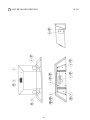
18. DESIGN RELATED PARTS ........................................................................... 90
19. PARTS LIST ..................................................................................................... 91 - 142
20. WIRE COLOR CODE TABLE ........................................................................ 143
21. WIRING DIAGRAM ........................................................................................ 144 - 146
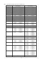
SPECIFICATIONS
Installation space
Height
Weight
Power, maximum current
For TAIWAN
Power, current
MONITOR
: 2,080 mm (W) X 1,860 mm (D)
(81.9 in. X 73.2 in.)
: 2,000 mm (78.7 in.)
If the pop panel is installed, the height becomes
2,510 mm (98.8 in)
: Approx. 502 kg. (1,106.7 lbs.)
: 690 W 7.8A (AC 110V 50 Hz AREA)
680 W 7.6A (AC 110V 60 Hz AREA)
700 W 7.2A (AC 120V 60 Hz AREA)
745 W 4.2A (AC 220V 50 Hz AREA)
700 W 4.0A (AC 220V 60 Hz AREA)
710 W 3.9A (AC 230V 50 Hz AREA)
680 W 3.7A (AC 230V 60 Hz AREA)
690 W 3.7A (AC 240V 50 Hz AREA)
680 W 3.6A (AC 240V 60 Hz AREA)
: 690 W 7.75A (MAX.)
375 W 4.50A (MIN.)
: 29 TYPE COLOR MONITOR
INTRODUCTION OF THE OWNERS MANUAL
This Owner's Manual is intended to provide detailed descriptions together with all
the necessary information covering the general operation of electronic assemblies,
electromechanicals, servicing control, spare parts, etc. as regards the product,
STRIKE FIGHTER DX TYPE.
This manual is intended for the owners, personnel and managers in charge of
operation of the product. Operate the product after carefully reading and sufficiently
understanding the instructions. If the product fails to function satisfactorily, nontechnical personnel should under no circumstances touch the internal system. Please
contact where the product was purchased from.
Use of this product is unlikely to cause physical injuries or damages to property. However,
where special attention is required this is indicated by a thick line, the word "IMPORTANT"
and its sign in this manual.
STOP
Indicates that mishandling the product by disregarding this display can cause the
product's intrinsic performance not to be obtained, resulting in malfunctioning.
IMPORTANT
SEGA ENTERPRISES, INC. (U.S.A.)/CUSTOMER SERVICE
45133 Industrial Drive, Fremont, California 94538, U.S.A.
Phone : (415) 701-6580
Fax : (415) 701-6594
DEFINITION OF LOCATION MAINTENANCE MAN AND SERVICEMAN
Non-technical personnel who do not have technical knowledge and expertise should
refrain from performing such work that this manual requires the location's
maintenance man or a serviceman to carry out, or work which is not explained in
this manual. Failing to comply with this instruction can cause a severe accident
such as electric shock.
Ensure that parts replacement, servicing & inspections, and troubleshooting are performed by the
location's maintenance man or the serviceman. It is instructed herein that particularly hazardous
work should be performed by the serviceman who has technical expertise and knowledge.
The location's maintenance man and serviceman are herein defined as follows:
"Location's Maintenance Man" :
Those who have experience in the maintenance of amusement equipment and vending machines,
etc., and also participate in the servicing and control of the equipment through such routine work
as equipment assembly and installation, servicing and inspections, replacement of units and
consumables, etc. within the Amusement Facilities and or locations under the management of the
Owner and Owner's Operators of the product.
Activities of Location's Maintenance Man :
Assembly & installation, servicing & inspections, and replacement of units & consumables as
regards amusement equipment, vending machines, etc.
Serviceman :
Those who participate in the designing, manufacturing, inspections and maintenance service of
the equipment at an amusement equipment manufacturer.
Those who have technical expertise equivalent to that of technical high school graduates as regards electricity, electronics and or mechanical engineering, and daily take part in the servicing &
control and repair of amusement equipment.
Serviceman's Activities :
Assembly & installation and repair & adjustments of electrical, electronic and mechanical parts of
amusement equipment and vending machines.
LISTED
UL
5K92
®
AMUSEMENT MACHINE
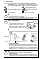
1. HANDLING PRECAUTIONS
When installing or inspecting the machine, be very careful of the following points and pay
attention to ensure that the player can enjoy the game safely.
Non-compliance with the following points or inappropriate handling running counter to the
cautionary matters herein stated can cause personal injury or damage to the machine.
Before performing work, be sure to turn power off. Performing the work
without turning power off can cause an electric shock or short circuit. In the
case work should be performed in the status of power on, this manual always
states to that effect.
To avoid electric shock or short circuit, do not plug in or unplug quickly.
To avoid electric shock, do not plug in or unplug with a wet hand.
Do not expose Power Cords and Earth Wires on the surface, (floor, passage,
etc.). If exposed, the Power Cords and Earth Wires are susceptible to damage.
Damaged cords and wires can cause electric shock or short circuit.
To avoid causing a fire or electric shock, do not put things on or damage
Power Cords.
When or after installing the product, do not unnecessarily pull the power cord.
If damaged, the power cord can cause a fire or electric shock.
In case the power cord is damaged, ask for replacement through where the
product was purchased from or the office herein stated. Using the cord as is
damaged can cause fire, electric shock or leakage.
Be sure to perform grounding appropriately. Inappropriate grounding can
cause an electric shock.
Be sure to use fuses meeting specified rating. Using fuses exceeding the
specified rating can cause a fire or electric shock.
Completely make connector connections for IC BD and others. Insufficient
insertion can cause an electric shock.
Specification changes, removal of equipment, conversion and/or addition, not
designated by SEGA are not permitted.
• Failure to observe this may cause a fire or an electric shock. Non-compliance
with this instruction can have a bad influence upon physical conditions of the
players or the lookers-on, or result in injury during play.
• SEGA shall not be held responsible for damage, compensation for damage to
a third party, caused by specification changes not designated by SEGA.
Be sure to perform periodic maintenance inspections herein stated.
STOP
IMPORTANT
For the IC board circuit inspections, only the logic tester is allowed. The use
of a multiple-purpose tester is not permitted, so be careful in this regard.
When cleaning the CRT surfaces, use a soft, dry cloth. Do not apply
chemicals such as thinner, benzine, etc.
The electronic parts on the IC Board could be damaged due to human body's
static electricity. Before performing IC Board related work, be sure to
discharge physically accumulated statics by touching grounded metallic
surfaces, etc.
1
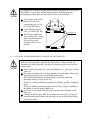
2. PRECAUTIONS CONCERNING INSTALLATION
LOCATION
This product is an indoor game machine. Do not install it outside. Even indoors,
avoid installing in places mentioned below so as not to cause a fire, electric shock,
injury and or malfunctioning.
Places subject to rain or water leakage, or places subject to high humidity in
the proximity of an indoor swimming pool and or shower, etc.
Places subject to direct sunlight, or places subject to high temperatures in the
proximity of heating units, etc.
Places filled with inflammable gas or vicinity of highly inflammable/volatile
chemicals or hazardous matter.
Dusty places.
Sloped surfaces.
Places subject to any type of violent impact.
Vicinity of anti-disaster facilities such as fire exits and fire extinguishers.
The operating (ambient) temperature range is from 5 Celsius to 40 Celsius.
Only in the case a projector is employed, the temperature range is from 5
Celsius to 30 Celsius.
LIMITATIONS OF USAGE REQUIREMENTS
Be sure to check the Electrical Specifications.
Ensure that this product is compatible with the location's power supply,
voltage and frequency requirements.
A plate describing Electrical Specifications is attached to the product.
Non-compliance with the Electrical Specifications can cause a fire and
electric shock.
This product requires the Breaker and Earth Mechanisms as part of the
location facilities. Using them in a manner not independent can cause a fire
and electric shock.
Ensure that the indoor wiring for the power supply is rated at 10A or higher
(AC single phase 100 ~ 120V area), and 5A or higher (AC 220 ~ 240V area).
Non-compliance with the Electrical Specifications can cause a fire and
electric shock.
Be sure to independently use the power supply equipped with the Earth
Leakage Breaker. Using a power supply without the Earth Leakage Breaker
can cause an outbreak of fire when earth leakage occurs.
Putting many loads on one electrical outlet can cause generation of heat and a
fire resulting from overload.
When using an extension cord, ensure that the cord is rated at 10A or higher
(AC 100 ~ 120V area) and 5A or higher (AC 220 ~ 240V area). Using a cord
rated lower than the specified rating can cause a fire and electric shock.
2
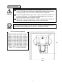
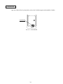
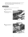
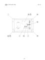
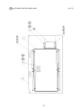
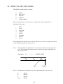
OPERATION AREA
For the operation of this machine, secure a minimum area of 2.8m (W) X
2.5m (D). In order to prevent injury resulting from the falling down accident
during game play, be sure to secure the minimum area for operation.
Be sure to provide sufficient space so as to allow this product's ventilation fan
to function efficiently. To avoid machine malfunctioning and a fire, do not
place any obstacles near the ventilation opening.
SEGA shall not be held responsible for damage, compensation for damage to
a third party, resulting from the failure to observe this instruction.
STOP
For transporting the machine into the location's building, the minimum necessary
dimensions of the opening (of doors, etc.) are 1.15m(W) and 2.1m(H).
IMPORTANT
Electric current consumption
MAX. 7.80 A (AC 110V 50 Hz)
MAX. 7.60 A (AC 110V 60 Hz)
MAX. 7.20 A (AC 120V 60 Hz)
MAX. 4.20 A (AC 220V 50 Hz)
MAX. 4.00 A (AC 220V 60 Hz)
MAX. 3.90 A (AC 230V 50 Hz)
MAX. 3.70 A (AC 230V 60 Hz)
MAX. 3.70 A (AC 240V 50 Hz)
MAX. 3.60 A (AC 240V 60 Hz)
MAX. 7.75 A (For TAIWAN)
200mm
2.5m
2.8m
FIG. 2
3
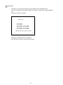
3. OPERATION
PRECAUTIONS TO BE HEEDED BEFORE STARTING THE OPERATION
To avoid injury and trouble, be sure to constantly give careful attention to the behavior and
manner of the visitors and players.
In order to avoid accidents, check the following before starting the operation:
To ensure maximum safety for the players and the customers, ensure that
where the product is operated has sufficient lighting to allow any warnings to
be read. Operation under insufficient lighting can cause bodily contact with
each other, hitting accident, and or trouble between customers.
Be sure to perform appropriate adjustment of the monitor (projector). For
operation of this machine, do not leave monitor's flickering or deviation as is.
Failure to observe this can have a bad influence upon the players' or the
customers' physical conditions.
It is suggested to ensure a space allowing the players who feel sick while
playing the game to take a rest.
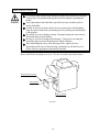
Check if all of the adjusters are in contact with the surface. If they are not, the
Cabinet can move and cause an accident.
1234567890123456789012345678901212345678901234567890123456789012123456789012345678901234567890
1234567890123456789012345678901212345678901234567890123456789012123456789012345678901234567890
1234567890123456789012345678901212345678901234567890123456789012123456789012345678901234567890
1234567890123456789012345678901212345678901234567890123456789012123456789012345678901234567890
1234567890123456789012345678901212345678901234567890123456789012123456789012345678901234567890
1234567890123456789012345678901212345678901234567890123456789012123456789012345678901234567890
1234567890123456789012345678901212345678901234567890123456789012123456789012345678901234567890
Ensure that all of the
Adjusters are in contact
with the floor.
4
Do not put any heavy item on this product. Placing any heavy item on the
product can cause a falling down accident or parts damage.
Do not climb on the product. Climbing on the product can cause falling down
accidents. To check the top portion of the product, use a step.
To avoid electric shock, check to see if door & cover parts are damaged or
omitted.
To avoid electric shock, short circuit and or parts damage, do not put the
following items on or in the periphery of the product.
Flower vases, flowerpots, cups, water tanks, cosmetics, and receptacles/
containers/vessels containing chemicals and water.
To avoid injury, be sure to provide sufficient space by considering the potentially
crowded situation at the installation location. Insufficient installation space can
cause making bodily contact with each other, hitting accidents, and or trouble
between customers.
PRECAUTIONS TO BE HEEDED DURING OPERATION (PAYING ATTENTION TO CUSTOMERS)
To avoid injury and trouble, be sure to constantly give careful attention to the behavior and
manner of the visitors and players.
To avoid injury and accidents, those who fall under the following categories
are not allowed to play the game.
• Those who need assistance such as the use of an apparatus when walking.
• Those who have high blood pressure or a heart problem.
• Those who have experienced muscle convulsion or loss of consciousness when
playing video game, etc.
• Those who have a trouble in the neck and or spinal cord.
• Intoxicated persons.
• Pregnant women or those who are in the likelihood of pregnancy.
• Persons susceptible to motion sickness.
• Persons whose act runs counter to the product's warning displays.
A player who has never been adversely affected by light stimulus might
experience dizziness or headache depending on his physical condition when
playing the game. Especially, small children can be subject to those
conditions. Caution guardians of small children to keep watch on their
children during play.
Instruct those who feel sick during play to have a medical examination.
To avoid injury resulting from falling down and electric shock due to spilled
drinks, instruct the player not to place heavy items or drinks on the product.
To avoid electric shock and short circuit, do not allow customers to put hands
and fingers or extraneous matter in the openings of the product or small
openings in or around the doors.
To avoid falling down and injury resulting from falling down, immediately
stop the customer's leaning against or climbing on the product, etc.
5
To avoid electric shock and short circuit, do not allow the customers to
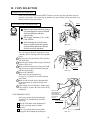
unplug the power plug without a justifiable reason.
This product is intended for 1 Player only. Playing the game by 2 or more
Players riding on the seat together can cause falling down and collision
accidents by striking head, hand, or elbow.
Caution lookers-on so as not to
touch the operating unit while
in play. Failure to observe this
may cause bodily contact with
the player and trouble between
the customers.
Caution the player so as not to
hold a child in her/his lap to
play. Failure to observe this
may cause the child to be
caught between the Control
Panel and the player and fall
down.
Immediately stop such violent acts as hitting and kicking the product. Such
violent acts can cause parts damage or falling down, resulting in injury due to
fragments and falling down.
Instruct the Player to adjust the seat before playing the game. Playing the
game in a forcible posture can cause a contingent accident.
6
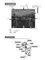
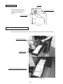
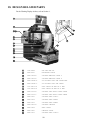
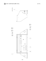
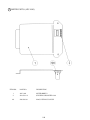
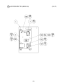
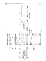
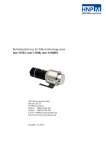
4. NAME OF PARTS
BILLBOARD
29 TYPE MONITER
CONTROL PANEL
FRONT CABINET
PEDAL UNIT
REAR CABINET
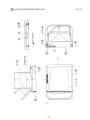
FIG. 4 a OVERVIEW
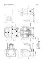
COIN CHUTE DOOR
AC UNIT
CASHBOX DOOR
FIG. 4 c REAR VIEW
FIG. 4 b FRONT VIEW
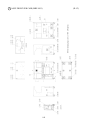
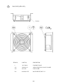
TABLE 4
Width
X
Length
X
Height
FRONT CABINET
2,080 mm X 1,040 mm
X 2,000 mm
REAR CABINET
1,040 mm X 1,075 mm
X 1,510 mm
When assembled
2,080 mm X 1,860 mm
X 2,000 mm
If the pop panel is installed,the height becomes 2,510mm.
7
Weight
400 kg
102 kg
502 kg
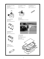
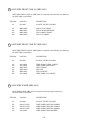
5. ACCESSORIES
When transporting the machine, make sure that the following parts are supplied.
TABLE 5 ACCESSORIES
DESCRIPTION
Part No. (Qty.)
Note
KEY MASTER
220-5576 (2)
For opening/closing
the doors
OWNERS MANUAL
420-6589-01 (1)
Figures
KEY
(2)
For the CASHBOX DOOR
If Part No. has no description, the Number has not been
registered or can not be registered. Such a part may not
be obtainable even if the customer desires to purchase it.
Therefore, ensure that the part is in safekeeping with you.
The Keys are inside the Coin
Chute Door at the time of
shipment from the factory.
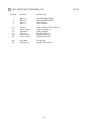
AC Cable (Power Cord)
600-6729
(1) TAIWAN
600-6724
600-6618 (1) AC 220 ~ 240V AREA
600-6619 (1) HONG KONG
600-6695 (1) USA
Used for installation, see 4 of Section 6.
CORD CLAMP
280-5009-01 (1)
Used for securing the
power cord.
see 4 of Section 6.
WIRE HARN EARTH W/LUG
M6
600-6664-02 (1)
For TAIWAN.
Used for installation,
see 4 of Section 6.
STATICIDE (300ML)
090-0074 (1)
Articles of consumption
(see below).
TAMPERPROOF†WRENCH
M4 540-0006-01 (1)
M5 540-0007-01 (1)
M8 540-0009-01 (1)
TOOL
Periodically once every two
months as standard, apply the
"STATICIDE" (an antistatic spray
agent) to the SEATs and wipe with
a dry cloth.
8
VOL CONT B-5K OHM
220-5373
(1)
220-5484
Spare, see Section 10, 11.
SW MICRO TYPE
509-5974 (1)
Spare, refer to Section 10.
VOL CONT B-5K OHM
220-5737 (1)
Spare, see Section 10.
Heat-Shrinkable Tubing
310-5029-F20 (6)
Spare, see Section 10, 11.
POP PANEL
429-0688 (1)
Used for installation, see Section 6.
SW MICRO TYPE
509-5975 (1)
Spare, refer to Section 10.
CARTON BOX
601-10577 (1)
Used for transporting the
Game Board.
Refer to Next Page.
FUSE 6.3A
514-5086-6300 (1)
Spare, see Section 16.
9
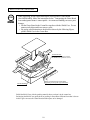
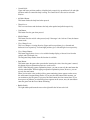
HOW TO USE THE CARTON BOX
When requesting for the replacement/repair of this product's Game Board
(NAOMI BOARD), follow the instructions below. Transporting the Game Board
in an undesignated status is unacceptable. An erroneous handling can cause parts
damage.
• Put the Game Board in the Carton Box together with the Shield Case. Do not
unnecessarily disassemble nor remove parts.
• By paying careful attention to the direction shown by the following Figure,
put the Shield Case in the Carton Box.
STOP
IMPORTANT
I
GR
P
FILTER BD side.
Ensure that the direction in which
the Shield Case is packed is correct.
I
GR
P
Remove the Brackets (the shape differs
depending on the specific type of machine).
FILTER BOARD
Enfold the Shield Case with the packing material shown, and put it in the carton box.
Positioning the Shield Case upside down or packing in the manner different from what is shown
in this Figure can cause the Game Board and other parts to be damaged.
10
6. ASSEMBLING AND INSTALLATION
Perform assembly work by following the procedure herein stated. Failing to
comply with the instructions can cause electric shock hazard.
Perform assembling as per this manual. Since this is a complex machine,
erroneous assembling can cause an electric shock, machine damage and or not
functioning as per specified performance.
When assembling, be sure to use plural persons. Depending on the assembly
work, there are some cases in which working by one person alone can cause
personal injury or parts damage.
Ensure that connectors are accurately connected. Incomplete connections can
cause electric shock hazard.
Be careful so as not to damage wirings. Damaged wiring can cause electric
shock and short circuit hazards.
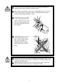
In the case the cabinet is separated into the front and rear portions, do not
push the upper rear part of the front cabinet. Failure to observe this causes the
front cabinet to fall down towards the monitor side and result in accidents and
injury to persons. When moving the front cabinet in the above case, be sure to
push it from side directions and move it by 2 or more persons for safety.
This work should be performed by the Location's Maintenance Man or
Serviceman. Performing work by non-technical personnel can cause a severe
accident such as electric shock. Failing to comply with this instruction can
cause a severe accident such as electric shock to the player during operation.
Provide sufficient space so that assembling can be performed. Performing
work in places with narrow space or low ceiling may cause an accident and
assembly work to be difficult.
To perform work safely and avoid serious accident such as the cabinet's
falling down, do not perform work in places where step-like grade
differences, a ditch, or slope exist.
When handling plastic parts, use care. Do not give a shock or apply excessive
load to the fluorescent lamps and plastic parts. Failure to observe this can
cause parts damage, resulting in injury due to fragments, cracks and broken
pieces.
To perform work safely and securely, be sure to prepare a step which is in a
secure and stable condition. Performing work without using the step can
cause violent falling down accidents.
11
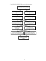
When carrying out the assembling and installation, follow the following 5-item sequence.
1
2
3
4
5
ASSEMBLING THE CABINET
SECURING IN PLACE (ADJUSTER ADJUSTMENT)
POWER SUPPLY, AND EARTH CONNECTION
TURNING POWER ON
ASSEMBLING CHECK
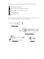
The master key (accessories) in addition to the tools such as a Phillips type screwdriver, wrench,
socket wrench and Ratchet Handle are required for the assembly work.
Phillips type screwdriver
24mm
WRENCH (for M16 hexagon bolt)
SOCKET WRENCH,(for M8 hexagon bolt)
RATCHET HANDLE
12
KEY MASTER
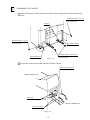
1
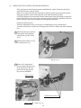
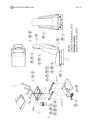
ASSEMBLING THE CABINET
1 Install Joint Bracket L & R to both sides of Front Cabinet as applicable, and 2 Joint Pipes to the
inside.
HEXAGON BOLT (2) black
M8 X 30, w/spring washer,
flat washer used.
Joint Pipe
HEXAGON BOLT (3) black
M8 X 20, w/spring washer,
flat washer used.
JOINT BRACKET R
JOINT BRACKET L
FIG. 6. 1 a
HEXAGON BOLT (4 each) black
M8 X 20, w/spring washer,
flat washer used.
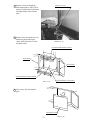
2 Connect the wiring from the Front Cabinet to the Rear Cabinet.
Connect the Connectors.(2)
blue 4P,white 3P
REAR CABINET side
SCREW (2)
M4 X 8, flat & spring washers used.
FRONT CABINET side
Connect the Earth.(2)
FIG. 6. 1 b
13
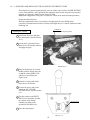
3 Insert the Front Cabinet's square pipes into the Rear Cabinet's square holes to fit both cabinets
tight and secure with a total of 4 Hexagon Bolts.
HEXAGON BOLT (2) black
M8 X 20, w/spring washer,
flat washer used.
HEXAGON BOLT (2) black
M8 X 20, w/spring washer,
flat washer used.
FIG. 6. 1 c
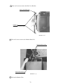
4 Apply the POP PANEL to the
top of BILLBOARD.
POP PANEL
When performing work,
be sure to use a step.
FIG. 6. 1 d
14
2
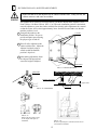
SECURING IN PLACE (ADJUSTER ADJUSTMENT)
Make sure that all of the adjusters are in contact with the floor. If they are not, the
cabinet can move and cause an accident.
This product has 10 casters (6 for Front Cabinet, 4 for Rear Cabinet) and 8 Adjusters (4 for
Front Cabinet, 4 for Rear Cabinet). (FIG. 6. 2a) When the installation position is determined,
cause the adjusters to come into contact with the floor directly, make adjustments in a manner
so that the casters will be raised approximately 5mm. from the floor and make sure that the
machine position is level.
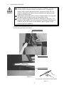
1 Transport the product to the
CASTER
installation position. Be sure to
provide adequate space allowing
the player to get on and off.
2 Have all of the Adjusters make
contact with the floor. Adjust the
Adjuster's height by using a
wrench so that the machine
position is kept level.
3 After making adjustment, fasten
the Adjuster Nut upward and
secure the height of Adjuster.
ADJUSTER
FIG. 6. 2 a BOTTOM VIEW
ADJUSTER
CASTER
FASTEN UPWARD.
Approx.5mm
ADJUSTER
FIG. 6. 2 b ADJUSTER
FIG. 6. 2 c
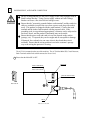
Refer to this Fig. (Scale:1/100)
for the layout of the place of
installation.
FIG. 6. 2 d
Be sure to provide space as shown between the Air
Vent and the wall surface.
15
3
POWER SUPPLY, AND EARTH CONNECTION
Be sure to independently use the power supply socket outlet equipped with an
Earth Leakage Breaker. Using a power supply without an Earth Leakage
Breaker can cause a fire when electric leakage occurs.
Ensure that the "accurately grounded indoor earth terminal" and the earth wire
cable are available (except in the case where a power cord plug with earth is
used). This product is equipped with the earth terminal. Connect the earth
terminal and the indoor earth terminal with the prepared cable. If the
grounding work is not performed appropriately, customers can be subjected to
an electric shock, and the product's functioning may not be stable.
Ensure that the power cord and earth wire are not exposed on the surface
(passage, etc.). If exposed, they can be caught and are susceptible to damage.
If damaged, the cord and wire can cause electric shock and short circuit
accidents. Ensure that the wiring position is not in the customer's passage
way or the wiring has protective covering.
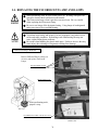
The AC Unit is mounted on the rear of the machine. The AC Unit has Main SW, Circuit Protector,
Earth Terminal and the Inlet which connects the Power Cord.
1 Ensure that the Main SW is OFF.
MAIN SW
EARTH TERMINAL
Connect with the
indoor earth terminal.
CIRCUIT PROTECTOR
Main SW off
INLET
FIG. 6. 3 a AC unit
16
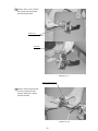
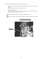
2 Connect one end of the earth wire to the
Connect the Earth Wire
to the Earth Terminal.
AC Unit earth terminal, and the other end
to the indoor earth terminal. The AC
Unit earth terminal has a Bolt and Nut
combination. Take off the Nut, pass the
end of earth wire through the Bolt, and
fasten the Nut.
Note that the Earth Wire is incorporated
in the Power Cord for the Areas of AC
120V (USA) and AC 220 ~ 240V, and
therefore, this procedure is not necessary.
FIG. 6. 3 b Earth Wire Connection
3 Firmly insert the power plug into
the socket outlet.
Insert the opposite side of Power
Cord plug to the AC Unit's
connector ("INLET").
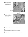
4 Perform wiring for the Power Cord
and Earth Wire. Install protective
covering for the Power Cord and
Earth Wire.
Wiring Cover
FIG. 6. 3 c Connecting Power Cord and Earth Wire
In case the Power Plug is apt to come out of place, secure the
Power Cord to the periphery of the AC Unit with the Cord
Clamp (an accessory).
HOW TO USE THE CORD CLAMP
17
4
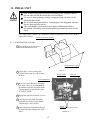
TURNING POWER ON
Turn the AC unit's main switch on to connect the power. Then the 3 monitors are turned on;
about 15 seconds after that the fluorescent lamps in the billboard and the console panel are
turned on. A few more seconds later the screen displays a system power-on message and then an
advertising (ply for hire) picture. Furthermore some advertising sounds are heard from the
speakers on the right and left of the control panel. Also the bass shaker (vibrator) and woofer
under the seat output the sounds. The sounds are not heard if you have set this function to off
(disabled).
The playing data, such as credit number, ranking, and latest-obtained scores, are stored in the
memory even after disconnecting the power. The data of the fractional coins (the inserted coins
under one credit) and the data in the bonus adder count are not stored. Assume that you have
disconnected the power with remaining the credit numbers enough to replay. When you
reconnect the power, the screen immediately displays an advertising picture; now you can start
to play the game by pressing the start button.
Fluorescent lamp
(in the billboard)on
Image output on the monitor.
Emits sounds.
Bass shaker and woofer
(under the seat)
Fluorescent lamp
(in the console panel)on
FIG. 6. 4
18
5
ASSEMBLING CHECK
In the TEST MODE, ascertain that the assembly has been made correctly and IC BD. is
satisfactory (refer to Section 9).
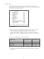
In the test mode, perform the following test:
(1) MEMORY TEST
Selecting the RAM TEST and ROM TEST on the SYSTEM TEST mode menu screen causes
the on-board memory to be tested automatically. The game board is satisfactory if the display
beside each IC No. shows GOOD.
ROM BOARD TEST
[XXXXXXXXXXXXXXXXXXX]
RAM TEST
IC29
IC35
IC16
IC20
IC09
IC11
GOOD
GOOD
GOOD
GOOD
GOOD
GOOD
IC18
IC22
IC10
IC12
NO. TYPE RESULT BYTE WORD
IC22 32M ---- XXXX XXXX
IC1 64M GOOD XXXX XXXX
IC2 64M GOOD XXXX XXXX
IC3 64M GOOD XXXX XXXX
IC4 64M GOOD XXXX XXXX
IC5 64M GOOD XXXX XXXX
IC6 64M GOOD XXXX XXXX
IC7 64M GOOD XXXX XXXX
IC8 64M GOOD XXXX XXXX
IC9 64M GOOD XXXX XXXX
IC10 64M GOOD XXXX XXXX
IC11 64M GOOD XXXX XXXX
•••• ••• •••• •••• ••••
IC20 64M GOOD XXXX XXXX
GOOD
GOOD
GOOD
GOOD
PRESS TEST BUTTON TO EXIT
PRESS TEST BUTTON TO EXIT
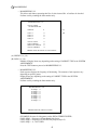
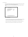
(2) SOUND TEST
In the SYSTEM TEST mode, selecting
SOUND TEST causes the screen (on which
sound related BD and wiring connections
are tested) to be displayed.
Check if the sound is satisfactorily emitted
from each speaker and the sound volume is
appropriate.
SOUND TEST
RIGHT SPEAKER
LEFT SPEAKER
-> EXIT
OFF
OFF
SELECT WITH SERVICE BUTTON
AND PRESS TEST BUTTON
19
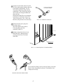
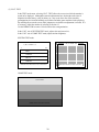
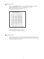
(3) C.R.T. TEST
In the TEST mode menu, selecting C.R.T. TEST allows the screen (on which the monitor is
tested) to be displayed. Although the monitor adjustments have been made at the time of
shipment from the factory, color deviation, etc., may occur due to the effect caused by
geomagnetism, the location building's steel frames and other game machines in the periphery.
By watching the test mode screen, make judgment as to whether an adjustment is needed. If it
is necessary, adjust the monitor by referring to Section 13.
Use the DEMAG SW to remove color deviation due to magnetization.
In the C.R.T. test of SYSTEM TEST mode, adjust color and screen size.
In the C.R.T. test of GAME TEST mode, adjust monitor brightness.
SYSTEM TEST mode
C.R.T. TEST 1/2
1
32
RED
GREEN
BLUE
WHITE
PRESS TEST BUTTON TO CONTINUE
GAME TEST mode
C.R.T. TEST
PRESS TEST BUTTON TO EXIT
20
12345678901234567890123
12345678901234567890123
C.R.T. TEST 2/2
12345678901234567890123
12345678901234567890123
12345678901234567890123
12345678901234567890123
12345678901234567890123
12345678901234567890123
12345678901234567890123
12345678901234567890123
12345678901234567890123
12345678901234567890123
12345678901234567890123
12345678901234567890123
12345678901234567890123
12345678901234567890123
12345678901234567890123
12345678901234567890123
12345678901234567890123
PRESS TEST BUTTON TO EXIT
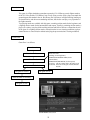
(4) INPUT TEST
INPUT TEST
GUN TRIGGER
MISSILE BUTTON
AIR BRAKE
VIEW CHANGE
VIEW UP
VIEW BACK
VIEW LEFT
VIEW RIGHT
START BUTTON
SERVICE
TEST
CONTROL STICK(AILERON)
CONTROL STICK(ELEVATOR)
RUDDER PEDAL
THRUST LEVER
Selecting the INPUT TEST on the GAME
TEST mode menu screen causes the screen
(on which each switch and V.R. are tested)
to be displayed. Press each switch. If the
display beside each switch indicates "ON,"
the switch and wiring connections are
satisfactory.
OFF
OFF
OFF
OFF
OFF
OFF
OFF
OFF
OFF
OFF
OFF
ABH
ABH
ABH
ABH
PRESS TEST AND SERVICE BUTTON TO EXIT
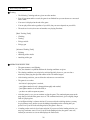
(5) OUTPUT TEST
Select OUTPUT TEST from the menu in the
GAME TEST mode to cause the screen
(on which each lamp is tested) to appear.
Ensure that each lamp lights up
satisfactorily.
OUTPUT TEST
START BUTTON LAMP
VIEW CHANGE LAMP
WARNING LAMP
BASS SHAKER
-> EXIT
OFF
OFF
OFF
OFF
SELECT WITH SERVICE BUTTON
AND PRESS TEST BUTTON
Perform the above inspections also at the time of monthly inspection.
21
7. PRECAUTIONS TO BE HEEDED WHEN MOVING THE MACHINE
When moving the machine, be sure to unplug the power plug. Moving the
machine with the plug as is inserted can damage the power cord and cause fire
and electric shock hazards.
When moving the machine on the floor, retract the Adjusters and ensure that
Casters make contact with the floor. During transportation, pay careful
attention so that Casters do not tread power cords and earth wires. Damaging
the power cords can cause electric shock and short circuit hazards.
When lifting the cabinet, be sure to hold the grip portions or bottom part.
Lifting the cabinet by holding other portions can damage parts and installation
portions due to the empty weight of the cabinet, and cause personal injury.
In the case the cabinet is separated into the front and rear portions, do not
push the upper rear part of the front cabinet. Failure to observe this causes the
front cabinet to fall down towards the monitor side and result in accidents and
injury to persons. When moving the front cabinet in the above case, be sure to
push it from side directions and move it by 2 or more persons for safety.
Do not push the plastic parts and the glass parts. Doing so may damage such parts
and as a result you may be injured with the broken pieces.
STOP
IMPORTANT
When transporting the product in places with steps, disassemble into each unit
before transporting. Inclining the product in an as is assembled condition or
placing the cabinet in places with steps can damage the unit's joining portions.
In the case the cabinet is
separated into the front and
rear portions, do not push the
upper rear part of the front
cabinet.
FIG. 7 a
22
GRIP
1234567890123456789012345678901212345678901234567890123456789
1234567890123456789012345678901212345678901234567890123456789
1234567890123456789012345678901212345678901234567890123456789
1234567890123456789012345678901212345678901234567890123456789
Have casters make contact with the floor.
FIG. 7 b
When transporting the product in places
with steps or step-like differences in
grade, disassemble into each unit before
transporting.
FIG. 7 c
23
8. CONTENTS OF GAME
The following explanations apply to the case the product is functioning satisfactorily. Should
there be any moves different from the following contents, some sort of faults may have
occurred. Immediately look into the cause of the fault and eliminate the cause thereof to ensure
satisfactory operation.
Always when the power is connected, the fluorescent lamps in the billboard and the console
panel are on. When in an advertising state, the screen displays the demonstration pictures and
ranking data. Sounds are heard from the speakers on the right and left of the control panel as
well as from the bass shaker (vibrator) and the woofer under the seat. The advertising sounds
are not heard if you have set this function to off (disabled).
The start button and the view change button are integrated with a lamp. The start button (lamp)
flashes when the coins are inserted enough to play the game. Both the right and left warning
lamps flash, as required, to attract the player's attention.
WARNING LAMP
Fluorescent lamp
(in the billboard)on
Image output on the monitor.
START BUTTON
Coin Inlet
VIEW CHANGE BUTTON
CONTROL PANEL
Emits sounds.
Bass shaker and woofer
(under the seat)
Fluorescent lamp
(in the console panel)on
FIG. 8
24
Introduction
This game is a flight-simulation game that assumes the F/A-18 Hornet, a main fighter-attacker
of the U.S. Navy and the U.S. Marine Corps. Freely flying over the field, a player can attack the
ground targets and combat in the air. He/she may also experience in-flight refueling, landing on
an aircraft carrier, and other non-combating missions; thus he/she can enjoy every operation of
the fighter-attacker
Two playing modes are available with this game: a training mission mode for the beginners and
a fighting mission mode for the intermediates and experts. Usually in a training mission mode, a
player (as a trainee) can play all the training missions and his/her skills are evaluated at the end
of the game. In a fighting mission mode, each mission has its own clearing conditions; a player
cannot advance to a next mission without satisfying the present mission's clearing conditions.
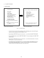
Game Flow
Game flow is as follows:
Insert the coins.
Press the start button.
Select a mode.
Play the selected mission.
The game is cleared.
Select one from:
Training (for the beginners)
OPERATION DESERT FIRE (for the
intermediates)
OPERATION RED ROCK (for the experts)
To select: Tilt the control stick to the right or left.
To decide: Press one of the gun, missile, and start
buttons.
The game is over.
Enter the name if necessary.
The game is over.
GAME MODE select screen
25
How to Play Each Mission
Training
• The following 7 training tasks are given one after another.
• Even if you cannot achieve a task, the game is not finished but you can advance to a next task
after a while.
• Your score is displayed at the end of the game.
• You can play all the tasks regardless of you skills, but your score depends on your skills.
• The tasks are in series; there are no branches on a playing flowchart.
[Basic Training Tasks]
• Climbing
• Turning
• Firing a missile
• Firing a gun
[Advanced Training Tasks]
• Fighting
• Attacking with a missile
• Attacking with a gun
OPERATION DESERT FIRE
• The game assumes a real fighting.
• First, the situation is explained and then the clearing conditions are given.
• The clearing conditions vary mission by mission. Basically, however, you can clear a
mission by destroying the specified number of the TG-marked targets.
• After clearing a mission, you are allowed to advance to a next mission.
• The game is over when:
- the limit of a playing time is reached,
- your fighter-attacker's body is damaged thoroughly and crashed,
- your fighter-attacker is out of the field, or
- you have no usable weapons anymore.
• After the game is over, you can continue to play the game. The continued game starts at the
stage that you left when the game was over. The continued mission is given a slightly longer
limit of a playing time.
• An in-flight refueling is a bonus mission. If you succeed in the refueling mission, you may
be given bonus scores and/or recover the damages depending on the refueling time you
spent. Even if you fail in the refueling mission, the game is not over.
• A landing on the carrier is also a bonus mission. If you succeed in the landing mission, you
may be given bonus scores. Even if you fail in the landing mission, the game is not over;
instead you can move to a screen that displays the final results.
26
• The OPERATION DESERT FIRE covers the following missions:
Attacking the ground targets
F channel recovering operation
Fighting in the air
Intercepting the bombers
Fighting in the air
Intercepting the bombers
In-flight refueling
(bonus)
In-flight refueling
(bonus)
Attacking the ground targets
Attacking the advance base
Attacking the ground targets
Attacking the airport
Fighting in the air
Scrambling
Fighting in the air
Requesting for backup
Attacking the ground targets
Operation 'Gain control of oil plant'
Attacking the ground targets
Operation 'Attack strategic point'
Landing on the carrier
(final)
27
OPERATION RED ROCK
•Basically, the above descriptions in the OPERATION DESERT FIRE are applicable to this OPERATION RED ROCK.
• The OPERATION DESERT FIRE covers the following missions:
Fighting in the air
Intercepting the attackers
Attacking the ground targets
Attacking the submarine base
Attacking the ground targets
Attacking the rocket launch complex
Fighting in the air
Escorting the air carrier
Fighting in the air
Escorting the bombers
In-flight refueling
(bonus)
In-flight refueling
(bonus)
Attacking the ground targets
Attacking the bridges
Attacking the ground targets
Attacking the radar facilities
Fighting in the air
Combating air patrol
Fighting in the air
Requesting for backup
Attacking the ground targets
Attacking the military targets
Attacking the ground targets
Attacking the secret military base
Landing on the carrier
(final)
28
Game Screen Layout
Score
Remaining missiles
Remaining guns
Number of TG to be
destroyed before clearing the
mission
Limit of playing time
Altitude
Speed
Body damage percentage
Radar
Orange :
TG-marked enemies
Violet :
Other enemies
Light blue : Friends
Yellow :
Missile
Operation Controls
The following operating and inputting controls are equipped.
Missile Button
View Change Lever
Gun Button
Thrust Lever
View Change Button
Air Brake Button
Control Stick
Start Button
Rudder Pedals
29
• Control Stick:
Upper and lower positions enable to climb the body respectively up and down. Left and right
positions enable to control the body's rolling. The control stick is also used to select the
mission.
• Air Brake Button:
This button brakes the body hard when pressed.
• Thrust Lever:
This lever accelerates and decelerates the body when pushed and pulled respectively.
• Gun Button:
This button fires the gun when pressed.
• Missile Button:
This button fires the missile when pressed, only if the target is in a lock-on. If not, the button
cannot work.
• View Change Lever:
This lever changes a viewing direction. Upper and lower positions give a forward and
backward view respectively. Left and right positions give a left and right view respectively.
• View Change Button:
This button toggles three views: a view with the headup display, a forward view from the
cockpit, and a backward view.
The integrated lamp flashes when this function is available.
• Start Button:
This button starts the game when pressed after inserting the coins. Once the game is started,
this button skips an explanation picture etc. on the screen.
NOTE: When skipping a game-explanation picture, you can use not only the start button but
also the other buttons. When skipping an operation-explanation picture, however, you can
use only the start button.
When you insert the coins (credits) while a game-continuing picture appears on the screen,
the start button's integrated lamp flashes. If you press the start button at this moment, you
can continue to play the game. If you press the other buttons, the time counts faster. If you
do not press any buttons, an advertising picture appears on the screen; now, the start button
starts the game from the first without continuing.
• Rudder Pedals:
The right rudder pedal turns the nose to the right while the left one to the left.
30
Scores
• For the training:
The shorter the time (seconds) to complete a training task, the higher the score.
• For the OPERATION DESERT FIRE and the OPERATION RED ROCK:
Target scores are obtained when you destroy the targets while bonus scores when you clear the
mission.
• The shorter the time to destroy a target, the higher the score. The more the destroyed targets,
the higher the score.
• If you continue to play a mission, the target scores are cleared to 0 (zero).
• For the OPERATION DESERT FIRE and the OPERATION RED ROCK:
You are raked at the end of the game, depending on the number of continuation, as follows:
Ranks
Colonel
Lieutenant Colonel
Major
Captain
First Lieutenant
Second Lieutenant
Number of Continuation
0
1
2
3
4
5 or more
• Ranking (score)
31
9. EXPLANATION OF TEST AND DATA DISPLAY
By operating the switch unit, periodically perform the tests and data check. When installing the
machine initially or collecting cash, or when the machine does not function correctly, perform
checking in accordance with the explanations given in this section.
The following shows tests and modes that should be utilized as applicable.
NAOMI GAME BOARD is used for the product. The system of this game board allows
another game to be played by replacing the ROM Board Case mounted on the NAOMI CASE.
As such, the Test Mode of this system consists of the System Test Mode for the system to
execute SELF-TEST, COIN ASSIGNMENTS, etc. used in common for the machines
employing the NAOMI BOARD, and the Game Test Mode for the specific product to execute
Input/Output test for the operation equipment, difficulty setting, etc.
TABLE 9 EXPLANATION OF TEST MODE
ITEMS
DESCRIPTION
REFERENCE
SECTIONS
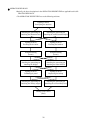
INSTALLATION
OF MACHINE
When the machine is installed, perform the following:
1. Check to ensure each is the standard setting at shipment.
2. Check each Input equipment in the INPUT TEST mode.
3. Check each Output equipment in the OUTPUT TEST mode.
4. Test on-IC-Board IC's in the SELF-TEST mode.
MEMORY
This test is automatically executed by selecting RAM TEST, or 9-2/1, 9-2/10
ROM BOARD TEST in the Menu mode.
PERIODIC
SERVICING
Periodically perform the following:
1. MEMORY TEST
2. Ascertain each setting.
3. To test each Input equipment in the INPUT TEST mode.
4. To test each Output equipment in the OUTPUT TEST mode.
CONTROL
SYSTEM
9-2/2, 9-3B
1. To check each Input equipment in the INPUT TEST mode.
9-3B,F
2. Adjust or replace each Input equipment.
3. If the problem still remains unsolved, check each equipment's 10, 11
mechanism movements.
MONITOR
In the Monitor Adjustment mode, check to see if Monitor (Projec- 9-2/4, 9-3D
13
tor) adjustments are appropriate.
IC BOARD
MEMORY TEST
DATA CHECK
Check such data as game play time and histogram to adjust the 9-2/7
9-3G
difficulty level, etc.
9-2/5, 9-3E
9-3B
9-2/3, 9-3C
9-2/1, 9-2/10
9-2/1, 9-2/10
9-2/5, 9-3E
9-3B
9-2/3, 9-3C
9-2/1, 9-2/10
32
9 - 1 SWITCH UNIT AND COIN METER
Never touch places other than those specified. Touching places not specified can
cause electric shock and short circuit accidents.
Adjust to the optimum sound volume by considering the environmental
requirements of the installation location.
If the COIN METER and the game board are electrically disconnected, game
play is not possible.
If you increase the woofer and bass shaker volumes, some parts of their
enclosures may resonate due to their own acoustic characteristics, and
eventually abnormal sounds are heard. To stop such resonant sounds, reduce
the volumes.
STOP
IMPORTANT
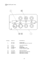
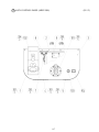
SWITCH UNIT
Open the coin chute door, and the switch unit shown will appear. The function of each SW is as
follows:
DEMAGNETIZER SWITCH
SERVICE BUTTON
SPEAKER VOLUME
SPEAKER VOLUME
TEST BUTTON
FIG. 9. 1 a SWITCH UNIT
SPEAKER VOLUME:
Sound volume can be adjusted for the 2 Speakers.
SPEAKER
SPEAKER VOLUME:
WOOFER
TEST BUTTON:
Adjusts the sound volume of WOOFER and the vibration of
BASS SHAKER.
TEST
For the handling of the TEST BUTTON, refer to the following
pages.
SERVICE BUTTON:
Gives credits without registering on the coin meter.
SERVICE
DEMAGNETIZER SWITCH: Eliminates the on-screen color unevenness due to magnetization
of CRT. First use this SW before performing the monitor's color
DEMAG.
adjustment. Each monitor has this switch.
33
COIN METER
Open the Cashbox Door by using the key to have the Coin Meter appear underneath the Cashbox.
COIN METER
FIG. 9. 1 b COIN METER
34
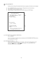
9 - 2 SYSTEM TEST MODE
STOP
IMPORTANT
The contents of setting changes in SYSTEM ASSIGNMENTS, COIN
ASSIGNMENTS, and GAME TEST MODE are stored when the test mode is
EXITed. If the power is turned off before EXITing, the contents of setting
changes are ineffective. Be very careful of this point.
This test mode mainly allows the IC Board to be checked for accurate functioning, monitor
color to be adjusted as well as COIN ASSIGNMENTS and GAME ASSIGNMENTS to be
adjusted.
TEST ITEM SELECT
1)
After turning power on, press the TEST button to have the following test item menu displayed.
Although the menu is displayed on all of the 3 monitors (front, left and right), perform work by
watching the front monitor only.
SYSTEM MENU
XXXX VERSION
RAM TEST
JVS TEST
SOUND TEST
C.R.T. TEST
SYSTEM ASSIGNMENTS
COIN ASSIGNMENTS
BOOKKEEPING
BACKUP DATA CLEAR
CLOCK SETTING
ROM BOARD TEST
GAME TEST MODE
[XXXXXXXXXXXXXXXXXXX]
-> EXIT
SELECT WITH SERVICE BUTTON
AND PRESS TEST BUTTON
2)
Press the SERVICE button to move the arrow. Bring the arrow to the desired item and press the
TEST button.
3)
Upon finishing the test, bring the arrow to EXIT and press the TEST button to return to the
Game mode.
35
1 RAM TEST
This allows for checking the functioning of the RAM on the NAOMI Main BD.
"GOOD" is displayed for satisfactory RAMs, and "BAD" is indicated for irregular RAMs, if
any.
In this test, check the 3 monitors.
RAM TEST
IC29
IC35
IC16
IC20
IC09
IC11
GOOD
GOOD
GOOD
GOOD
GOOD
GOOD
IC18
IC22
IC10
IC12
GOOD
GOOD
GOOD
GOOD
PRESS TEST BUTTON TO EXIT
During test, "TESTING NOW" is displayed.
Press the TEST button to return to the menu mode.
36
2 JVS TEST
In this test, Specifications of the I/O Board connected to NAOMI can be checked, and INPUT
TEST can be performed. First, I/O Board Specifications are displayed.
JVS TEST
INPUT TEST
(A)
NEXT NODE
(B)
-> EXIT
(C)
NODE
1/1
NAME
SEGA ENTERPRISES,LTD.
I/O BD JVS
837-13551
Ver 1.00
CMD VER
1.1
JVS VER
2.0
COM VER
1.0
SWITCH
2PLAYER(S) 11BITS
COIN
2SLOT
ANALOG
8CH
ROTARY
0CH
KEYCODE
0
SCREEN
X:0 Y:0 CH:0
CARD
OSLOT
HOPPER OUT 0CH
DRIVER OUT 8SLOT
ANALOG OUT 0CH
CHARACTER CHARA:0 LINE:0
BACKUP
0
SELECT WITH SERVICE BUTTON
AND PRESS TEST BUTTON
Select with the SERVICE button and press the TEST button.
(1) INPUT TEST : Proceeds to the INPUT TEST of I/O BOARD being displayed.
(2) NEXT NODE : In the case where more than 2 I/O Boards are connected, proceeds to
the next I/O Board.
(3) EXIT
: Returns to the menu mode.
INPUT TEST SCREEN
JVS TEST
INPUT TEST
NEXT NODE
-> EXIT
NODE 1/1
SWITCH
SYSTEM
PLAYER1
PLAYER2
When INPUT is performed for the switches
of Control Panel, etc., the value changes to
1 from 0.
00000000
00000000
00000000
00000000
00000000
If the Coin SW is inputted, the value
momentarily changes to 1 from 0.
COIN
0000 0000
ANALOG
0000 0000 0000 0000
0000 0000 0000 0000
Analogue values are displayed between
0000 and FF00.
SELECT WITH SERVICE BUTTON
AND PRESS TEST BUTTON
37
3 SOUND TEST
Sound Output test can be performed. Beep sounds can be emitted from each of left/right Speakers.
SOUND TEST
Emitted from the right-hand side Speaker.
Emitted from the left-hand side Speaker.
Returns to the menu mode.
RIGHT SPEAKER OFF
LEFT SPEAKER OFF
-> EXIT
SELECT WITH SERVICE BUTTON
AND PRESS TEST BUTTON
4 C.R.T. TEST
A) RGB COLOR ADJUSTMENT SCREEN
In this page, monitor color can be checked.
C.R.T. TEST 1/2
1
32
RED
GREEN
BLUE
WHITE
Each of red, green, and blue is the darkest at the
leftmost end, and becomes brighter towards the
right-hand end in 31 gradations. Monitor
brightness is satisfactory if the white color bar
is black at the left end and if it is white at the
right end.
Press the TEST button to proceed to the next
page.
PRESS TEST BUTTON TO CONTINUE
B) MONITOR SIZE ADJUSTMENT SCREEN
In this page, monitor size can be checked.
12345678901234567890123
12345678901234567890123
C.R.T. TEST 2/2
12345678901234567890123
12345678901234567890123
12345678901234567890123
12345678901234567890123
12345678901234567890123
12345678901234567890123
12345678901234567890123
12345678901234567890123
12345678901234567890123
12345678901234567890123
12345678901234567890123
12345678901234567890123
12345678901234567890123
12345678901234567890123
12345678901234567890123
12345678901234567890123
12345678901234567890123
PRESS TEST BUTTON TO EXIT
38
Adjust so that the checkered patterns do not go
beyond the screen.
Press the TEST button to return to the menu
mode.
5 SYSTEM ASSIGNMENTS
STOP
IMPORTANT
If the settings of CABINET TYPE and MONITOR TYPE are not suitable for the
connected game, Error Message is displayed after turning power on and upon
finishing the TEST mode, and in this case, game is not playable.
The setting of cabinet and board can be changed. Game related assignments such as game
difficulty, etc. are performed in áJGAME TEST MODE.
1)
2)
3)
Press the SERVICE button to move the arrow. Bring the arrow to the desired item.
Press the TEST button to change the setting.
Upon finishing the setting, move the arrow to EXIT and press the TEST button.
SYSTEM ASSIGNMENTS
CABINET TYPE 1PLAYER(S)
ADVETISE SOUND ON
MONITOR TYPE HORIZONTAL
SERVICE TYPE COMMON
-> EXIT
(A)
(B)
(C)
(D)
SELECT WITH SERVICE BUTTON
AND PRESS TEST BUTTON
(A) CABINET TYPE (1PLAYER(S), 2PLAYER(S), 3PLAYER(S), 4PLAYER(S))
Fix setting to 1 PLAYER(S).
(B) ADVERTISE SOUND (ON, OFF)
Sets whether ADVERTISE sound is to be emitted or not. Normally, set to ON.
(C) MONITOR TYPE (HORIZONTAL, VERTICAL)
Fix setting to HORIZONTAL.
(D) SERVICE TYPE (INDIVIDUAL, COMMON)
Always set this item to COMMON.
Some PCB versions do not display this item on the screen. In such a case, the system
automatically sets this item to COMMON.
39
6 COIN ASSIGNMENTS
In this mode, the setting of incremental credit increase as against coin insertion can be changed.
1)
2)
3)
Press the SERVICE button to move the arrow. Bring the arrow to the desired item.
Press the TEST button to change the setting.
Upon finishing the setting, bring the arrow to EXIT and press the TEST button.
COIN ASSIGNMENTS
COIN CHUTE TYPE
COMMON
COIN/CREDIT SETTING
#1
COIN CHUTE #1
1 COIN 1 CREDIT
(A)
(B)
COIN CHUTE #2
1 COIN 1 CREDIT
MANUAL SETTING
SEQUENCE SETTING
->EXIT
(C)
(G)
SELECT WITH SERVICE BUTTON
AND PRESS TEST BUTTON
# 4 - 6 (COMMON)
(A) COIN CHUTE TYPE (COMMON, INDIVIDUAL)
Set to COMMON.
Up to 2 Coin Chutes (#1 and #2) can be used and also, (B) COIN/CREDIT SETTING ratio can
be set separately for #1 and #2.
(B) COIN/CREDIT SETTING (# 1 ~ #27)
Sets the credit increase increment per coin insertion. There are 27 settings from #1 to #27,
credit(s) as against
coins inserted. #27 refers to FREE PLAY.
expressed in
For details, refer to Table 1 (COMMON).
40
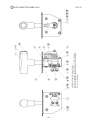
(C) MANUAL SETTING
The Credit's incremental increase settings as against a coin insertion are shown in further details
than in (B) above (refer to Table 2). Also, note that when this MANUAL SETTING is
performed, (B) COIN CREDIT setting becomes ineffective.
MANUAL SETTING
COIN ASSIGNMENTS
MANUAL SETTING
COIN TO CREDIT
1
BONUS ADDER
NO BONUS ADDER
COIN CHUTE #1 MULTIPLIER
1 COIN COUNT AS 1 COIN
COIN 1 2 3 4 5 6 7 8 9
CREDIT 1 2 3 4 5 6 7 8 9
(D)
(E)
(F)
COIN CHUTE #2 MULTIPLIER
1 COIN COUNT AS 1 COIN
COIN 1 2 3 4 5 6 7 8 9
CREDIT 1 2 3 4 5 6 7 8 9
(F)
SEQUENCE SETTING
(G)
->EXIT
SELECT WITH SERVICE BUTTON
AND PRESS TEST BUTTON
(D) COIN TO CREDIT
Determines COIN/CREDIT setting.
(E) BONUS ADDER
This sets how many coins should be inserted to obtain one SERVICE COIN.
(F) COIN CHUTE (# 1 / # 2) MULTIPLIER
This sets how many tokens one coin represents.
41
Table 1: COIN/CREDIT SETTING (COIN CHUTE COMMON TYPE)
1
1
1
1
1
1
1
1
1
1
1
2
1
1
1
2
1
COIN CHUTE 1
COIN
1 CREDIT
COIN
2 CREDITS
COIN
3 CREDITS
COIN
4 CREDITS
COIN
5 CREDITS
COIN
2 CREDITS
COIN
5 CREDITS
COIN
3 CREDITS
COIN
4 CREDITS
COIN
5 CREDITS
COIN
6 CREDITS
COINS
1 CREDIT
COIN
1 CREDIT
COIN
2 CREDITS
COIN
1 CREDIT
COINS
3 CREDITS
COIN
3 CREDITS
SETTING #20
3
4
1
2
3
4
1
COINS
COINS
COIN
COINS
COINS
COINS
COIN
SETTING #21
SETTING #22
5 COINS
1 COIN
1 CREDIT
2 CREDITS
SETTING #23
2
4
5
1
COINS
COINS
COINS
COIN
1
2
3
3
CREDIT
CREDITS
CREDITS
CREDITS
1
2
3
4
5
1
COIN
COINS
COINS
COINS
COINS
COIN
1
2
3
4
6
6
CREDIT
CREDITS
CREDITS
CREDITS
CREDITS
CREDITS
NAME OF SETTING
SETTING
SETTING
SETTING
SETTING
SETTING
SETTING
SETTING
SETTING
SETTING
SETTING
SETTING
SETTING
SETTING
SETTING
SETTING
#1
#2
#3
#4
#5
#6
#7
#8
#9
#10
#11
#12
#13
#14
#15
SETTING #16
SETTING #17
SETTING #18
SETTING #19
SETTING #24
SETTING #25
SETTING #26
SETTING #27
1
1
1
2
3
5
5
CREDIT
CREDIT
CREDIT
CREDITS
CREDITS
CREDITS
CREDITS
FREE PLAY
42
1
1
1
1
1
1
1
1
1
1
1
2
2
2
1
2
1
2
3
4
1
2
3
4
1
2
3
4
5
3
5
2
4
5
2
4
5
1
2
3
4
5
1
2
3
4
5
COIN CHUTE 2
COIN
1 CREDIT
COIN
1 CREDIT
COIN
1 CREDIT
COIN
1 CREDIT
COIN
1 CREDIT
COIN
2 CREDITS
COIN
2 CREDITS
COIN
3 CREDITS
COIN
4 CREDITS
COIN
5 CREDITS
COIN
6 CREDITS
COINS
1 CREDIT
COINS
1 CREDIT
COINS
1 CREDIT
COIN
1 CREDIT
COINS
3 CREDITS
COIN
1 CREDIT
COINS
3 CREDITS
COINS
1 CREDIT
COINS
1 CREDIT
COIN
1 CREDIT
COINS
2 CREDITS
COINS
3 CREDITS
COINS
5 CREDITS
COIN
1 CREDIT
COINS
2 CREDITS
COINS
3 CREDITS
COINS
5 CREDITS
COINS
1 CREDIT
COINS
1 CREDIT
COINS
2 CREDITS
COINS
1 CREDIT
COINS
2 CREDITS
COINS
3 CREDITS
COINS
1 CREDIT
COINS
2 CREDITS
COINS
3 CREDITS
COIN
1 CREDIT
COINS
2 CREDITS
COINS
3 CREDITS
COINS
4 CREDITS
COINS
6 CREDITS
COIN
1 CREDIT
COINS
2 CREDITS
COINS
3 CREDITS
COINS
4 CREDITS
COINS
6 CREDITS
FREE PLAY
Table 2: MANUAL SETTING
COIN TO CREDIT
1
2
3
4
5
6
7
8
9
BONUS ADDER
NO BONUS ADDER
2 COINS GIVE 1
3 COINS GIVE 1
4 COINS GIVE 1
5 COINS GIVE 1
6 COINS GIVE 1
7 COINS GIVE 1
8 COINS GIVE 1
9 COINS GIVE 1
COIN CHUTE (# 1 / # 2)
MULTIPLIER
1
1
1
1
1
1
1
1
1
43
COIN
COINS
COINS
COINS
COINS
COINS
COINS
COINS
COINS
1 CREDIT
1 CREDIT
1 CREDIT
1 CREDIT
1 CREDIT
1 CREDIT
1 CREDIT
1 CREDIT
1 CREDIT
EXTRA COIN
EXTRA COIN
EXTRA COIN
EXTRA COIN
EXTRA COIN
EXTRA COIN
EXTRA COIN
EXTRA COIN
COIN COUNTS AS
COIN COUNTS AS
COIN COUNTS AS
COIN COUNTS AS
COIN COUNTS AS
COIN COUNTS AS
COIN COUNTS AS
COIN COUNTS AS
COIN COUNTS AS
1
2
3
4
5
6
7
8
9
COIN
COINS
COINS
COINS
COINS
COINS
COINS
COINS
COINS
(G) SEQUENCE SETTING
Number of credits required for starting game, etc. can be set.
Each sequence can be set between 1 ~ 5 credit(s).
COIN ASSIGNMENTS
SEQUENCE SETTING
SEQUENCE 1 1 CREDIT(S)
SEQUENCE 2 1 CREDIT(S)
SEQUENCE 3 1 CREDIT(S)
SEQUENCE 4 1 CREDIT(S)
SEQUENCE 5 1 CREDIT(S)
SEQUENCE 6 1 CREDIT(S)
SEQUENCE 7 1 CREDIT(S)
SEQUENCE 8 1 CREDIT(S)
-> EXIT
[XXXXXXXXXXXXXXXXXXXX]
DESCRIPTION OF SEQUENCE
1 CREDIT TO START
2 CREDIT TO CONTINUE
3 NO USE
4 NO USE
5 NO USE
6 NO USE
7 NO USE
8 NO USE
SELECT WITH SERVICE BUTTON
AND PRESS TEST BUTTON
(EXAMPLE)
In cases of video games such as SEGA STRIKE FIGHTER :
SEQUENCE 1 :
Number of credits required for game start (initial value=2)
SEQUENCE 2 :
Number of credits required for CONTINUE (initial value=1)
SEQUENCE 3 ~ 8 : NOT USED.
44
7 BOOKKEEPING
• BOOKKEEPING 1/2
This allows such data as operating time/No. of coins inserted/ No. of credits to be checked.
Perform work by watching the front monitor only.
BOOKKEEPING 1/2
TOTAL TIME
0D 00H 00M 00S
CREDIT
0
(A)
COIN
COIN
COIN
COIN
0
0
0
0
(B)
1
2
3
4
TOTAL COIN
COIN CREDIT
SERVICE CREDIT
TOTAL CREDIT
0
0
0
0
PRESS TEST BUTTON TO CONTINUE
(A) CREDIT 1,2 (,3,4)
(B) COIN 1,2 (,3,4)
Number of Display Items vary depending on the setting of CABINET TYPE in the SYSTEM
ASSIGNMENTS.
Press the TEST button to proceed to BOOKKEEPING 2/2.
• BOOKKEEPING 2/2
Each sequence displays the frequency of functioning. The contents of each sequence vary
depending on specific games.
Display Items vary depending on the setting of CABINET TYPE in the SYSTEM
ASSIGNMENTS.
Perform work by watching the front monitor only.
BOOKKEEPING 2/2
P1 SEQ 1
P1 SEQ 2
P1 SEQ 3
P1 SEQ 4
P1 SEQ 5
P1 SEQ 6
P1 SEQ 7
P1 SEQ 8
0
0
0
0
0
0
0
0
PRESS TEST BUTTON TO EXIT
(EXAMPLE) In cases of video games such as SEGA STRIKE FIGHTER :
P1(P2) SEQ 1 : Frequency of Game Start by the player.
P1(P2) SEQ 2 : Frequency of CONTINUE by Player (Player 2)
P1(P2) SEQ 3 ~ 8 : NOT USED.
45
8 BACKUP DATA CLEAR
Clears the contents of BOOKKEEPING (SYSTEM TEST MODE).
BACKUP DATA CLEAR
YES(CLEAR)
-> NO(CANCEL)
SELECT WITH SERVICE BUTTON
AND PRESS TEST BUTTON
When clearing, bring the arrow to YES by using the SERVICE button and press the TEST
button. Bring the arrow to NO and press the TEST button to have the menu mode return
without clearing the data. COMPLETED is displayed when clearing is completed. Press the
TEST button to return to the menu mode.
9 CLOCK SETTING
Set YEAR, MONTH, DAY, HOUR, and MINUTE for NAOMI Main BD.
CLOCK SETTING
1998 12/02 14:30 33 WED
YEAR
MONTH
DAY
HOUR
MINUTE
-> EXIT
SELECT WITH SERVICE BUTTON
AND PRESS TEST BUTTON
Select the desired item with the SERVICE button and press the TEST button to increase the
value. Upon finishing the SETTING, bring the arrow to EXIT and press the TEST button to
return to the menu mode.
46
10 ROM BOARD TEST
In this test, on-ROM-BD ROM check is executed. If GOOD is displayed, it is satisfactory.
However, Program ROMs (IC22 or IC 1) do not display GOOD or BAD.
BYTE and WORD refers to the check sum of each unit.
When testing, watch the front monitor only.
ROM BOARD TEST
[XXXXXXXXXXXXXXXXX]
NO. TYPE RESULT BYTE WORD
IC22 32M ---- XXXX XXXX
IC1 64M GOOD XXXX XXXX
IC2 64M GOOD XXXX XXXX
IC3 64M GOOD XXXX XXXX
IC4 64M GOOD XXXX XXXX
IC5 64M GOOD XXXX XXXX
IC6 64M GOOD XXXX XXXX
IC7 64M GOOD XXXX XXXX
IC8 64M GOOD XXXX XXXX
IC9 64M GOOD XXXX XXXX
IC10 64M GOOD XXXX XXXX
IC11 64M GOOD XXXX XXXX
•••• ••• •••• •••• ••••
IC20 64M GOOD XXXX XXXX
PRESS TEST BUTTON TO EXIT
The number of ROMs depends on each game.
Press the TEST button to return to the menu mode.
11 GAME TEST MODE
Selecting this item enables you to open the SEGA STRIKE FIGHTER TEST MENU screen
where you can test the input devices that are specific with the game and set the difficulty level.
For further information see the section 9-3.
47
9 - 3 GAME TEST MODE
A. MENU MODE
SYSTEM MENU
SEGA STRIKE FIGHTER TEST MENU
RAM TEST
JVS TEST
SOUND TEST
C.R.T. TEST
SYSTEM ASSIGNMENTS
COIN ASSIGNMENTS
BOOKKEEPING
BACKUP DATA CLEAR
CLOCK SETTING
INPUT TEST
OUTPUT TEST
C.R.T. TEST
GAME ASSIGNMENTS
VOLUME SETTING
BOOKKEEPING
BACKUP DATA CLEAR
-> EXIT
ROM BOARD TEST
-> GAME TEST MODE
[XXXXXXXXXXXXXXXXXXX]
EXIT
SELECT WITH SERVICE BUTTON
AND
PRESS TEST BUTTON
SELECT WITH SERVICE BUTTON
AND PRESS TEST BUTTON
SYSTEM TEST MODE MENU
GAME TEST MODE MENU
FIG. 9. 3 a MENU MODE
• Connect the power and press the start button. After performing a power-on test of the game
board, the system displays the SYSTEM MENU screen.
• By pressing the SERVICE button, move the arrow (->) to select the GAME TEST MODE.
• Press the TEST button to enter GAME TEST MODE. The screen displays the GAME TEST
MODE MENU.
• By pressing the SERVICE button, move the arrow (->) to select the desired item . Press the
TEST button to execute the selected item.
• Select EXIT and press the TEST button to exit from the GAME TEST MODE and return to
the SYSTEM TEST MODE MENU. Further, select EXIT and press the TEST button to
finish SYSTEM TEST MODE and return to the normal mode.
48
B. INPUT TEST
Selecting INPUT TEST displays the following and allows the status of each switch to be
checked and the Volume value of each operative unit to be observed. In this mode, periodically
check the status of each switch and Volume.
INPUT TEST
GUN TRIGGER
OFF
MISSILE BUTTON
OFF
AIR BRAKE
OFF
VIEW CHANGE
OFF
VIEW UP
OFF
VIEW BACK
OFF
VIEW LEFT
OFF
VIEW RIGHT
OFF
START BUTTON
OFF
SERVICE
OFF
TEST
OFF
CONTROL STICK(AILERON) ABH
CONTROL STICK(ELEVATOR) ABH
RUDDER PEDAL
ABH
THRUST LEVER
ABH
PRESS TEST AND SERVICE BUTTON TO EXIT
FIG. 9. 3 b INPUT TEST
• By pressing each switch, if the display on the right-hand side of the name of each switch
changes to ON from OFF, the SW and the wiring connections are satisfactory.
• Operate CONTROL WHEEL, THRUST LEVER, etc. to check Volume value display
variation. If the variation is not satisfactorily consistent with operation, refer to Sections 10
and 11.
Operation of each control changes its volume value as follows:
Volume Value
Becoming smaller
Becoming larger
Control Stick (aileron)
Tilt leftward.
Tilt rightward.
Control Stick (elevator)
Tilt forward.
Tilt backward.
Rudder Pedal
Step on the right one.
Step on the left one.
Thrust Lever
Push.
Pull.
• Simultaneously pressing the SERVICE button and the TEST button returns the Test Menu
on the screen.
49
C. OUTPUT TEST
Selecting OUTPUT TEST displays the following on the monitor and allows the status of Lamp
to be checked. In this mode, periodically check the lamp status.
Make sure that when the value of the BASS SHAKER item is ON the bass shaker (vibrator)
sounds.
OUTPUT TEST
START BUTTON LAMP
VIEW CHANGE LAMP
WARNING LAMP
BASS SHAKER
-> EXIT
OFF
OFF
OFF
OFF
SELECT WITH SERVICE BUTTON
AND PRESS TEST BUTTON
FIG. 9. 3 c OUTPUT TEST
• Select the item with the SERVICE button and press the TEST button to alternate the display
to and from ON and OFF. Outputting is to correspond to the ON/OFF alternation.
• When exiting from OUTPUT TEST with ON display, all of ON displays change to OFF.
• Bring the arrow to EXIT and press the TEST Button to return to the menu mode.
50
D. C.R.T. TEST
Selecting C.R.T. test causes the monitor to display the following and allows the 3 screens
(displayed simultaneously) to adjust brightness balance.
C.R.T. TEST
Press the TEST Button to return
to the menu mode.
PRESS TEST BUTTON TO EXIT
FIG. 9. 3 d C.R.T. TEST
E. GAME ASSIGNMENTS
When GAME ASSIGNMENTS are selected, the following appears on the monitor and Game
Difficulty, etc. can be set. The setting change is not renewed until the TEST mode is exited.
After setting change, be sure to exit from the TEST mode.
GAME ASSIGNMENTS
GAME DIFFICULTY #1
GAME DIFFICULTY #2
NORMAL
NORMAL
-> EXIT
SELECT WITH SERVICE BUTTON
AND PRESS TEST BUTTON
FIG. 9. 3 e GAME ASSIGNMENTS
The GAME DIFFICULTY #1 item is to set the difficulty of the training (for the beginners). The
GAME DIFFICULTY #2 item is to set the difficulty of the OPERATION DESERT FIRE (for
the intermediates) and the OPERATION RED ROCK (for the experts).
There are 5 levels of difficulty: VERY EASY, EASY, NORMAL, HARD, VERY HARD. The
higher the level, the shorter the limit of a playing time; and vice versa.
Bring the arrow to EXIT and press the TEST Button to return to the menu mode.
51
F. VOLUME SETTING
Selecting VOLUME SETTING causes the following to be displayed on the monitor and allows
each Control Unit's Volume to be set.
If operability is unsatisfactory, or when adjusting or replacing the Volume, set the Volume in
this mode.
VOLUME SETTING
MIN
50H
(20H)
CONTROL STICK(ELEVATOR) 50H
(20H)
RUDDER PEDAL
50H
(20H)
THRUST LEVER
50H
(20H)
CONTROL STICK(AILERON)
MAX NUE
80H BFH
(DFH) (B0H)
80H BFH
(DFH) (B0H)
80H BFH
(DFH) (B0H)
80H BFH
(DFH) (B0H)
EXIT WITH SAVE
-> EXIT WITHOUT SAVE
SELECT WITH SERVICE BUTTON
AND PRESS TEST BUTTON
FIG. 9. 3 f VOLUME SETTING
Method of volume setting
The screen shows the present settings in the brackets. Operate each control within its movable
range. This action enables to newly input the maximum and minimum settings. Return the
control stick and thrust lever to their neutral, central positions. Return the rudder pedals to their
original positions. And then select the EXIT WITH SAVE item and press the TEST button; the
new settings are saved in the system. (If you select the EXIT WITHOUT SAVE item and press
the TEST button, the new settings are not saved.)
52
G. BOOKKEEPING
Selecting BOOKKEEPING allows the data of operating status in 2 pages.
Each time the TEST button is pressed, the ensuing page appears. Pressing the TEST button
while the second page is displayed causes the Menu mode to return on the screen.
BOOKKEEPING 1/2
PLAY TIME
AVERAGE PLAY TIME
LONGEST PLAY TIME
SHORTEST PLAY TIME
PLAY TIME:
Refers to the game play time.
0D 0H 0M 0S
0D 0H 0M 0S
0D 0H 0M 0S
0D 0H 0M 0S
PRESS TEST BUTTON TO CONTINUE
FIG. 9. 3 g a BOOKKEEPING (1/2)
BOOKKEEPING 2/2
In Page 2/2, Histogram of Number of Play
as against Play Time is displayed. For
setting the DIFFICULTY, refer to this
histogram.
TIME HISTOGRAM
0M00S - 0M29S
0M30S - 0M59S
1M00S - 1M29S
1M30S - 1M59S
2M00S - 2M29S
2M30S - 2M59S
3M00S - 3M29S
3M30S - 3M59S
4M00S - 4M29S
4M30S - 4M59S
5M00S - 5M29S
5M30S - 5M59S
6M00S - 6M29S
6M30S - 6M59S
7M00S - 7M29S
7M30S - 7M59S
8M00S - 8M29S
8M30S - 8M59S
9M00S - 9M29S
9M30S - 9M59S
OVER 10M00S
0
0
0
0
0
0
0
0
0
0
0
0
0
0
0
0
0
0
0
0
0
PRESS TEST BUTTON TO EXIT
FIG. 9. 3 g b BOOKKEEPING (2/2)
By-playtime play frequency bookkeeping is displayed in increments of 30 seconds from 0M00S
to 9M59S. Playtime in excess of 10 minutes is displayed all in the category of OVER 10 M00S.
53
H. BACKUP DATA CLEAR
This allows the contents of BOOKKEEPING and the Ranking data to be cleared. Despite the
"clear" execution, the settings of GAME ASSIGNMENTS do not change.
BACKUP DATA CLEAR
YES(CLEAR)
-> NO (CANCEL)
SELECT WITH SERVICE BUTTON
AND PRESS TEST BUTTON
FIG. 9. 3 h BACKUP DATA CLEAR
When clearing, use the SERVICE button to bring the arrow (ÅÑ) to "YES (CLEAR)" and press
the TEST button. When the data has been cleared, "COMPLETED" will be displayed. Bring
the arrow to "NO (CANCEL)" and press the TEST button to return to the Menu mode without
clearing the data.
54
10. CONTROL PANEL
Before starting to work, ensure that the Power SW is OFF. Failure to observe
this can cause electric shock or short circuit.
Use care so as not to damage wirings. Damaged wiring can cause electric
shock or short circuit.
Do not touch undesignated places. Touching places not designated can cause
electric shock or short circuit.
This work should be performed by the Location's Maintenance Man or
Serviceman. Performing work by non-technical personnel can cause electric
shock hazard.
Do not perform work other than those specified in this Manual in order to
prevent accidents during performing work and operation after performing
work. Performing work not specified in this Manual may require special
training for this product. If performing work other than those stated in this
manual is required for repair, contact the offices herein stated in this manual
or where you purchased the product from and ask for repair or inquire how to
repair.
Be very careful when soldering. Handling a soldering iron carelessly may
result in a fire or a burn.
Be careful when heating the heat-shrinkable tubing. Heating it carelessly may
result in a fire or a burn.
When opening or closing the control panel, do so slowly with using your both
hands to hold it. The control panel may be closed by itself due to its own
weight. If this happens, you may pinch your hands or fingers in the control
panel or be bruised.
Use care when handling the parts inside the control panel. Be careful so as
not to cause damaging, missing, or deforming the parts. Damaging small
portion of a part can cause malfunctioning.
When securing the plastic-made parts, do not excessively fasten screws and
nuts. Failure to observe this may damage the parts and cause injury due to
fragments resulting from damage.
This game machine is equipped with the control panel and the pedal units, each used as an
operating and inputting device when you are playing the game. The control panel provides the
control stick, thrust lever, view-change lever, start button, and view change button. The gun
button and the missile button are mounted on the control stick while the air brake button on the
thrust lever.
Test these devices monthly and make sure that they perform normally. If any one of them
performs abnormally, reset its volume values on the VOLUME SETTING screen. If the
problem is still reproduced, then fix it because it may be failed.
55
10 - 1 OPENING THE CONTROL PANEL
Open the control panel in the following procedure when servicing any one of the input devices
on the control panel (resetting the volume value, replacing some parts, greasing, etc.).
TAMPERPROOF SCREW (4) black
M5 X 10, flat washer used.
1 Disconnect the power.
2 Remove the 4 tamperproof screws.
PHOTO 10. 1 a
3 Open the control panel with using
your both hands to securely hold it.
The control panel may be closed
by itself due to its own weight.
Keep holding the control panel
securely, therefore, until the
internal chain is tensed to support
it. Be careful not to release your
hands from the control panel
earlier; otherwise you may pinch
your hands or fingers in the control
panel or be bruised.
56
PHOTO 10. 1 b
10 - 2 REPLACING THE VOLUME OF THE CONTROL SITCK (an analog joystick)
If the control stick operates unsatisfactorily, reset its volume values on the VOLUME
SETTING screen. If the problem is still reproduced, then replace the volume because it may be
failed.
Remove the control stick from the control panel, and then replace the volume in the underdescribed procedure.
CAUTION: Remove the control stick from the control panel before proceeding to replace the
volume. Failure to do so may cause the wires to be damaged and the wire covers to be melted.
Therefore, do not fail to observe this important instruction.
Prepare the following tools:
Wrench (a standard accessory) or screwdriver for tamperproof screws; Phillips head
screwdriver; Wrenches or screwdrivers for hexagon nuts of 8 mm and 12 mm in width across
flats; Nippers; Cutter; Wire strippers; Soldering iron; Industrial-use dryer.
Disconnect the connector.
1 Disconnect the power, and open
the control panel. (See the
section 10-1.)
2 Unclamp the wires around the
control stick. Then disconnect
the control stick's 2 wire
connectors.
PHOTO 10. 2 a
HEXAGON NUT (4)
M5
3 Remove the 4 hexagon nuts.
4 Detach the control stick from
the control panel. Be careful not
to damage the wires.
PHOTO 10. 2 b
57
5 Remove the 2 screws. Detach
the volume with the bracket
from the control stick.
SCREW (2)
M3 X 30, w/spring washer
VOLUME
220-5737
PHOTO 10. 2 c
Remove the hexagon nut.
6 Remove the hexagon nut that
fixes the volume onto the
bracket. Detach the volume
from the bracket.
PHOTO 10. 2 d
58
Nip the wires.
7 Use the nippers to nip the wires
off the volume. Select a nipping
position that is as closely as
possible to the volume, because
the wires will be reused.
8 Remove the present heatshrinkable tubings from the
wires.
PHOTO 10. 2 e
Strip the covers.
9 Use the wire strippers to strip
the covers of the wires. Expose
the end of the conductors about
5 mm.
PHOTO 10. 2 f
Insert the wires into
heat-shrinkable tubings.
10 Insert each wire into a heatshrinkable tubing (a standard
accessory).
59
PHOTO 10. 2 g
11 Solder the wires onto the new
volume's terminals. Carefully
read the wiring connection
diagram and thereby solder
correctly.
VOLUME
220-5737
Solder the wires.
PHOTO 10. 2 h
12 Heat the heat-shrinkable
tubings, with the industrial-use
dryer, so that they can closely
cover the soldered sections.
PHOTO 10. 2 i
13 Attach the volume onto the bracket. Fasten the 2 screws to mount the volume with the bracket
onto the control stick body.
14 Attach the control stick onto the control panel.
15 Connect the power, and set the volume on the VOLUME SETTING screen.
(See the Section 9-3.)
16 Test the volume on the INPUT TEST screen, and make sure that the volume values change
smoothly according to the operation of the control stick.
60
10 - 3 REPLACING THE CONTROL STICK'S MICROSWITCH
If the gun button or missile button operates unsatisfactorily, replace the microswitch in the
control stick because it may be failed.
Remove the control stick from the control panel, and then replace the microswitch (and any
other parts inside the control stick's grip, too) in the under-described procedure.
CAUTION: Remove the control stick from the control panel before proceeding to replace the
microswitch. Failure to do so may cause some parts to be lost and the replacement work to be
harder. Therefore, observe this 'troublesome' but important instruction.
Prepare the following tools:
Wrench (a standard accessory) or screwdriver for tamperproof screws; Phillips head
screwdriver; Wrench or screwdriver for hexagon nuts of 8 mm in width across flats; Soldering
iron.
1 Disconnect the power, open the
control panel, and detach the
control stick. (See the section
10-2.)
2 Push down the rubber cover on
the control stick's root.
PHOTO 10. 3 a
3 Remove the 3 tamperproof
screws to detach the grip cover
B. Be careful not to lose the
parts inside the grip because
they are now detachable.
GRIP COVER B
TAMPERPROOF SCREW (3)
M4 X 8, spring washer used.
GRIP COVER A
PHOTO 10. 3 b
61
4 Remove the tapping screws, 2 each for a microswitch, to detach the 2 microswitches from grip
cover A.
TAPPING SCREW (2)
2 X 12
Gun Button with an Actuator
509-5975
Missile Button without an Actuator
509-5974
PHOTO 10. 3 c
5 Use the soldering iron to unsolder the wires from the present microswitch's terminals.
6 Solder the wires onto the new microswitch's terminals.
7 Fasten the tapping screws, 2 each for a microswitch, to attach the 2 microswitches onto grip
cover A. Be careful not to fasten them too tightly because doing so may damage the
microswitches and/or the screw holes of the grip cover A.
8 Fasten the 3 tamperproof screws to attach the grip cover B. Be careful not to fasten them too
tightly.
9 Attach the control stick on the control panel.
10 Connect the power. Test the gun and missile buttons on the INPUT TEST screen (See the
Section 9-3.), and make sure that they can operate normally.
62
10 - 4 ADJUSTING AND REPLACING THE VOLUME OF THE THRUST LEVER
If the thrust lever operates unsatisfactorily, reset its volume values on the VOLUME SETTING
screen. If the problem is still reproduced, then adjust the gears because the gears may be poorly
engaged, or replace the volume because it may be failed.
Readjust the engagement of the gears or replace the volume in the under-described procedure.
Prepare the following tools:
Wrench (a standard accessory) or screwdriver for tamperproof screws; Phillips head
screwdriver; Slotted-head screwdriver; Wrench for hexagon nuts of 11 mm in width across flats;
Soldering iron.
SCREW (2)
M4 X 8, w/flat & spring washers
Adjusting the Volume
1 Disconnect the power, and open
the control panel. (See the section
10-1.)
2 Loosen the 2 screws that fix the
thrust lever's VR bracket, and thus
disengage the gears.
PHOTO 10. 4
3 Place the thrust lever in a neutral
middle position. Engage the gears
so that the volume shaft's D-cut
end faces as specified by the
Figure 10.4a.
4 Fasten the 2 screws that fix the
thrust lever's VR bracket.
5 Connect the power, and set the
volume on the VOLUME
SETTING screen. (See the Section
9-3.)
6 Test the volume on the INPUT
TEST screen, and make sure that
the volume values change
smoothly according to the
operation of the thrust lever.
"D"CUT FACE
7 Close the control panel.
FIG. 10. 4 a
63
Replacing the Volume
Install the replacement volume to the direction as specified by the Figure 10.4a; then the lever
can be seated within the volume shaft's rotating range. Failure to observe this instruction may
cause the volume to be damaged if you fully pull or push the lever.
1 Disconnect the power, and open the control panel. (See the section 10-1.)
2 Unclamp the wires of the present volume, and disconnect the connector.
3 Remove the 2 screws that fix the thrust lever's VR bracket, and detach the VR bracket with the
gear and volume.
4 Remove the gear and volume from the VR bracket.
5 Use the nippers to nip the wires off the volume. Select a nipping position that is as closely as
possible to the volume, because the wires will be reused.
6 Remove the present heat-shrinkable tubings from the wires.
7 Use the wire strippers to strip the covers of the wires. Expose the end of the conductors of about
5 mm.
8 Insert each wire into a heat-shrinkable tubing (a standard accessory).
9 Solder the wires onto the new volume's terminals.
10 Heat the heat-shrinkable tubings, with the industrial-use dryer, so that they can closely cover the
soldered sections.
11 Attach the volume onto the bracket and fix the gear onto the volume shaft.
VOLUME
220-5373,220-5484
CHEESE HEAD SCREW (2)
M3 X 8
HEAT-SHRINKABLE TUBING
GEAR
NUT AND WASHER
(the volume's standard accessories)
VR BRACKET
FIG. 10. 4 b
12 Place the thrust lever in a neutral middle position. Engage the gears so that the volume shaft's
D-cut end faces as specified by the Figure 10.4a.
13 Fasten the 2 screws that fix the thrust lever's VR bracket.
14 Connect the connector and clamp the wires.
15 Connect the power, and set the volume on the VOLUME SETTING screen. (See the Section 93.)
16 Test the volume on the INPUT TEST screen, and make sure that the volume values change
smoothly according to the operation of the thrust lever.
17 Close the control panel.
64
10 - 5 GREASING
STOP
IMPORTANT
Be sure to use the designated grease. Using undesignated grease can cause
parts damage.
Do not apply greasing to undesignated places. Failure to observe this can
cause malfunctioning or quality deterioration of parts.
The period for greasing specified herein is a standard. Apply greasing to the
specified portions as occasion arises.
Every 3 months grease on the following sections:
Thrust lever : the volume gear's engaging surfaces and the spring, and
Control stick : the contacting surfaces and the spring.
Use the spray-type grease: either the Grease Mate (part number: 090-0066) or the Grease 248
(part number: 090-0070) specified by the Sega. If these are not available, use the alternative one
that is applicable for heat-resistant and cold-resistant plastics.
VOLUME GEAR MESH PORTION
Thrust lever
SPRING PORTION
Thrust lever
SPRING PORTION
Control stick
CONTACT FACE PORTION
Control stick
PHOTO 10. 5
65
10 - 6 REPLACING THE GUIDE PLATE OF THE CONTROL STICK
If the control stick operates unsatisfactorily, replace the guide plate because it may be worn or
scratched.
Replace the guide plate in the under-described procedure.
Prepare the following tools:
Wrench (a standard accessory) or screwdriver for tamperproof screws; Wrench for hexagon
socket head screws of 4 mm in width across flats.
1 Disconnect the power, and open the control panel. (See the section 10-1.)
2 Remove the 4 hexagon socket head screws that fix the guide plate, and replace the guide plate.
HEXAGON SOCKET HEAD SCREW (4)
M5 X 35, spring washer used.
GUIDE PLATE
253-5496
PHOTO 10. 6
66
11. PEDAL UNIT
First, be sure to turn power off before performing work. Failure to observe
this can cause electric shock and short circuit accidents.
Use care so as not to damage wirings. Damaged wiring can cause electric
shock and short circuit.
Do not touch undesignated places. Touching places not designated can cause
electric shock and short circuit.
This work should be performed by the Location's Maintenance Man or
Serviceman. Performing work by non-technical personnel can cause electric
shock.
If the rudder pedals' volume values abnormally change on the INPUT TEST screen, adjust or
replace their volumes.
PEDAL MECHANISM COVER
11 - 1 ADJUSTING THE VOLUME
1 Take out the 4 screws and remove
the Pedal Mechanism Cover.
TRUSS SCREW (4) black
M4 X 8
FIG. 11. 1
2 Loosen the 2 screws securing each
Volume Bracket and move the Volume
Brackets.
ADJUST GEAR
VOLUME
220-5373,5484
VOLUME BRACKET
3 Move the Volume Bracket to disengage
gear mesh. Move the Volume Shaft in
the manner so that the cut portion of the
Volume Shaft faces opposite the center
of ADJUST GEAR.
4 Engage the gears and fasten the 2 screws.
5 Carefully move the Pedal forward &
backward and check to ensure that the
Volume range is not exceeded.
SCREW (2)
M4 X 10, w/flat & spring washers
6 Upon completion of adjustment, be sure
to perform Volume setting in the TEST
mode.
PHOTO 11. 1
67
11 - 2 REPLACING THE VOLUME
First, be sure to turn power off before performing work. Failure to observe
this can cause electric shock and short circuit accidents.
Be very careful when soldering. Handling a soldering iron carelessly may
result in a fire or a burn.
Be careful when heating the heat-shrinkable tubing. Heating it carelessly may
result in a fire or a burn.
1 Remove the Volume Gear from the Volume to replace the Volume.
2 After replacing the Volume, make adjustment as per the procedure of 11-1 ADJUSTING THE
VOLUME.
11 - 3 GREASING
First, be sure to turn power off before performing work. Failure to observe this
can cause electric shock and short circuit accidents.
STOP
IMPORTANT
Be sure to use the designated grease. Using undesignated grease can cause
parts damage.
Do not apply greasing to undesignated places. Failure to observe this can
cause malfunctioning or quality deterioration of parts.
Apply greasing to the following portions once every three (3) months.
For Spray Grease, use NOK GLUBER L60 or GREASE MATE (PART No. 090-0066).
GEAR MESH PORTION
PHOTO 11. 3
68
12. COIN SELECTOR
HANDLING THE COIN JAM
If the coin is not rejected when the REJECT button is pressed, open the coin chute door and
open the selector gate. After removing the jammed coin, put a normal coin in and check to see
that the selector correctly functions.
GATE
CLEANING THE COIN SELECTOR
Remove and clean smears by using a
soft cloth dipped in water or diluted
chemical detergent and then
squeezed dry.
Never apply machine oil, etc. to the
Coin Selector.
After cleaning the Coin Selector,
insert a regular coin in the normal
working status and ensure that the
Selector correctly functions.
STOP
IMPORTANT
1
2
3
4
5
6
The coin selector should be cleaned once every
3 months. When cleaning, follow the procedure
below:
Turn the power for the machine OFF. Open the
coin chute door.
Open the gate and dust off by using a soft brush
(made of wool, etc.).
Remove and clean smears by using a soft cloth
dipped in water or diluted chemical detergent
and then squeezed dry.
Remove the CRADLE.
When removing the retaining ring
(E ring), be very careful so as not to bend the
rotary shaft.
Remove stain from the rotary shaft and shaft
receiving portions by wiping off with a soft
cloth, etc.
After wiping off as per áD above, further apply
a dry cloth, etc. to cause the coin selector to dry
completely.
COIN INSERTION TEST
Once every month, when performing the
Coin SW Test, simultaneously check the
following:
Does the Coin Meter count satisfactorily?
Does the coin drop into the Cashbox
correctly?
Is the coin rejected when inserted while
keeping the Reject Button pressed down?
FIG. 12 a
CRADLE
FIG. 12 b
Insert a coin
while keeping the
Reject Button
pressed down and
check if it is
rejected.
COIN METER
FIG. 12 c
69
13. MONITOR
13 - 1 CAUTIONS AND WARNINGS CONCERNING THE SAFETY FOR HANDLING THE MONITORS
Before handling the monitors, be sure to read the following explanations and comply with the
caution/warning instructions given below. Note that the caution/warning symbol marks and
letters are used in the instructions.
Indicates that handling the monitors
erroneously by disregarding this warning may
cause a potentially hazardous situation,
which could result in death or serious injury.
Indicates that handling the monitors by
disregarding this caution may cause a
potentially hazardous situation, which could
result in personal injury and or material
damage.
Indicates that access to a specific part of the
equipment is forbidden.
Indicates the instruction to disconnect a
power connector or to unplug.
When performing such work as installing and removing the monitor, inserting and disconnecting
the external connectors to and from monitor interior and the monitor, be sure to disconnect the
power connector (plug) before starting the work. Proceeding the work without following this
instruction can cause electric shock or malfunctioning.
Using the monitor by converting it without obtaining a prior permission is not allowed. SEGA
shall not be liable for any malfunctioning and accident caused by said conversion.
Primary side and Secondary side
SECONDARY SIDE
The monitor's circuit which is divided into the Primary side
(Chassis, CRT)
and Secondary side, is electrically isolated. Do not touch the
primary side, or do not touch both the primary side and the
PRIMARY
secondary side simultaneously. Failing to observe the
SIDE
instruction can cause electric shock and this is very
dangerous. When making monitor adjustments, use a nonconductive driver and make adjustment without touching any
part other than the Adjustment V. R. and knob. Also, be sure
not to cause a short-circuit to the Primary side and Secondary
side. If short-circuited, it can cause electric shock or
malfunctioning, which is very dangerous.
High-tension Voltage
Some of the parts inside monitor are subject to high-tension voltage in excess of 20,000 volts and
very dangerous. Therefore, do not touch the monitor interior. Should soldering & paper wastes,
etc. be mixed in the monitor interior, turn the power off so as not to cause malfunctioning or fire
hazard.
ANODE CAP
PRIMARY SIDE
ANODE LEAD
Approx. 29 kV
DEMAGNETIZER
COIL
REAR PART
MAIN BD
FOCUS LEAD
(black)
Approx. 10 kV
DEMAGNETIZER
COIL
NECK PCB
Approx.
10 kV
SECONDARY SIDE
(Chassis, sheet metal work, CRT, etc.)
Disconnect or unplug
FBT Approx.
29 kV
Connecting the CRT and PCB
For combining the CRT and PCB, use the specified part No. to maintain the status of adjustments
made at the factory. The anode of the CRT itself will be accumulatively charged as time elapses,
generating high-tension voltage which is very dangerous. The monitor should be used with the
Chassis, CRT and PCB assembled. When repair, etc. is required at the time of malfunctioning,
be sure to send it in an "as is assembled" condition. If these are disassembled, what's charged to
said high tension voltage can be discharged, causing a very hazardous situation. Therefore, under
no circumstances should it be disassembled.
Static Electricity
Touching the CRT surface sometimes causes you to slightly feel electricity. This is because the
CRT surfaces are subject to static and will not adversely affect the human body.
Installation and removal
Ensure that the Magnetizer Coil, FBT (Fly-Back Transformer), Anode Lead and Focus Lead are
not positioned close to the sheet metal work's sharp edges, etc. and avoid damaging the insulated
portions so as not to cause electric shock and malfunctioning. (For the name of parts, refer to the
above Figures).
70
For the purpose of static prevention, special coating is applied to the CRT face of
this product. To protect the coating, pay attention to the following points.
Damaging the coating film can cause electric shock to the customers.
Do not apply or rub with a
hard item (a rod with
pointed edge, pen, etc.) to
or on the CRT surfaces.
Avoid applying stickers,
seals, etc. on the CRT face.
Aluminum Foil
Do not remove aluminum
foils from the CRT corners.
Removing the aluminum
foils can cause static
prevention effects to be
lowered.
13 - 2 CAUTIONS TO BE HEEDED WHEN CLEANING THE CRT SURFACES
Static preventive coating is applied to the CRT surfaces. When cleaning, pay
attention to the following points. Peeling off of static preventive coat can cause
electric shock.
Remove smears by using a dry, soft cloth (flannels, etc.). Do not use a coarse
gauze, etc.
For smear removing solvent, alcohol (ethanol) is recommended. When using
chemical detergent, be sure to follow instructions below:
• Dilute chemical detergent with water and dip a soft cloth in and then
thoroughly wring it to wipe smears off.
• Do not use a chemical detergent containing an abradant, powder or bleaching
agent.
• Do not use alkaline chemical detergents such as "glass cleaner" available on
the market or solvents such as thinner, etc.
Do not rub or scratch the CRT face with hard items such as brushes, scrub
brush, etc.
Carefully handle the glass parts. If you handle them carelessly, you may be
injured when they are broken; and afterward you may be also injured by the
broken glass pieces.
71
Clean the monitor glass weekly - only its upper-surfaces. When you clean its under-surfaces or
the CRT surfaces, a troublesome detaching of the monitor glass is needed.
When you clean the CRT surfaces, observe the caution instructions in Page 72; thereby be
careful not to peel the antistatic coating off.
Front Monitor Glass
To detach the monitor glass, you must first remove the control panel.
1 Disconnect the power, and open
Disconnect the connector.
the control panel. (See the section
10-1.)
2 Unclamp all the wires to the
control panel. Then, disconnect all
the wire connectors.
PHOTO 13. 2 a
HEXAGON (one each)
M4, flat & spring washers used.
3 Unclamp the 2 grounding wires.
Remove the hexagon nut, 1 each
for a wire.
PHOTO 13. 2 b
72
4 Remove the 6 hexagon-head bolts that fix the control panel onto the cabinet.
HEXAGON BOLT (6 in total)
M8 X 20, w/spring washer,flat washer used.
PHOTO 13. 2 c
TAMPERPROOF SCREW (2)
M8 X 30, flat washer used.
5 Remove the 2 tamperproof screws
that fix the control panel's bottom.
PHOTO 13. 2 d
6 Draw out the control panel and
thus detach it from the cabinet.
73
PHOTO 13. 2 e
7 Remove a screw to detach the
SCREW (one each)
M4 X 16, flat washer used.
delta-shaped plate L and R. These
plates are located at the left-bottom
and right-bottom of the monitor
glass.
8 Remove the 6 truss head screws to
detach the glass holder upper
center, glass holder lower center,
and glass sashes.
PHOTO 13. 2 f
GLASS HOLDER UPPER CENTER
GLASS SASH
GLASS SASH
GLASS HOLDER LOWER CENTER
FIG. 13. 2 a
TRUSS SCREW (6 in total) black
M4 X 16, flat washer used
9 Now remove the front monitor
glass.
MONITOR GLASS
74
FIG. 13. 2 b
BOTH SIDE MONITOR GLASS
1 Take out 9 screws and remove Monitor Cover.
MONITOR COVER
TRUSS SCREW (9 in total) chrome
M4 X 10, flat washer used
PHOTO 13. 2 g
2 Take out 3 screws and remove Monitor Side Cover.
MONITOR SIDE COVER
TRUSS SCREW (3) black
M4 X 8
PHOTO 13. 2 h
75
3 Take out 2 screws to remove the Side Cover Bracket.
SIDE COVER BRACKET
SCREW (2)
M4 X 8, w/flat & spring washers
PHOTO 13. 2 i
4 Take out 2 screw to remove the Monitor Board Lid.
TRUSS SCREW (2) black
M4 X 10
MONITOR BOARD LID
PHOTO 13. 2 j
5 Pull out the Monitor Glass.
76
13 - 3 ADJUSTMENT METHOD
Monitor adjustments have been made at the time of shipment. Therefore, do
not make further adjustment without a justifiable reason. Adjusting the
monitor which contains high tension parts is a dangerous work. Also, an
erroneous adjustment can cause deviated synchronization and image fault,
resulting in malfunctioning.
When making adjustment, utilize a resinous Alignment Rod. Servicing with
bare hand or using conductive tools can cause electric shock.
Be sure to perform appropriate adjustment of the monitor (projector). For
operation of this machine, do not leave monitor's flickering or deviation as is.
Failure to observe this can have a bad influence upon the players' or the
customers' physical conditions.
To access to the Adjustment Board, remove the 2 screws and the Monitor Board Lid. The lid is
located at the upper front of the monitor.
TRUSS SCREW (2) black
M4 X 10
MONITOR BOARD LID
ADJUSTMENT BOARD
PHOTO 13. 3
For adjustment, use the Resinous Adjustment Rod.
FIG. 13. 3
77
○
1 R-GAIN ......
○
NANAO monitor: 2 0 0 - 5 9 2 7 (31K mode)
3 B-GAIN ......
○
○
○
2 G-GAIN .......... Controls colors.
4 BRIGHT .......... Controls screen brightness.
5 H. SIZE ........... Controls horizontal screen size.
7 H. POSI ........... Controls horizontal display position on screen.
8 V. SIZE ........... Controls vertical screen size.
10 V. POSI ........... Controls vertical display position on screen.
11 CONTRAST .... Adjusts image contrast.
78
14. REPLACING THE FLUORESCENT LAMP, AND LAMPS
When performing work, be sure to turn power off. Working with power on
can cause electric shock and short circuit hazards.
The Fluorescent Lamp, when it gets hot, can cause burn. Be very careful
when replacing the Fluorescent Lamp.
Be sure to use lamps of the designated rating. Using lamps of undesignated
rating can cause a fire or malfunctioning.
To perform work safely and securely, be sure to prepare a step which is in a
secure and stable condition. Performing work without using the step can
cause violent falling down accidents.
Be careful when handling the plastic made parts. Failure to observe this may
cause injury due to damage or fragments resulting from damage.
Fluorescent Lamp in Billboard
Remove Billboard Plate by taking out
4 screws, and replace Fluorescent
Lamps.
TRUSS SCREW (4) black
M4 X 16, flat washer used
BILLBOARD PLATE
When performing work,
prepare a step.
FIG. 14 a
FLUORESCENT LAMP 15W:390-5251-15-01
GLOW LAMP:390-5638-1P
PHOTO 14a
79
Warning Lamp
LAMP LID
Take out 2 screws to remove
the Lamp Lid from the side of
Billboard, and replace the
Lamp.
TRUSS SCREW (2) black
M4 X 10
LAMP 110V 30W
390-5167
FIG. 14 b
Fluorescent Lamp under Console Plate
Remove the 6 truss head screws, remove the Console Plate, and replace the fluorescent lamp.
TRUSS SCREW (6) black
M4 X 16, flat washer used.
CONSOLE PLATE
FLUORESCENT LAMP 15W:390-5251-15-01
GLOW LAMP:390-5638-1P
PHOTO 14 b
80
Start Button, View Change Button
1 Disconnect the power, and open
the control panel.
(See the section 10-1.)
2 Turn the metal ring at the root
of the button.
3 Pull the wiring connection from
the button body.
LAMP 6.3V 1W
390-5445-01
4 A lamp is in the wiring
connection. To take it out, push
it inward and turn it
counterclockwise.
PHOTO 14 c
81
15. PERIODIC INSPECTION TABLE
The items listed below require periodic check and maintenance to retain the performance of this
machine and to ensure safe business operation.
Be sure to check once a year to see if Power Cords are damaged, the plug is
securely inserted, dust is accumulated between the Socket Outlet and the
Power Plug, etc. Using the product with dust as is accumulated can cause fire
and electric shock hazards.
Periodically once a year, request the place of contact herein stated or the
Distributor, etc. where the product was purchased from, as regards the internal
cleaning. Using the product with dust as is accumulated in the interior
without cleaning can cause a fire or accident. Note that cleaning the interior
parts can be performed on a pay-basis.
TABLE 15
ITEMS
CABINET
CONTROL PANEL
PEDAL UNIT
COIN CHUTE DOOR
MONITOR
SEAT
GAME BD
INTERIOR
POWER PLUG
Cabinet surfaces
DESCRIPTION
Check Adjusters' contact with surface.
Check SW.
Check VOLUME value.
GREASING
Check VOLUME value.
Check COIN SWes.
Coin insertion test.
COIN SELECTOR cleaning.
Cleaning CRT face
Check adjustments.
Antistatic measures
Greasing to the seat rail
MEMORY TEST.
Setting check
Cleaning
Inspection and cleaning
Cleaning
PERIOD
Daily
Monthly
Monthly
Trimonthly
Monthly
Monthly
Monthly
Trimonthly
Weekly
Monthly or when moving
Bimonthly
Trimonthly
Monthly
REFERENCE
3
9
9
10 - 5
9
9
12
12
13 - 2
6, 9, 13
5
See FIG. 15
9
Annually
See above.
As occasion arises.
See below.
CLEANING THE CABINET SURFACES
If the Cabinet is badly stained, use a cloth which is dipped in the chemical detergent liquid
diluted with water and then squeezed dry. Do not use thinner, benzine, alcohol or chemical
dustcloth as they can damage the Cabinet surfaces.
82
SEAT (Greasing to Seat Rail Portion)
Move the Seat to the rearmost portion and apply
spray greasing to the portion shown at the right
once every 3 months by using NOK KLUBER L60
or GREASE MATE SEGA PART No. 090-0066.
After greasing, move the Seat a few times forward
and backward so as to allow the grease to be
applied all over uniformly. Be sure to wipe grease
which attaches to the surfaces of the PROTECT
RUBBER on the Seat Rail, or any excess grease.
83
FIG. 15
16. TROUBLESHOOTING
In order to prevent electric shock and short circuit, be sure to turn power off
before performing work.
Be careful so as not to damage wirings. Damaged wiring can cause electric
shock or short circuit.
After removing the cause of the functioning of the Circuit Protector, reinstate
the Circuit Protector. Depending on the cause of the functioning, using the
Circuit Protector as is without removing the cause can cause generation of
heat and fire hazard.
In case a problem occurs, first check wiring connector connections.
TABLE 16 a
PROBLEMS
CAUSE
COUNTERMEASURES
With Main SW
ON, no
activation.
Power is not supplied.
Securely insert the power plug into the plug
socket.
Power supply/voltage is not
correct.
Make sure that power supply/voltage is correct.
AC unit's circuit protector has
tripped due to an instantaneous
overloading.
Rectify the overloading, and reset the circuit
protector.
(see Sec. 6 3 and FIG. 16 a)
Fluorescent
lamp in
billboard cannot
be turned on.
Contacting failure of the
connectors.
Check the wires between the front cabinet and
the billboard, and tightly reconnect if required.
Fluorescent lamp or glow bulb has
reached its service life.
Replace the Fluorescent lamp or glow bulb.
(see Sec 14)
Fluorescent
lamp under
console plate
cannot be
turned on.
Contacting failure of the
connectors.
Check the wires between the front and rear
cabinets, and tightly reconnect if required.
(see Sec. 6 1 )
Fluorescent lamp or glow bulb has
reached its service life.
Replace the Fluorescent lamp or glow bulb.
(see Sec 14)
CIRCUIT PROTECTOR
CIRCUIT PROTECTOR
Functions due to the activation of
bimetal. To restore the function,
wait for approximately one minute
or longer until the bimetal cools
off. (Press the Button.)
FIG. 16 a
84
TABLE 16 b
PROBLEMS
CAUSE
COUNTERMEASURES
No sound is
emitted.
Sound volume adjustment is not
appropriate.
Adjust the sound adjustment volume of the
switch unit. (see Sec. 9-1)
Contacting failure of the
connectors.
Check the wires between the game board,
amplifier, speakers, and volumes, and tightly
reconnect if required.
Board and Amplifier
malfunctioning.
Perform the SOUND TEST and confirm
(see Sec. 9).
Sound volume adjustment is not
appropriate.
Adjust the sound adjustment volume of the
switch unit. (see Sec. 9-1)
Contacting failure of the
connectors.
Check the wires between the game board,
amplifier, speakers, and volumes, and tightly
reconnect if required.
Check the wires between the front and rear
cabinets, and tightly reconnect if required.
(see Sec. 6 1 )
APC-4300 ASSY AUDIO DX fuse
is blown due to instantaneous
overload.
After removing the cause of overload, replace
fuse. (see FIG. 16 b)
FUSE S.B 6300 MA 250V HBC CE
514-5086-6300
Board and Amplifier
malfunctioning.
Perform the OUTPUT TEST and confirm.
(see 9-3)
Monitor screen
is black
although sounds
are heard and
fluorescent
lamp is on.
Contacting failure of the video
signal connector or the monitor's
power connector.
Check the wires to the monitor and to the game
board, and tightly reconnect if required.
Monitor screen
is uneven in
color.
Affected by C. R. T.
magnetization.
Press the DEMAG. SW of SWITCH UNIT.
(see 9-1)
The color of
image on
MONITOR
screen is
incorrect.
Contacting failure of the video
signal connector.
Check the video signal connector, and correctly
and tightly reconnect if required.
Incorrect monitor adjustment.
Make appropriate adjustments. (see 13-3)
The on-screen
image of the
monitor sways
and or shrinks.
Power supply/voltage is not
correct.
Make sure that power supply/voltage is correct.
All the switches
and volumes
cannot be input.
Contacting failure of the
connectors.
Check the wires between the I/O board and
control panel, and tightly reconnect if required.
Check the power cord to the I/O board, and
tightly reconnect if required.
Woofer and
bass shaker
cannot output.
85
TABLE 16 c
PROBLEMS
CAUSE
COUNTERMEASURES
Switch of
control stick,
thrust lever, or
view change
lever cannot be
input.
Contacting failure of the
connectors.
Check the wires of the control panel, and tightly
reconnect if required.
Wires are broken.
Check if the wires to a movable part are broken
or not. Replace the broken wires if any.
When replacing, clamp the wires so that they
receive no load when a movable part is in
action.
Control stick
operates
unsatisfactorily.
Volume is incorrectly set.
Set the volume value on the VOLUME
SETTING screen. (see 9-3)
Contacting failure of the
connectors.
Check the wires of the control panel, and tightly
reconnect if required.
Volume malfunctioning.
Replace the Volume. (see 10-2)
220-5737
Malfunctioning Amplifier Board.
Contact where you purchased the product from.
Volume is incorrectly set.
Set the volume value on the VOLUME
SETTING screen. (see 9-3)
Volume is incorrectly installed or
adjusting gears are improperly
engaged.
Reinstall the volume correctly, and set the
volume value on the VOLUME SETTING
screen.
THRUST LEVER: (see 10-4)
RUDDER PEDAL: (see 11-1)
Contacting failure of the
connectors.
Check the wires to the control panel and
between the front cabinet and rudder pedals, and
tightly reconnect if required.
Volume malfunctioning.
Replace the Volume.
220-5484, 220-5373
THRUST LEVER: (see 10-4)
RUDDER PEDAL: (see 11-2)
Contacting failure of the
connectors.
Check the wires between the front cabinet and
the billboard, and tightly reconnect if required.
The lamp needs replacement.
Replace the lamp. (see Sec.14)
The lamp needs replacement.
Replace the lamp. (see Sec.14)
Rudder pedals
and thrust lever
operate
unsatisfactorily.
Warning lamps
cannot be
turned on.
Start button and
view change
button cannot
flash.
86
REPLACMENT OF FUSE
In case fuse replacements other than those stated in this manual are necessary,
contact where you purchased the product from for inquiries regarding this
matter.
Fuse replacements other than those specified can cause accidents and are
strictly forbidden.
In order to prevent an electric shock, be sure to turn power off and unplug
from the socket outlet before performing work by touching the internal parts
of the product.
Be careful so as not to damage wirings. Damaged wiring can cause electric
shock and short circuit accidents.
Be sure to use fuses meeting specified rating. Using fuses exceeding the
specified rating can cause fire and electric shock accidents.
After eliminating the cause of the blowing of fuse, replace the fuse.
Depending on the cause of fuse blowing, continued use with the fuse as is
blown can cause generation of heat and fire hazard.
Remove Side Door R by taking out 2 screws. The fuse is located at the position shown.
TRUSS SCREW (2) black
M4 X 30, flat washer used.
SIDE DOOR R
FUSE 6.3A 250W
514-5086-6300
FIG. 16 b
87
17. GAME BOARD
In order to prevent electric shock and short circuit hazards, be sure to turn
power off before performing work.
Be careful so as not to damage wirings. Damaged wiring can cause fire,
electric shock and short circuit hazards.
Do not expose the Game BD, etc. without a good reason. Failure to observe
this can cause electric shock or malfunctioning.
The electronic parts on the IC Board could be damaged due to human body's static
electricity. Before performing IC Board related work, be sure to discharge
physically accumulated statics by touching grounded metallic surfaces, etc.
STOP
IMPORTANT
Put the Game Board in the Carton Box (an accessory) together with the Shield
Case when requesting for the replacement or repair. Transporting the Game
Board in an undesignated status for replacement/repair is unacceptable.
In this manual, how to remove the Game Board is explained for convenience.
However, this work should be performed by SEGA SERVICEMAN.
17 - 1 TAKING OUT THE BOARD
1 Turn power off.
2 Take out the 2 truss screws, unlock and remove
the Back Door Lower.
3 Disconnect all of the Connectors connected to
ASSY MAIN BOARD DX.
4 Remove the 2 Wing Bolts and take out ASSY
MAIN BD DX with the Shield Case as is
mounted.
WING BOLT(2)
M4 X 25, flat washer used.
TRUSS SCREW(2)
M4 X 30, flat washer used.
FIG. 17. 1 a
88
CONNECTING THE VIDEO SIGNAL LINE AND AUDIO SIGNAL LINE
FIG. 17. 1 b
17 - 2 COMPOSITION OF GAME BOARD
GAME BD MRF DX USA (833-14103-01) : USA
GAME BD MRF DX EXP (833-14103-02) : OTHERS
GAME BD MRF DX KOR (833-14103-03) : KOREA
GAME BD MRF DX AUS (833-14103-04) : AUSTRALIA
PHOTO 17. 2
ON
DIP SW SETTING
1 2 3 4
In the product, set all of the DIP
SWes to OFF.
FIG. 17. 2
89
18. DESIGN RELATED PARTS
For the Warning Display stickers, refer to Section 1.
429-0688
POP PNL MRF DX
MRF-0502
BILLBOARD PLATE
MRF-1004-B
STICKER MONITOR COVER L
MRF-1005-B
STICKER MONITOR COVER R
MRF-2002X-D
SH STICKER CTRL PNL LARGE ENG
MRF-2002X-C
SH STICKER CTRL PNL SMALL
422-0823-01
PLAY INSTR SH MRF DX L ENG
422-0824-01
PLAY INSTR SH MRF DX R ENG
MRF-3103-B
STICKER SEAT BACK COVER UPPER
MRF-3103-C
STICKER SEAT BACK COVER LOWER
MRF-3052
STICKER REAR SIDE L
MRF-3054
STICKER REAR UPPER
MRF-3055
STICKER REAR LOWER
MRF-3001-B
STICKER CONSOLE
MRF-3004
HOLE COVER
MRF-3002
CONSOLE PLATE
MRF-3053
STICKER REAR SIDE R
90
19. PARTS LIST
1
TOP ASSY MRF DX
2
MRF-1000
ASSY FRONT CABINET
3
MRF-0500
ASSY BILLBOARD
4
MRF-0550
ASSY LAMP BASE
5
MRF-1001
ASSY FRONT SUB CABI
6
APC-1020
AC UNIT
13 MRF-1100
ASSY MONITOR CENTER
7
APC-1030
SW UNIT
14 MRF-1150
ASSY MONITOR LEFT
8
APC-1040
METER UNIT S
15 MRF-1200
ASSY MONITOR RIGHT
9
STR-1070
FAN UNIT
10 MRF-6001
ASSY WIRE FRONT CABI
11 MRF-6002
ASSY WIRE FRONT CABI
12 MRF-6010
ASSY WIRE EARTH
16 MRF-2000
ASSY CONTROL PANEL
17 MRF-2100
ASSY THROTTLE
19 APC-2200
PEDAL UNIT
18 610-0619
ASSY ANALOG JOYSTICK
20 MRF-4000
ASSY MAIN BD DX
21 MRF-4050 ‘
ASSY SHIELD CASE MRF
22 MRF-4100
ASSY PWR SPLY DX
23 MRF-4200
ASSY I/O DX
24 APC-4300
ASSY AUDIO DX
25 MRF-3000
ASSY REAR CABINET
26 MRF-3030
ASSY WOOFER
27 MRF-3050
ASSY REAR SUB-CABI
28 MRF-3100
ASSY SEAT
29 MRF-3150
SIDE LAMP UNIT
91
1 TOP ASSY MRF DX
(D-1/3)
92
1 TOP ASSY MRF DX
ITEM NO.
(D-2/3)
PART NO.
DESCRIPTION
1
2
3
4
5
6
7
8
14
15
16
17
18
19
20
21
22
23
24
MRF-1000
MRF-3000
APC-0001
APC-0002
APC-0003
DYN-0011
421-7308- ~
421-7020
APC-1058X
421-8479-01
440-WS0002XEG
440-DS0013XEG
SGM-4048
SGM-4425
422-0823-01
422-0824-01
440-WS0012XEG
440-WS0170-JP
440-CS0186-EG
ASSY FRONT CABINET
ASSY REAR CABINET
JOINT PIPE
JOINT BRKT L
JOINT BRKT R
DENOMI PLATE W/O ORIGINAL
DENOMI SH ~
STICKER CAUTION FORK
MONITOR BD LID
STICKER INSTR SUNLIGHT ENG
STICKER W POWER OFF ENG
STICKER D MONITOR ENG
POLY COVER 1250 X 1800 X 2100
POLY COVER 1100 X 1400 X 1600
PLAY INSTR SH MRF DX L ENG
PLAY INSTR SH MRF DX R ENG
STICKER W HIGH TEMP ENG
STICKER W FALL DOWN
STICKER C EPILEPSY 40 ENG
201
202
203
204
205
206
207
208
209
000-T00410-0B
030-000830-SB
068-852216-0B
030-000820-SB
008-T00412-0B
000-P00408
060-F00400
060-S00400
000-T00408-0B
M SCR TH M4 X 10 BLK
HEX BLT W/S BLK M8 X 30
FLT WSHR BLK 8.5-22 X 1.6
HEX BLT W/S BLK M8 X 20
TMP PRF SCR TH BLK M4 X 12
M SCR PH M4 X 8
FLT WSHR M4
SPR WSHR M4
M SCR TH BLK M4 X 8
401
402
403
404
405
407
408
409
601-6604-70
SGM-2675
420-6589-01
220-5576
SGM-4111
280-5009-01
090-0074
600-6664-02
410
600-6729
600-6724
600-6618
600-6619
600-6695
220-5373
220-5484
429-0688
514-5086-6300
540-0006-01
540-0007-01
310-5029-F20
509-5974
509-5975
220-5737
540-0009-01
CARTON BOX 70
POLYETHYLENE BAG, 240 X 370
OWNERS MANUAL MRF DX ENG
KEY MASTER FOR 220-5575
KEY BAG (SGB-1035X)
CORD CLAMP 21
STATICIDE (300ML)
WIRE HARN EARTH W/LUG M6
NOT USED
AC CABLE CONNECT TYPE 15A
AC CABLE CONNECT TYPE 15A
AC CABLE CONNECT TYPE FOR EXP
AC CABLE CONNECT TYPE FOR UK
AC CABLE CONNECT TYPE USA 15A
VOL CONT B-5K
VOL CONT B-5K OHM
POP PNL MRF DX
FUSE S.B 6300MA 250V HBC CE
WRENCH M4 TMP SCR
WRENCH M5 TMP SCR
SUMITUBE F F 20MM
SW MICRO TYPE SS-5
SW MICRO TYPE SS-5GL
VOL CONT B-5K
WRENCH FOR TAMP SCR M8
411
412
414
415
416
417
418
419
420
421
93
NOTE
TAIWAN
OTHERS
TAIWAN
AC 220 ~ 240V AREA
HONG KONG
USA
1 TOP ASSY MRF DX
ITEM NO.
/
/
/
/
/
/
/
/
/
(D-3/3)
PART NO.
DESCRIPTION
105-5356
421-8740
421-6690-03
421-6690-05
421-6690-06
421-6690-01
008-T00412-0B
421-6119-91
421-6120-92
SHIPPING BRKT
CAUTION INSTR COP U/R
STICKER 220V
STICKER 240V
STICKER 110V
STICKER 120V
TMP PRF SCR TH BLK M4 X 12
STICKER FCC
STICKER SEGA USA
94
NOTE
AC 220V AREA
AC 240V AREA
AC 110V AREA
AC 120V AREA
USA
(D-1/3)
(OPPOSITE SIDE
2 ASSY FRONT CABINET (MRF-1000)
95
2 ASSY FRONT CABINET (MRF-1000)
ITEM NO.
1
2
3
4
5
6
7
8
9
10
11
12
13
14
15
16
17
18
19
20
21
22
23
24
25
26
27
28
29
30
31
32
33
35
36
37
38
39
40
41
42
43
44
45
46
47
(D-2/3)
PART NO.
DESCRIPTION
MRF-0500
MRF-1001
MRF-1100
MRF-1150
MRF-1200
MRF-2000
MRF-4000
MRF-4100
MRF-4200
APC-2200
APC-4300
MRF-1004
MRF-1005
MRF-1006
MRF-1007
MRF-1010
MRF-1011
MRF-1012
MRF-1013
APC-1014
APC-1015
APC-1016
APC-1017
APC-1051
APC-1053X
APC-1054
APC-1059
APC-1060
APC-1061
APC-1063
APC-1064
APC-1067
APC-1068
MRF-1014
APC-1084
APC-1085
MRF-1153
601-10562-0170
601-10562-0580
280-5112
280-5113
253-5366
FRI-1062
FRI-1063
FRI-1064
421-9107-92-400
ASSY BILLBOARD
ASSY FRONT SUB-CABI
ASSY MONITOR CENTER
ASSY MONITOR LEFT
ASSY MONITOR RIGHT
ASSY CONTROL PANEL
ASSY MAIN BD DX
ASSY PWR SPLY DX
ASSY I/O DX
PEDAL UNIT
ASSY AUDIO DX
MONITOR COVER L
MONITOR COVER R
CTRL PNL SIDE PLATE L
CTRL PNL SIDE PLATE R
MONITOR MASK
GLASS HOLDER UPPER CENTER
GLASS HOLDER LOWER CENTER
GLASS SUSH
COVER BRKT A
COVER BRKT B
COVER BRKT C
COVER BRKT D
BILLBOARD HOOK BRKT
GLASS HOLDER REAR
GLASS
SPEAKER NET L
SPEAKER NET R
SPEAKER COVER BRKT
SPEAKER COVER L
SPEAKER COVER R
PEDAL FLOOR
WIRE COVER
AIR VENT PLATE
DELTA PLATE L
DELTA PLATE R
MONITOR HOLD LOWER
RUBBER PACKING NO.96 L=170MM
RUBBER PACKING NO.96 L=580MM
BUSH FOR TV
COLLAR FOR TV
CASH BOX
FOAM STRIP A
FOAM STRIP B
FOAM STRIP C
STICKER UNIT WEIGHT 400KG
96
2 ASSY FRONT CABINET (MRF-1000)
ITEM NO.
(D-3/3)
PART NO.
DESCRIPTION
201
202
203
204
205
206
207
208
209
210
211
212
213
214
215
216
217
218
219
220
221
222
223
224
225
226
008-T00510-0B
000-P00416-WB
000-T00410-0B
000-T00410-0C
000-T00416-0B
008-B00830-0B
068-552016-0B
030-000630-SB
030-000820-SB
030-000830-SB
030-000850-SB
032-000425
050-F00600
060-F00800-0B
060-S00800-0B
068-441616
068-441616-0B
068-441616-0C
068-652016-0B
068-852216-0B
008-T00416-0B
050-H00400
060-S00400
060-F00400
000-P00408
000-P00420-WB
TMP PRF SCR TH BLK M5 X 10
M SCR PH W/FS BLK M4 X 16
M SCR TH M4 X 10 BLK
M SCR TH CRM M4 X 10
M SCR TH BLK M4 X 16
TMP PRF SCR BH BLK M8 X 30
FLT WSHR BLK 5.5-20 X 1.6
HEX BLT BLK W/S M6 X 30
HEX BLT W/S BLK M8 X 20
HEX BLT W/S BLK M8 X 30
HEX BLT W/S BLK M8 X 50
WING BLT M4 X 25
FLG NUT M6
FLT WSHR BLK M8
SPR WSHR BLK M8
FLT WSHR 4.4-16 X 1.6
FLT WSHR BLK 4.4-16 X 1.6
FLT WSHR CRM 4.4-16 X 1.6
FLT WSHR BLK 6.5-20 X 1.6
FLT WSHR BLK 8.5-22 X 1.6
TMP PRF SCR TH BLK M4 X 16
HEX NUT M4
SPR WSHR M4
FLT WSHR M4
M SCR PH M4 X 8
M SCR PH W/FS BLK M4 X 20
301
600-6972-0300
WIRE HARN EARTH ID5 0300MM
97
3 ASSY BILLBOARD (MRF-0500)
(D-1/2)
98
3 ASSY BILLBOARD (MRF-0500)
ITEM NO.
(D-2/2)
PART NO.
DESCRIPTION
1
2
3
4
5
6
7
8
10
11
MRF-0550
APC-0501
MRF-0501
MRF-0502
APC-0504
APC-0505
APC-0506X
APC-0507X
APC-0509
253-5460-01
ASSY LAMP BASE
BILLBOARD BASE
BILLBOARD COVER
BILLBOARD PLATE
EMG BRKT L
EMG BRKT R
EMG PLATE L
EMG PLATE R
LAMP LID
AIR VENT BLACK
101
280-5009-01
CORD CLAMP 21
201
202
203
204
205
206
207
208
000-P00408-WB
000-T00410-0B
068-441616-0B
000-F00410
000-T00416-0B
050-H00400
060-S00400
060-F00400
M SCR PH W/FS BLK M4 X 8
M SCR TH M4 X 10 BLK
FLT WSHR BLK 4.4-16 X 1.6
M SCR FH M4 X 10
M SCR TH BLK M4 X 16
HEX NUT M4
SPR WSHR M4
FLT WSHR M4
301
302
APC-60090X
600-6972-0120
WIRE HARN BILLBOARD
WIRE HARN EARTH ID5 0120MM
99
(D-1/2)
(BOTH SIDES)
4 ASSY LAMP BASE (MRF-0550)
100
4 ASSY LAMP BASE (MRF-0550)
ITEM NO.
(D-2/2)
PART NO.
DESCRIPTION
1
2
3
MRF-0551
421-7501-16
421-7501-12
4
5
6
440-WS0012XEG
440-CS0148-EG
440-WS0002XEG
LAMP BASE
STICKER 110V 30W
STICKER FL 15W
Locally supplied.
STICKER W HIGH TEMP ENG
STICKER C HI VOLT M ENG
STICKER W POWER OFF ENG
101
102
103
214-0110
390-5167
390-6659-15EX
BULB SKT
LAMP 110V 30W
ASSY FL15W EX W/CONN HIGH S CE
Locally supplied.
FL HOLDER
Locally supplied.
CORD CLAMP 21
CORD CLAMP SR10
BUSH 2.4T
104
253-5457
105
106
107
280-5009-01
280-5275-SR10
601-6563-90
201
000-P00430-S
202
068-441616
203
000-P00312
M SCR PH W/S M4 X 30
Locally supplied.
FLT WSHR 4.4-16 X 1.6
Locally supplied.
M SCR PH M3 X 12
301
302
303
MRF-60083
MRF-60084
APC-60085
WH FL
WH LAMP&FL
WIRE HARN LAMP
101
NOTE
OTHERS
USA
OTHERS
USA
OTHERS
USA
OTHERS
USA
OTHERS
USA
M8 bolt fastening torque to be : 1745N (178kgf•cm)
5 ASSY FRONT SUB CABI (MRF-1001)
(D-1/3)
102
5 ASSY FRONT SUB CABI (MRF-1001)
ITEM NO.
1
2
3
4
5
6
7
8
9
10
11
12
13
14
15
16
17
18
19
20
21
22
23
24
25
26
27
(D-2/3)
PART NO.
DESCRIPTION
APC-1020
APC-1030
APC-1040
APC-1040-01
STR-1070
MRF-1002
MRF-1003
APC-1003
APC-1004
APC-1005
APC-1006
APC-1008
APC-1079
APC-1090
FRI-1007
FRI-1008
FRI-1009
DP-1148X
DP-1167
AC UNIT
SW UNIT
METER UNIT S
METER UNIT T
FAN UNIT
WOODEN FRONT CABINET
MONITOR BRKT LOWER
BACK DOOR UPPER
BACK DOOR LOWER
SIDE DOOR L
SIDE DOOR R
CONN PANEL BILLBOARD
CONN PANEL METER
CORNER GUARD
LEG CASTER BRKT A
LEG CASTER BRKT B
CASTER SPACER PLATE
LKG TNG
TNG LKG
Locally supplied.
LOCK BRACKET W
CHUTE PLATE SINGLE
CHUTE PLATE DOUBLE
SHIPPING BRKT RED
PLATE LOCK RETAINER
TNG RETAINER PLATE
PLATE LEG BRACKET BLACK
CABINET HANDLE
AIR VENT BLACK
STICKER 6.3V 0.15A
Locally supplied.
105-5169
105-5171
105-5172
105-5373
117-0062
117-5098
117-5233
253-5396-91
253-5460-01
421-7501-02
101
102
130-5206
220-5237-92- ~
220-5482-91- ~
103
220-5574
104
220-5575
105
106
107
108
109
601-5699X
601-9377
280-5009-01
280-0419
310-5029-D20
110
112
113
117-5402-06-91
601-0460
601-6231-D100
SPKR 16CM 4OHM 25W
ASSY C.C 2DR ~
ASSY C.C 2DR ~
Locally supplied.
CAM LOCK W/KEYS
Locally supplied.
CAM LOCK MASTER W/O KEY
Locally supplied.
LEG ADJUSTER BOLT M16 X 75
CASTER FAI=75
CORD CLAMP 21
HARNESS LUG
SUMITUBE F D 20MM
Locally supplied.
EARTH TERMINAL PLATE 6P
PLASTIC TIE BELT 100 MM
EDGING NEW TYPE
103
NOTE
OTHERS
USA
OTHERS
USA
OTHERS
USA
OTHERS
USA
OTHERS
HONG KONG,KOREA,TAIWAN
USA
OTHERS
USA
OTHERS
USA
OTHERS
USA
5 ASSY FRONT SUB CABI (MRF-1001)
ITEM NO.
(D-3/3)
PART NO.
DESCRIPTION
201
202
203
204
205
206
207
208
209
210
211
212
213
214
215
216
217
218
219
220
221
000-P00420-WB
000-P00416-W
000-P00416-WB
000-T00420-0B
000-T00430-0B
011-F00310
011-T00312
011-T03512
008-T00420-0B
030-000630-SB
030-000830-SB
050-H01600
060-F00600-0B
060-F00800-0B
068-441616-0B
011-F03516
FAS-110010
000-P00408
050-H00400
060-S00400
060-F00400
M SCR PH W/FS BLK M4 X 20
M SCR PH W/FS M4 X 16
M SCR PH W/FS BLK M4 X 16
M SCR TH BLK M4 X 20
M SCR TH BLK M4 X 30
TAP SCR FH 3 X 10
TAP SCR TH 3 X 12
TAP SCR TH 3.5 X 12
TMP PRF SCR TH BLK M4 X 20
HEX BLT BLK W/S M6 X 30
HEX BLT W/S BLK M8 X 30
HEX NUT M16
FLT WSHR BLK M6
FLT WSHR BLK M8
FLT WSHR BLK 4.4-16 X 1.6
TAP SCR FH 3.5 X 16
TAP SCR FH #1 BLK 3 X 10
M SCR PH M4 X 8
HEX NUT M4
SPR WSHR M4
FLT WSHR M4
301
302
303
304
305
306
307
308
309
310
311
MRF-6001
MRF-6002
MRF-6010
APC-60071
APC-60072
APC-60088
APC-60089
APC-60091
APC-60092
APC-60093
600-6455-02
312
313
314
315
316
317
600-7141-100
600-6972-0200
600-6972-0300
600-6972-0400
600-6972-1100
600-6972-1300
ASSY WIRE FRONT CABI AC
ASSY WIRE FRONT CABI DC
ASSY WIRE EARTH
WIRE HARN SPEAKER FRONT
WIRE HARN WOOFER FRONT
WIRE HARN SPEAKER L
WIRE HARN SPEAKER R
WIRE HARN RGB L
WIRE HARN RGB C
WIRE HARN RGB R
WIRE HARN C.C DOOR SINGLE
Locally supplied.
CABLE JVS TYPE A-B 100CM
WIRE HARN EARTH ID5 0200MM
WIRE HARN EARTH ID5 0300MM
WIRE HARN EARTH ID5 0400MM
WIRE HARN EARTH ID5 1100MM
WIRE HARN EARTH ID5 1300MM
104
NOTE
OTHERS
USA
6 AC UNIT (APC-1020)
(D-1/2)
105
6 AC UNIT (APC-1020)
ITEM NO.
(D-2/2)
PART NO.
DESCRIPTION
APC-1021
421-7468-01
421-8202
AC BRACKET
STICKER C.P W/PIC
STICKER EARTH MARK
101
102
214-0202
280-0417
103
104
106
107
108
109
509-5453-91-V-B
512-5046-10000
512-5046-5000
450-5126
450-5134
450-5133
450-5135
270-5081
280-5009-01
310-5029-G20
601-0460
AC INLET PANEL TYPE
TERMINAL BINDING POST BLACK
NOT USED
SW ROCKER J8 V-B
C.P 10000MA CE UL
C.P 5000MA CE UL
MAGNET CONTACT S-NIOCX
MAGNET CONTACT S-NIOCX AC230V
MAGNET CONTACT S-NIOCX AC200V
MAGNET CONTACT S-NIOCX AC120V
NOISE FILTER 20A
CORD CLAMP 21
SUMITUBE F G 20MM
PLASTIC TIE BELT 100 MM
201
202
203
204
205
000-P00416-W
000-P00408-W
050-H00400
060-S00400
060-F00400
M SCR PH W/FS M4 X 16
M SCR PH W/FS M4 X 8
HEX NUT M4
SPR WSHR M4
FLT WSHR M4
301
302
303
304
305
306
307
308
309
310
APC-60001
APC-60002
APC-60003
APC-60004
APC-60005
APC-60006
APC-60007
APC-60008
600-6972-0100
600-6972-0120
WIRE HARN AC IN HOT
WIRE HARN AC IN COLD
WIRE HARN EARTH IN
WIRE HARN C.P OUT
WIRE HARN CONN J8
WIRE HARN N.F IN HOT
WIRE HARN N.F IN COLD
WIRE HARN N.F OUT
WIRE HARN EARTH ID5 0100MM
WIRE HARN EARTH ID5 0120MM
1
2
3
105
106
NOTE
TAIWAN
OTHERS
AC 110 ~ 120V AREA
AC 220 ~ 240V AREA
TAIWAN
AC 220 ~ 240V AREA
KOREA
USA
7 SW UNIT (APC-1030)
ITEM NO.
PART NO.
DESCRIPTION
1
2
APC-1031
421-11052
SW BRACKET
STICKER SW UNIT APC T-S-D3 S-W
101
102
103
104
105
220-5179
509-5028
601-0042
310-5029-D20
601-0460
VOL CONT B-5K OHM
SW PB 1M
KNOB 22 MM
SUMITUBE F D 20 MM
PLASTIC TIE BELT 100 MM
301
302
303
304
APC-60087
600-6609-32
600-6609-33
600-6609-34
WIRE HARN DEMAG
WIRE HARN TEST & SERVICE
WIRE HARN VOLUME A
WIRE HARN VOLUME B
107
8 METER UNIT S (APC-1040)
ITEM NO.
PART NO.
DESCRIPTION
1
2
APC-1041
421-6591-16
METER BRKT S
STICKER COIN METER \100
101
220-5643-01
MAG CNTR DC5V 6P WH
108
9
FAN UNIT (STR-1070)
Connector
ITEM NO.
PART NO.
DESCRIPTION
1
105-5340-01
FAN BRKT LONG
101
102
260-0011-02
601-8543
AXIAL FLOW FAN AC100V 50-60HZ
FAN GUARD
201
000-P00312-W
M SCR PH W/FS M3 X 12
109
10 ASSY WIRE FRONT CABI AC (MRF-6001)
ASSY WIRE FRONT CABI AC (MRF-6001) is comprised of the following wire harnesses.
An ASSY DRG. is unavailable.
ITEM NO.
PART NO.
DESCRIPTION
101
601-0460
PLASTIC TIE BELT 100 MM
301
302
303
304
MRF-60060
MRF-60061
MRF-60068
MRF-60062
WH AC ELEC FRONT
WH AC MONITOR FRONT
WH LAMP&FL FRONT
WH AC FL FRONT
11 ASSY WIRE FRONT CABI DC (MRF-6002)
ASSY WIRE FRONT CABI DC (MRF-6002) is comprised of the following wire harnesses.
An ASSY DRG. is unavailable.
ITEM NO.
PART NO.
DESCRIPTION
101
601-0460
PLASTIC TIE BELT 100 MM
301
302
304
305
306
308
APC-60062
APC-60064
MRF-60065
MRF-60066
MRF-60067
APC-60070
WIRE HARN I/O PWR 1 FRONT
WIRE HARN S.SIG FRONT
WH I/O FRONT
WH COIN
WH A/D FRONT
WIRE HARN S.VOL FRONT
12 ASSY WIRE EARTH (MRF-6010)
ASSY WIRE EARTH (MRF-6010) is comprised of the following wire harnesses.
An ASSY DRG. is unavailable.
ITEM NO.
PART NO.
DESCRIPTION
101
601-0460
PLASTIC TIE BELT 100 MM
301
302
304
305
600-6972-0850
600-6972-2250
600-6972-2800
APC-60094
WIRE HARN EARTH ID5 0850MM
WIRE HARN EARTH ID5 2250MM
WIRE HARN EARTH ID5 2800MM
WIRE HARN EARTH RUDDER
110
13 ASSY MONITOR CENTER (MRF-1100)
(D-1/2)
111
13 ASSY MONITOR CENTER (MRF-1100)
ITEM NO.
PART NO.
DESCRIPTION
1
2
3
4
MRF-1101
MRF-1152
280-5112
280-5113
MONITOR BRKT UPPER
MONITOR HOLD UPPER
BUSH FOR TV
COLLAR FOR TV
101
102
103
104
105
106
200-5927
280-5275-SR10
280-5009-01
280-5185-6
601-6231-D020
601-6231-D045
ASSY CLR DSPL 29TYPE 31K 2934
CORD CLAMP SR10
CORD CLAMP 21
SPACER TUBE L=6
EDGING NEW TYPE
EDGING NEW TYPE
201
202
050-F00600
000-P00312-W
FLG NUT M6
M SCR PH W/FS M3 X 12
112
(D-2/2)
Details of PART "A"
Do not fasten this
portion with screw.
14 ASSY MONITOR LEFT (MRF-1150)
(D-1/2)
113
14 ASSY MONITOR LEFT (MRF-1150)
ITEM NO.
(D-2/2)
PART NO.
DESCRIPTION
1
2
3
4
5
6
7
8
9
10
11
12
13
14
15
16
MRF-1151
MRF-1152
MRF-1153
APC-1154X
APC-1155X
APC-1156X
APC-1157X
APC-1054
APC-1159X
FRI-1061
APC-1160
280-5112
280-5113
MRF-1010
601-10562-0170
601-10562-0580
MONITOR FRAME
MONITOR HOLD UPPER
MONITOR HOLD LOWER
SIDE COVER BRKT
SIDE BRKT
GLASS HOLDER UPPER SIDE
GLASS HOLDER LOWER SIDE
GLASS
MONITOR SIDE COVER
MONITOR INGRESS COVER
WIRE BRKT
BUSH FOR TV
COLLAR FOR TV
MONITOR MASK
RUBBER PACKING NO.96 L=170MM
RUBBER PACKING NO.96 L=580MM
101
102
103
104
106
107
108
200-5927
280-5275-SR10
280-5009-01
280-5185-6
601-6231-D010
601-6231-D045
601-0459
ASSY CLR DSPL 29TYPE 31K 2934
CORD CLAMP SR10
CORD CLAMP 21
SPACER TUBE L=6
EDGING NEW TYPE L=10
EDGING NEW TYPE
TIE-BELT 150MM
201
202
203
204
205
206
207
208
000-F00410-0B
000-P00408-W
000-T00408-0B
000-P00412-W
050-F00400
050-F00600
068-441616
000-P00312-W
M SCR FH BLK M4 X 10
M SCR PH W/FS M4 X 8
M SCR TH BLK M4 X 8
M SCR PH W/FS M4 X 12
FLG NUT M4
FLG NUT M6
FLT WSHR 4.4-16 X 1.6
M SCR PH W/FS M3 X 12
114
Do not fasten this
portion with screw.
Details of PART "A"
15 ASSY MONITOR RIGHT (MRF-1200)
(D-1/2)
115
15 ASSY MONITOR RIGHT (MRF-1200)
ITEM NO.
(D-2/2)
PART NO.
DESCRIPTION
1
2
3
4
5
6
7
8
9
10
11
12
13
14
15
MRF-1151
MRF-1152
MRF-1153
APC-1154X
APC-1155X
APC-1156X
APC-1157X
APC-1054
APC-1159X
FRI-1061
280-5112
280-5113
MRF-1010
601-10562-0170
601-10562-0580
MONITOR FRAME
MONITOR HOLD UPPER
MONITOR HOLD LOWER
SIDE COVER BRKT
SIDE BRKT
GLASS HOLDER UPPER SIDE
GLASS HOLDER LOWER SIDE
GLASS
MONITOR SIDE COVER
MONITOR INGRESS COVER
BUSH FOR TV
COLLAR FOR TV
MONITOR MASK
RUBBER PACKING NO.96 L=170MM
RUBBER PACKING NO.96 L=580MM
101
102
104
105
106
107
200-5927
280-5275-SR10
280-5185-6
601-6231-D010
601-6231-D045
601-0459
ASSY CLR DSPL 29TYPE 31K 2934
CORD CLAMP SR10
SPACER TUBE L=6
EDGING NEW TYPE L=10
EDGING NEW TYPE
TIE-BELT 150MM
201
202
203
204
205
000-F00410-0B
000-P00408-W
000-T00408-0B
050-F00600
000-P00312-W
M SCR FH BLK M4 X 10
M SCR PH W/FS M4 X 8
M SCR TH BLK M4 X 8
FLG NUT M6
M SCR PH W/FS M3 X 12
116
16 ASSY CONTROL PANEL (MRF-2000)
(D-1/2)
117
16 ASSY CONTROL PANEL (MRF-2000)
ITEM NO.
(D-2/2)
PART NO.
DESCRIPTION
MRF-2100
MRF-2001
MRF-2002-01
MRF-2003X
MRF-2004
MRF-2005
FBF-1017
839-1187
ASSY THROTTLE
CTRL PNL BASE LOWER
CTRL PNL BASE UPPER ENG
HINGE A
HINGE B
CHAIN 408
CHAIN HOLDER
AMP BD FOR ANALOG JOYSTICK
101
102
103
104
105
106
610-0619
610-0620
509-5838-Y
509-5495-05
280-5009-01
280-5275-SR10
ASSY ANALOG JOYSTICK MRF
ASSY 8WAY JOYSTICK MRF
SW PB LW1L-15Y-TK1670
PUSH BUTTON BLUE
CORD CLAMP 21
CORD CLAMP SR10
201
203
204
205
206
207
208
209
050-F00500
000-P00512-W
000-P00412-W
050-F00300
050-H00400
060-F00400
060-S00400
060-F00500
FLG NUT M5
M SCR PH W/FS M5 X 12
M SCR PH W/FS M4 X 12
FLG NUT M3
HEX NUT M4
FLT WSHR M4
SPR WSHR M4
FLT WSHR M5
301
302
303
305
306
MRF-60074
MRF-60075
MRF-60076
MRF-60073
600-7250-0150
WH SW CTRL PNL
WH ANALOG CTRL PNL
WH START&VIEW CTRL PNL
WH ANALOG AMP
WH EARTH M6(1.25-6)0150MM
1
2
3
4
5
6
7
8
118
SCREW FASTENING TORQUE TO BE
M3 0.8 N•m (8kgf•cm), M3 SET SCREW 1.3 N•m (13kgf•cm)
M4 1.8 N•m (18kgf•cm), M4 SET SCREW 2.5 N•m (25kgf•cm)
M5 3.5 N•m (35kgf•cm)
17 ASSY THROTTLE (MRF-2100)
(D-1/2)
119
17 ASSY THROTTLE (MRF-2100)
(D-2/2)
ITEM NO.
PART NO.
DESCRIPTION
1
2
3
4
5
6
7
8
9
10
11
12
13
14
15
16
17
18
MRF-2101
MRF-2102
MRF-2103
MRF-2104
GFR-2101X
GFR-2105
GFR-2106
GFR-2107
GLC-2104X
GLC-2105
GLC-2106
GLC-2122
GLC-2208
GLC-2218
GLC-2303
JI-3113
601-6005
601-7944
BASE BRKT L
BASE BRKT R
VR BRKT
INSULATOR PLATE
THROTTLE LEVER
TORSION SPRING
TORSION BAR
HOLE COVER
SW COLLAR
STOPPER POST
RUBBER STOPPER
GEAR PLATE
SPACER A
KEY 3 X 3 X 7
SLIDE PLATE A
GUIDE RING
ADJUST GEAR
GEAR 15
101
102
103
104
220-5373
220-5484
509-5156-06
310-5029-F20
280-5275-SR10
VOL CONT B-5K
VOL CONT B-5K OHM
SW PUSH BUTTON 1M RED W/O RING
SUMITUBE F F 20MM
CORD CLAMP SR10
201
202
203
204
205
206
207
208
209
210
000-F00408-0B
000-P00412-W
000-P00510-W
010-P00308-F
028-C00308-P
028-C00416-P
050-H00500
060-F00500
060-S00500
000-P00408-W
M SCR FH BLK M4 X 8
M SCR PH W/FS M4 X 12
M SCR PH W/FS M5 X 10
S-TITE SCR PH W/F M3 X 8
SET SCR CH CUP P M3 X 8
SET SCR CH CUP P M4 X 16
HEX NUT M5
FLT WSHR M5
SPR WSHR M5
M SCR PH W/FS M4 X 8
301
302
303
MRF-60078
MRF-60079
600-6972-0250
WH THROTTLE SW
WH THROTTLE VOL
WIRE HARN EARTH ID5 0250MM
120
25 ASSY ANALOG JOYSTICK MRF (610-0619)
ITEM NO.
1
2
3
4
5
6
7
8
9
10
11
12
13
14
15
22
23
24
25
26
27
28
29
30
31
33
34
41
42
43
49
PART NO.
DESCRIPTION
253-5513
253-5514
253-5496
253-5515
250-5657
123-5109
123-5110
123-5111
253-5495
105-5442
125-5212
105-5443
220-5737
065-E00700
065-E00500
253-5497
253-5498
253-5499
509-5975
125-5213
250-5658
253-5500
509-5974
125-5214
600-7241
008-P00408-0B
060-S00400
280-6624
102-0063
117-5420
117-5422
BASE UPR SNE - 08128
BASE UPR SNE - 09118
GUIDE PLATE
DRUM SNE-08127B
SPACER ASSY
SHAFT A SNH - 08817D
SHAFT B SNH - 08818D
SHAFT C SNH - 08819
SPR STOPPER 15DEG FOR 610-0619
SPR END SNH - 08122A
SPRING
VR BRKT SNB - 08124C
VOL CONT B-5K
E RING 7MM
E RING 5MM
GRIP COVER A
GRIP COVER B
TRIGGER BUTTON
SW MICRO TYPE SS-5GL
SPRING TRIGGER
TRIG SPACER SN - 07177
TOP BUTTON
SW MICRO TYPE SS-5
SPRING TOP
WH ANALOG JOYSTICK
TMP PRF SCR PH BLK M4 X 8
SPR WSHR M4
RUBBER COVER
COV FR SNE - 10067A
BASE PLATE FOR 610-0619
SHAFT WASHER
113
(D-2/2)
www.seuservice.com
M6 :5.7 N•m
M8 :19.5 N•m
TORQUE
M4 :1.8 N•m
19 PEDAL UNIT (APC-2200)
(D-1/2)
123
19 PEDAL UNIT (APC-2200)
(D-2/2)
ITEM NO.
PART NO.
DESCRIPTION
1
2
3
4
5
6
7
8
9
10
11
12
13
14
15
16
17
18
APC-2201X
APC-2202
APC-2203
APC-2204
APC-2205
APC-2206
APC-2207
APC-2208
APC-2209X
APC-2210X
APC-2211
APC-2212
APC-2213
AIN-2108
SAS-1178
TTR-2010
601-6450
601-6555
PEDAL BASE
STOPPER SHAFT
STOPPER RUBBER
MAIN PIPE
ARM
PEDAL UPPER
PEDAL LOWER
PEDAL COVER
PEDAL REAR L
PEDAL REAR R
ROSTA BRKT
VOL BRKT
PEDAL MECHA COVER
RING
FLT WSHR BLK 8.5-30 X 2
GEAR HOLDER 110
GEAR 110
GEAR Z=30 M=0.75
101
102
103
104
105
106
100-5120
220-5484
220-5373
601-8917
280-5275-SR10
100-5168
100-5070
BEARING
VOL CONT B-5K OHM
VOL CONT B-5K
ROSTA 22
CORD CLAMP SR10
BEARING 20
BEARING 15
201
202
203
204
205
206
207
208
209
210
211
212
213
214
215
216
217
218
219
000-P00410-W
000-P00408-WB
000-T00408-0B
028-A00410-P
030-000620-S
030-000816-S
030-000830-S
050-F00400
050-H00800
050-H01400
060-S00800
060-S01400
060-F00800
068-441616
068-652016
068-852216
050-F00600
000-P00406
060-F00400
M SCR PH W/FS M4 X 10
M SCR PH W/FS BLK M4 X 8
M SCR TH BLK M4 X 8
SET SCR HEX SKT CUP P M4 X 10
HEX BLT W/S M6 X 20
HEX BLT W/S M8 X 16
HEX BLT W/S M8 X 30
FLG NUT M4
HEX NUT M8
HEX NUT M14
SPR WSHR M8
SPR WSHR M14
FLT WSHR M8
FLT WSHR 4.4-16 X 1.6
FLT WSHR 6.5-20 X 1.6
FLT WSHR 8.5-22 X 1.6
FLG NUT M6
M-SCR PH W/S M4 X 6
FLT WSHR M4
301
APC-60081
WIRE HARN RUDDER
124
20 ASSY MAIN BD DX (MRF-4000)
(D-1/2)
125
20 ASSY MAIN BD DX (MRF-4000)
ITEM NO.
(D-2/2)
PART NO.
DESCRIPTION
NOTE
MRF-4050-01
MRF-4050-02
MRF-4050-03
MRF-4050-04
APC-4001
105-5368
APC-4002
ASSY SHIELD CASE MRF USA
ASSY SHIELD CASE MRF EXP
ASSY SHIELD CASE MRF KOR
ASSY SHIELD CASE MRF AUS
WOODEN MAIN BASE
SHIELD CASE BRKT
SW REGU BRKT
USA
OTHERS
KOREA
AUSTRALIA
101
102
104
105
106
400-5397-01
280-5009-01
280-0419
270-5052-04
601-0460
SW REGU FOR JVS VA
CORD CLAMP 21
HARNESS LUG
L.FILTER D
PLASTIC TIE BELT 100 MM
201
202
203
204
205
011-F00310
000-P00408-W
000-P00412-W
011-T03512
000-P00406-W
TAP SCR FH 3 X 10
M SCR PH W/FS M4 X 8
M SCR PH W/FS M4 X 12
TAP SCR TH 3.5 X 12
M SCR PH W/FS M4 X 6
301
302
APC-60040
APC-60041X
WIRE HARN SW REGU PWR
WIRE HARN MAIN BD PWR
1
2
3
4
126
21 ASSY SHIELD CASE MRF ~ (MRF-4050 ~)
127
(D-1/2)
21 ASSY SHIELD CASE MRF ~ (MRF-405 ~`)
ITEM NO.
PART NO.
DESCRIPTION
6
7
8
9
10
11
13
14
15
105-5366
105-5367
839-1109-01
839-1110-01
833-14103-01
833-14103-02
833-14103-03
833-14103-04
421-9174-01
421-10023-AAA
421-10023-BBZ
441-314103
601-10577
105-5390
421-9757-L
421-9757-R
421-9757-C
SHIELD CASE NAOMI MULTI
SHIELD CASE LID NAOMI MULTI
FLT BD NAOMI MULTI MASTER APC
FLT BD NAOMI MULTI SLAVE APC
GAME BD MRF DX USA
GAME BD MRF DX EXP
GAME BD MRF DX KOR
GAME BD MRF DX AUS
STICKER CAUTION ANTISTATIC
STICKER BD SERIAL NUMBER AAA
STICKER BD SERIAL NUMBER BBZ
STICKER 833-14103
CARTON BOX NAOMI MULTI
FIXING BRACKET
STICKER L
STICKER R
STICKER C
101
102
103
260-0064
280-5275-SR10
601-0460
FAN MOTOR DC12V
CORD CLAMP SR10
PLASTIC TIE BELT 100 MM
201
202
203
204
000-P00408-W
010-P00308-F
000-P00320-W
000-P00412-W
M SCR PH W/FS M4 X 8
S-TITE SCR PH W/F M3 X 8
M SCR PH W/FS M3 X 20
M SCR PH W/FS M4 X 12
301
302
APC-60045
APC-60046
WIRE HARN FAN MOTOR MASTER
WIRE HARN FAN MOTOR SLAVE
1
2
3
4
5
128
(D-2/2)
NOTE
USA
OTHERS
KOREA
AUSTRALIA
22 ASSY PWR SPLY DX (MRF-4100)
(D-1/2)
129
22 ASSY PWR SPLY DX (MRF-4100)
ITEM NO.
(D-2/2)
PART NO.
DESCRIPTION
1
2
3
MRF-4101
APC-4102
838-11856CE-02
WOODEN PWR SPLY BASE
PWR SPLY BRKT
CONNECT BD W/FUSE 6.3A CE
101
102
103
104
105
106
107
108
109
110
111
560-5445-H
560-5446-H
117-5225
450-5163
214-0191
601-7783
450-5126
280-5169
280-0419
117-5402-12-91
280-5275-SR10
601-0460
XFMR 100-120V 100V 10A
XFMR 220-240V 100V 10A CE
TERMINAL 3P 20A
TIMER RELAY GT5P-N30SA100
RELAY SOCKET
FIXED SPRING
MAGNET CONTACT S-NIOCX
CORD CLAMP TL-20S
HARNESS LUG
EARTH TERMINAL PLATE 12P
CORD CLAMP SR10
PLASTIC TIE BELT 100 MM
201
202
203
204
205
206
207
208
000-P00512-W
011-T03512
000-P00412-W
000-P00320-W
000-P00416-W
000-F00410
000-P00416-S
000-P00325-W
M SCR PH W/FS M5 X 12
TAP SCR TH 3.5 X 12
M SCR PH W/FS M4 X 12
M SCR PH W/FS M3 X 20
M SCR PH W/FS M4 X 16
M SCR FH M4 X 10
M SCR PH W/S M4 X 16
M SCR PH W/FS M3 X 25
301
302
303
304
305
306
307
308
309
310
311
312
313
314
MRF-60010
MRF-60011
APC-60012
MRF-60013
MRF-60014
MRF-60015
APC-60016
APC-60017
APC-60018
APC-60019
APC-60020
MRF-60021
600-6972-0700
MRF-60022
WH XFMR OUT
WH AC ELEC
WIRE HARN CONN BD IN
WH CONN BD OUT
WH MAG.CONT2 L1
WH MAG.CONT2 L3
WIRE HARN TIMER 2
WIRE HARN TIMER 7
WIRE HARN TIMER 8
WIRE HARN TIMER 6
WIRE HARN TIMER 7 OUT
WH MAG.CONT2 OUT
WIRE HARN EARTH ID5 0700MM
WH MAIN XFMR PRIMARY
130
NOTE
AC 110 ~ 120V AREA
AC 220 ~ 240V AREA
23 ASSY I/O DX (MRF-4200)
ITEM NO.
PART NO.
DESCRIPTION
APC-4201
837-13551-92
839-1073-01UL
WOODEN I/O BASE
I/O CONTROL BD FOR JVS
SSR BD 2 AC 2A UL
101
102
280-5009-01
601-0460
CORD CLAMP 21
PLASTIC TIE BELT 100MM
201
202
011-P00325
011-F00310
TAP SCR PH 3 X 25
TAP SCR FH 3 X 10
301
302
303
304
307
MRF-60050
MRF-60051
MRF-60052
MRF-60053
MRF-60056
WH SSR PWR IN
WH I/O PWR
WH A/D IN
WH I/O IN
WH SSR OUT
1
2
3
131
24 ASSY AUDIO DX (APC-4300)
(D-1/2)
132
24 ASSY AUDIO DX (APC-4300)
ITEM NO.
(D-2/2)
PART NO.
DESCRIPTION
APC-4301
838-13723
DRT-4502
421-7914-250630
WOODEN AUDIO BASE
WOOFER AMP 50W X 2
FAN MOTOR BRKT
STICKER AC 250V 6.3A
101
102
103
104
105
106
107
108
109
110
601-10369
560-5419-V
117-5225
514-5086-6300
514-5084
310-5029-F20
260-0011-02
601-8543
280-5009-01
280-0419
STEREO PWR AMP 47
XFMR 100V 23V9.6A X 2
TERMINAL 3P 20A
FUSE S.B 6300MA 250V HBC CE
FUSE HOLDER F-60B W/F-60
SUMI TUBE F F 20MM
AXIAL FLOW FAN AC100V 50-60HZ
FAN GUARD
CORD CLAMP 21
HARNESS LUG
201
202
203
205
206
207
208
209
000-P00312-W
050-F00300
000-P00412-W
011-P00325
011-T03516
011-F00310
011-T03512
011-F00312
M SCR PH W/FS M3 X 12
FLG NUT M3
M SCR PH W/FS M4 X 12
TAP SCR PH 3 X 25
TAP SCR TH 3.5 X 16
TAP SCR FH 3 X 10
TAP SCR TH 3.5 X 12
TAP SCR #1 FH 3 X 12
301
302
303
304
305
306
307
308
309
APC-60030
APC-60031
APC-60032
APC-60033
APC-60034
APC-60035
APC-60036
APC-60037
APC-60038
WIRE HARN AUDIO PWR
WIRE HARN 47 PWR
WIRE HARN FAN PWR
WIRE HARN XFMR PWR
WIRE HARN W.AMP PWR
WIRE HARN SOUND SIG
WIRE HARN SOUND VOL
WIRE HARN SPEAKER OUT
WIRE HARN WOOFER OUT
1
2
3
4
133
25 ASSY REAR CABINET (MRF-3000)
(D-1/2)
134
25 ASSY REAR CABINET (MRF-3000)
ITEM NO.
(D-2/2)
PART NO.
DESCRIPTION
1
2
3
4
5
6
7
8
9
10
MRF-3030
MRF-3050
MRF-3100
MRF-3150
MRF-3001
MRF-3002
MRF-3003
RAL-2007
RAL-2008
421-9107-92-102
ASSY WOOFER
ASSY REAR SUB-CABI
ASSY SEAT
SIDE LAMP UNIT
CONSOLE COVER
CONSOLE PLATE
WOOFER LID
RUBBER HOLDER R TWIN
RUBBER HOLDER L TWIN
STICKER UNIT WEIGHT 102KG
101
102
601-5525-055
280-5275-SR10
BUSH 1.2T (L=55MM)
CORD CLAMP SR10
201
202
203
204
205
206
207
208
000-P00416-W
000-T00416-0B
030-000825-SB
060-F00800-0B
068-441616-0B
050-H00400
060-S00400
060-F00400
M SCR PH W/FS M4 X 16
M SCR TH BLK M4 X 16
HEX BLT W/S BLK M8 X 25
FLT WSHR BLK M8
FLT WSHR BLK 4.4-16 X 1.6
HEX NUT M4
SPR WSHR M4
FLT WSHR M4
135
26 ASSY WOOFER (MRF-3030)
ITEM NO.
PART NO.
DESCRIPTION
1
STW-3031
WOOFER BRKT
101
130-5196
130-5196-01
WOOFER 4OHM 80W
WOOFER 4OHM 80W W/NET
201
011-P00312
TAP SCR PH 3 X 12
136
27 ASSY REAR SUB-CABI (MRF-3050)
(D-1/2)
137
27 ASSY REAR SUB-CABI (MRF-3050)
(D-2/2)
ITEM NO.
PART NO.
DESCRIPTION
1
2
3
4
5
6
7
8
9
10
11
12
13
14
15
16
17
18
19
20
MRF-3051
APC-3052X
APC-3053
APC-3054
APC-3055
MRF-3058
APC-3057X
APC-3058
APC-3059
APC-3060
APC-3062
APC-3063
MRF-3052
MRF-3053
MRF-3054
MRF-3055
ARC-1006
117-5191
APC-1090
APC-1091
WOODEN REAR CABINET
FLOOR MAT
FLOOR SUSH A
FLOOR SUSH B
FLOOR SUSH C
WOOFER NET
STEP MAT
STEP SUSH A
STEP SUSH B
STEP SUSH C
CONN PANEL
LEG BRACKET ANG104
STICKER REAR SIDE L
STICKER REAR SIDE R
STICKER REAR UPPER
STICKER REAR LOWER
LEG BRACKET
PLATE
CORNER GUARD
CORNER GUARD L
101
102
103
104
601-5699X
601-9377
280-5009-01
280-0419
LEG ADJUSTER BOLT M16 X 75
CASTER FAI=75
CORD CLAMP 21
HARNESS LUG
201
202
203
204
205
206
207
208
209
210
211
212
213
000-P00416-W
000-T00416-0C
011-F00310
011-T03512
030-000625-S
030-000630-SC
050-H01600
060-F00600
000-P00408
060-F00400
060-S00400
000-F00416
FAS-110010
M SCR PH W/FS M4 X 16
M SCR TH CRM M4 X 16
TAP SCR FH 3 X 10
TAP SCR TH 3.5 X 12
HEX BLT W/S M6 X 25
HEX BLT W/S CRM M6 X 30
HEX NUT M16
FLT WSHR M6
M SCR PH M4 X 8
FLT WSHR M4
SPR WSHR M4
M SCR FH M4 X 16
TAP SCR FH #1 BLK 3 X 10
301
302
303
304
MRF-60102
APC-60103
600-6972-0600
600-6972-1750
WH FL REAR
WIRE HARN WOOFER REAR
WIRE HARN EARTH ID5 0600MM
WIRE HARN EARTH ID5 1750MM
138
BOLT(WHITE)
BOLT(YELLOW)
TORQUE
M8 Bolt for fastening plastic : 8.2N•m
M8 Others : 19.5N•m
M4 Sonic Lock Portion : 0.9N•m
28 ASSY SEAT (MRF-3100)
(D-1/2)
139
28 ASSY SEAT (MRF-3100)
ITEM NO.
(D-2/2)
PART NO.
DESCRIPTION
1
2
3
4
5
6
7
8
9
10
11
12
13
14
MRF-3101
APC-3102
MRF-3102
STC-1612
APC-3105
APC-3106
APC-3107
MRF-3103
DYN-2131X
DYN-2132X
SDW-1566
MRF-3104
MRF-3105
APC-3114
SEAT BASE
SEAT FRAME
SEAT MOUNT TRAY
PROTECT RUBBER
SAFETY GUARD FRONT
SAFETY GUARD REAR
SAFETY GUARD SIDE
SEAT BACK COVER
UPPER SEAT
LOWER SEAT
HEAD REST BRKT
HEAD REST
CABLE BEAR BRKT
SEAT BASE REAR
101
102
103
104
105
130-5172
601-9059
601-9060
280-5275-SR10
280-5009-01
BASS SHAKER
SEAT RAIL L
SEAT RAIL R
CORD CLAMP SR10
CORD CLAMP 21
201
202
203
204
205
206
207
208
209
210
211
212
213
214
215
000-P00410-W
000-T00408-0B
000-T00412-0C
000-T00416-0C
030-000816-S
030-000850-S
050-H00800
050-U00400
060-S00800
068-441616-0C
068-852216
060-F00400
050-H00400
060-S00400
000-P00408-S
M SCR PH W/FS M4 X 10
M SCR TH BLK M4 X 8
M SCR TH CRM M4 X 12
M SCR TH CRM M4 X 16
HEX BLT W/S M8 X 16
HEX BLT W/S M8 X 50
HEX NUT M8
U NUT M4
SPR WSHR M8
FLT WSHR CRM 4.4-16 X 1.6
FLT WSHR 8.5-22 X 1.6
FLT WSHR M4
HEX NUT M4
SPR WSHR M4
M SCR PH W/S M4 X 8
302
APC-60110
WIRE HARN BASS
140
29 SIDE LAMP UNIT (MRF-3150)
(D-1/2)
141
29 SIDE LAMP UNIT (MRF-3150)
ITEM NO.
(D-2/2)
PART NO.
DESCRIPTION
MRF-3151
MRF-3152
440-WS0012XEG
440-WS0002XEG
SIDE LAMP BOX
PROTECT BRKT
STICKER W HIGH TEMP ENG
STICKER W POWER OFF ENG
101
390-6659-15EX
102
253-5457
103
104
280-5009-01
280-5275-SR10
ASSY FL15W EX W/CONN HIGH S CE
Locally supplied.
FL HOLDER
Locally supplied.
CORD CLAMP 21
CORD CLAMP SR10
201
202
203
000-P00408-W
050-F00400
000-P00430-S
204
068-441616
301
MRF-60111
1
2
3
4
M SCR PH W/FS M4 X 8
FLG NUT M4
M SCR PH W/S M4 X 30
Locally supplied.
FLT WSHR 4.4-16 X 1.6
Locally supplied.
WH FL REAR 2
142
NOTE
OTHERS
USA
OTHERS
USA
OTHERS
USA
OTHERS
USA
20. WIRE COLOR CODE TABLE
THE WIRE COLOR CODE is as follow:
A
B
C
D
E
PINK
SKY BLUE
BROWN
PURPLE
LIGHT GREEN
Wires other than those of any of the above 5 single colors will be displayed by 2
alphanumeric characters.
1
2
3
4
5
7
8
9
RED
BLUE
YELLOW
GREEN
WHITE
ORANGE
BLACK
GRAY
If the right-hand side numeral of the code is 0, then the wire will be of a single color shown
by the left-hand side numeral (see the above).
Note 1: If the right-hand side alphanumeric is not 0, that particular wire has a spiral color
code. The left-hand side character shows the base color and the right-hand side
one, the spiral color.
<Example>
51 ....................... WHITE / RED
RED
WHITE
Note 2: The character following the wire color code indicates the size of the wire.
U:
K:
L:
None:
AWG16
AWG18
AWG20
AWG22
143
VISIT OUR WEBSITE!