1
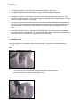
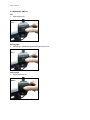
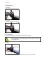
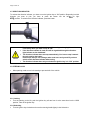
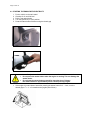
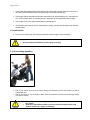
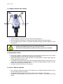
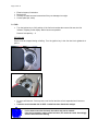
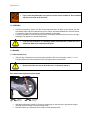
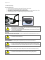
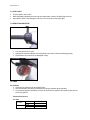
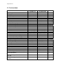
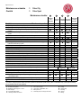
Page 1 from 37
Dear customers!
First of all thank you for buying a vehicle from
our company. Before starting to ride your new
vehicle, we recommend to read this user guide
very careful. It contains a lot of important
information and advices for the correct use. This
user guide is one part of the equipment of the
vehicle and at the sale it must be handed over to
the owner.
We reserve the right to make technical
modifications on the vehicles without changing
the characteristic features of them. We are not
responsible for mistakes in the translation or the
printing of the user guide. If you have any
questions, please contact one of our authorized
dealers.
We wish you a lot of fun and a good start with
your new vehicle.
Page 2 from 37
Index
1. General information
1.1 Prior starting vehicle
1.2 Modifications on the vehicle
1.3 Important code numbers on the vehicle
6. How to stop and park
6.1 Stop
6.2 Parking
6.3 Choice of a suitable parking place
2. Parts location
3. Various parts operation
3.1 Dashboard
3.1.1 Speedometer
3.1.2 Odometer
3.1.3 Oil level indicator
3.1.4 High beam indicator
3.1.5 Direction light indicator
3.1.6 Fuel indicator
3.1.7 Current time function
3.2 Ignition lock
3.3 Starter button
3.4 Headlight switch
3.5 Dimmer switch
3.6 Horn
3.7 Direction indicator
3.8 Steering lock
3.8.1 Locking
3.8.2 Unlocking
3.9 Helmet box
4. Starting engine
4.1 Starting the engine with electricity
4.2 Kickstarter
5. Correct riding operation
5.1 Start up
5.2 Speed adjustment
5.2.1 Acceleration
5.2.2 Deceleration
5.3 Running in instructions
5.4 Correct braking and turning
5.5 Riding when it rains
5.6 Safety through training
7. Inspections before operation
7.1 Fuel
7.2 Steering
7.3 Brakes
7.3.1 Drum brake
7.3.2 Disc brake
7.4 Stop light
7.5 Direction indicator
7.6 Tires
7.7 Shock absorber
7.8 Illumination
7.9 Horn
7.10 Speedometer
7.11 Back mirror
8. Regular maintenance and inspection
8.1 Battery
8.1.1 Removal and assembly of battery
8.2 Fuse
8.3 Bulb replacement
8.3.1 Head light
8.3.2 Direction indicator front and rear
8.3.3 Tail and stop light
8.4 Correct adjustment of low beam
8.5 Inspection of cable rubber parts
9. If engine does not start
10. Safety operation
11. Final thought
12. Technical data
13. Service instructions
Page 3 from 37
1. General ínformation
1.1 PRIOR STARTING VEHICLE
This manual describes matters pertaining to correct operation, safe operation and simple maintenance of
the vehicle you purchased. To ensure more comfortable and safer operation, we recommend to read this
manual carefully prior to operation.
•
•
•
•
•
•
The photographs and pictures shown in this manual may differ from those of actual vehicles due
to changes in vehicle specifications or made modifications.
This vehicle is designed for 2 riders including the operator. If you use the vehicle in an irregular
way, you aren’t eligible for any warranty claim.
Check the vehicle before your first trip.
Keep the vehicle clean and conduct all specified maintenance inspections.
Make sure to stop engine and stay away from fire when refuelling.
Exhaust gas contains harmful substances such as carbon monoxide. Start engine at wellventilated places.
1.2 MODIFICATIONS ON THE VEHICLE
All modifications on the vehicle, as the increase of cylinder capacity, the engine output or speed, change
the characteristic features of the vehicle category. Additional this is prohibited by law and will be
prosecuted. If you ride without any driving license you take a risk that your vehicle will be confiscated and
must be checked and admitted again through the appropriate authority.
Also note, that all modifications regarding the exhaust emission characteristics and noise behaviour
cause the expiry of the driving license.
Furthermore all modifications at illuminiation, license plate, license plate holder, acustic warning devices
or back mirrors are not allowed by law and you haven’t an insurance coverage anymore. Pay attention
that all above mentioned modifications are not covered by warranty and releases the
manufacturer from any liability. Use only genuine parts respectively parts which are recommended
from the manufacturer or authorized dealer. The dealers offer a wide range of accessories which conform
to any technical, functional and aesthetic features of the vehicle and comply to the road traffic regulations.
The fitting of not original accessories, as wind shield, top case may affect your riding safety and
is possibly subject to authorisation. The use of accessories or spare parts not released through the
vehicle manufacturer could cause the expiry of any warranty claim.
Attachment
•
Do not add electrical equipment (radio, illumination) - that will exceed the vehicle’s electrical system
capacity.
Page 4 from 37
1.3 IMPORTANT CODE NUMBERS ON THE VEHICLE
The vehicle has following code numbers:
– vehicle identification number
– engine number
– license plate
Record the vehicle identification number and the engine number along with the vehicle license plate
number and keep them separately from the vehicle.
Any modification of the VIN is not allowed.
Before licence of the vehicle, it is important to compare the VIN on your vehicle with the VIN mentioned in
your vehicle documents.
Vehicle identification number:
The VIN (17-digit) is important for its explicit identification and is needed for registration at the
responsible authority.
It is stamped on the frame as you can see on the picture.
Engine number
The serial number of the engine is stamped on the top of the lh crank case.
Page 5 from 37
2. PARTS LOCATION
OLIVER CITY
Back mirror
Type plate
Anti tampering plate
(under the seat)
Luggage holder
Tail/stop light
Seat lock
VIN
Engine number
Battery
Side stand
Air filter
Kickstarter
Brake lever for
rear wheel
Helmet box
Brake lever for
front wheel
Fuel tank
Direction indicator
Ignition lock
Luggage carrier
Head light
Direction indicator
Exhaust
Oil tank
Main stand
Page 6 from 37
OLIVER SPORT
Back mirror
Type plate
Anti tampering plate
(under seat)
Tail/stop light
Luggage holder
Seat lock
VIN
Engine number
Battery
Air filter
Kickstarter
Side stand
Brake lever for
rear wheel
Fuel tank cap
Brake lever for
front wheel
Helmet box
Direction indicator
Ignition lock
Luggage
carrier
Head light
Direction
indicator
Exhaust
Oil tank
Main stand
Page 7 from 37
3. Various parts operation
3.1 DASHBOARD
Oil indicator
Odometer
Direction light indicator
Fuel level indicator
Speedometer
Time
High beam indicator
3.1.1 Speedometer
• The standard speed indication is km/h.
3.1.2 Odometer
• Total forward distance is indicated in km. The white digits on black background indicate 100- m-units.
3.1.3 Oil level indicator
• If the oil level drops below the MIN-marking in the oil tank, the oil indicator is lighting on the display.
Stop your vehicle immediately and fill up engine oil of specification mentioned in the maintenance
schedule.
• After changing oil and turning the key to “ON”, the oil level indicator has to go out.
Check the function of the oil level indicator by turning the ignition key to the position
between “ON” and “OFF”. In this position the oil level indicator has to light up. Generally
we recommend to check a satisfactory oil level always when you fuel the vehicle.
3.1.4 High beam indicator
• When operating the high beam indicator the symbol for high beam is lighting on the display.
3.1.5 Direction light indicator
• When operating the left or right direction indicator, the relative symbol for the left- or right hand side is
blinking on the display.
3.1.6 Fuel indicator
• It indicates the fuel volume in the fuel tank. If the fuel level reaches the reserve fuel area, the fuel
indicator is lighting on the display. Refuel as soon as possible.
3.1.7 Time
• The time will be indicated in hours and minutes.
Page 8 from 37
• Through pressing the rh mode-button the date will be indicated for about 4 sec.
• Through shortly pressing the lh mode-button the date and the time appear alternately.
• Through pressing the rh mode-button twice, the seconds will be indicated on the display. To reset,
press the lh mode-button twice. Through pressing the rh mode-button the adjustment will be confirmed
and the time will be indicated on the display.
• Through pressing the lh mode-button twice, the month will be indicated. Adjustment through pressing
the rh mode-button, confirmation through pressing the lh mode-button. The display indicates the day –
adjustment through pressing the rh mode-button and confirmation through pressing the lh modebutton.
• The display indicates the hours – adjustment through pressing the rh mode-button and confirmation
through pressing the lh mode-button. The display indicates the minutes – adjustment through pressing
the rh mode-button, confirmation through pressing the lh mode-button.
• Through pressing the rh mode-button the adjusted time now will be indicated on the display.
3.2 IGNITION LOCK
Due to the ignition lock it’s possible to start or stop the engine. The ignition lock is placed below the
operating elements.
Off
•
•
On
The electric circuit of the vehicle is intermitted, the engine cannot be started.
Key can be placed in or taken out of the ignition lock.
Page 9 from 37
•
•
The electric circuit of the vehicle is connected, the engine can be started.
Key cannot be pulled out.
Lock
•
•
The electric circuit of the vehicle is intermitted, the engine cannot be started and the steering is
locked.
Key can be placed in or taken out of the ignition lock.
Never operate the ignition key during travel as it might cause unexpected
accidents. If it is necessary to remove the ignition key, stop the vehicle.
3.3 STARTER BUTTON
•
The starter button is placed next to the throttle grip. Due to pressing the starter button and pulling the
brake lever, the engine can be started (ignition key must placed to “ON” position). (See „starting off
engine“, chapter 4).
Do not press the starter button longer than 4 sec., as the starting motor consumes a
lot of electricity and this discharges the battery.
Page 10 from 37
3.4 HEADLIGHT SWITCH
Off
• Light switched off
Parking light
• Parking light, dashboard light and tail light are turned on.
Driving light
• Driving light turns on.
Page 11 from 37
3.5 DIMMER SWITCH
1. High beam
In this position the high beam is turned on.
2. Low beam
In this position the low beam is turned on.
3. Headlamp flasher
Through keep pressing the high- and low beam switch the high beam is lighting.
•
Use the high beam only in the suburban. Take care to the other road users when
using the high beam!
3.6 HORN
•
The horn sounds if the horn button is pressed and the ignition key is in “ON” position.
h
Page 12 from 37
3.7 DIRECTION INDICATOR
To activate the direction indicator, you have to turn the ignition key to “ON” position. Depending in which
direction you want to ride, you have to press the button into the left
or right
position. To switch off the direction indicator, press the button.
•
•
•
•
You have to use the direction indicator while turning or changing lines and
if necessary when you start or stop to ride.
If the direction indicator is used, this will be signalized through the direction
light indicator on the dashboard.
The direction indicator does not stop automatically. You have to stop it manual
through pushing the button.
Please note, that you can endanger other road users and yourself if you don’t
switch off the direction indicator after turning.
The direction indicator does only work when the ignition key is in “ON” position.
3.8 STEERING LOCK
•
When parking, make sure to lock steering to prevent theft of the vehicle.
3.8.1 Locking
• Turn the steering to the left, push the ignition key soft and turn it at the same time into the LOCK
position. Take off the ignition key.
3.8.2 Unlocking
• Turn the ignition key clockwise and move the steering handle lightly in both directions.
Page 13 from 37
•
•
•
Check to see if the steering has been securely locked by lightly moving the
steering to the left and right hand side.
Make sure to park the vehicle in a safe and suitable location.
Never operate the ignition key during travel as it might cause unexpected
accidents.
3.9 HELMET BOX
•
There is a helmet box under the seat. Do not store any important documents in the helmet box.
Reasons: - potential theft
- water could enter the luggage compartment during washing the vehicle
The helmet box can be opened through turning the ignition key in the helmet box lock. Note, that
the helmet box closes automatically when you shut the cover.
•
•
•
•
•
•
Make sure that the seat is securely locked after closing the seat.
An unlocked seat can affect your riding safety.
The temperature inside the helmet box rises due to the heat from the
engine. Do not place foodstuffs and other articles that can be damaged easily
by heat.
Do not place valuable or fragile goods in the helmet box.
Note that water can enter the helmet box when washing the vehicle.
Do not load stuff more than 3 kg.
4. Starting the engine
•
•
•
The exhaust gas contains poisonous carbon monoxide gas. Never start the
engine in closed areas.
When you start the engine you have always to pull the rear wheel brake. It’s
important for your own safety and to avoid a jerky start of the vehicle.
Do not let run the engine at idle speed – danger of overheating!
Avoid full throttle after cold start!
Page 14 from 37
4.1 STARTING THE ENGINE WITH ELECTRICITY
1.
2.
3.
4.
5.
Put the vehicle on the main stand
Checkup of oil- and fuel level
Pull the rear wheel brake
Turn the ignition key to „ON“ position
Press the starter button without turning the throttle grip
•
•
•
•
Immediately release the starter button as soon as the vehicle has started.
Do not press the starter button when the engine is running. This can damage the
starter motor.
Do not keep the starter button pressed for more than 4 sec. Release
the starter button for approximately 30 sec. before pressing it again.
If the engine is hot and doesn’t start after pressing the starter button for 3 – 4 sec., turn the
throttle grip to 1/8 ~ ¼ of a rotation and try again (after 30 sec.).
Page 15 from 37
•
It is possible that starting will be more difficult if the vehicle has not been used for a long time. In
this case, push the starter button a few times without turning the throttle grip.
•
If the engine did not start after pushing the starter button for approximately 4 sec., wait about 30
sec. before trying it again. This waiting period is important for the regeneration of the battery.
•
If the engine is cold, the engine should warm up at idle speed.
•
If the electric start does not work or if the battery is empty, you can start the engine also by using
the kickstarter.
4.2 KICKSTARTER
•
Don’t turn the throttle grip, pass through kickstarter pedal strongly to start the engine.
•
Do not operate the kickstarter, if the engine is running.
5. Correct riding operation
•
•
Roll off the vehicle from the main stand. During this operation pull the rear brake to avoid an
unexpected start.
Get on the vehicle. If you are ready to start, loose the brake lever and turn the throttle grip slowly
to move the vehicle.
•
•
Do not turn on the throttle grip quickly, to prevent an unexpected break out of
the vehicle.
Note that it should be avoided to sit on the vehicle during the main- side
stand is clicked off – danger of breakage.
Page 16 from 37
5.1 START UP
•
Pay attention to the traffic around you before start riding and use the direction indicators if necessary.
5.2 SPEED ADJUSTMENT
The speed is always dependent on the position of the throttle grip.
5.2.1 Acceleration
• The speed of the vehicle increases due to turning the throttle grip against the driving direction.
When climbing a hill, the throttle grip needs to be turned stronger to give the vehicle more power.
5.2.2 Deceleration
• The speed decreases due to turning the throttle grip in driving direction.
•
A quick rotating of the throttle grip will cause the vehicle to move forward
suddenly!
5.3 RUNNING-IN INSTRUCTIONS
An initial break-in phase of the engine ensures optimum service life and performance of the engine.
Therefore note following proposals:
•
•
•
•
•
Maximum engine speed during the first 1000 km should not exceed 40 km/h, also avoid
continuous full load.
Avoid sudden acceleration, to increase the durability of the engine.
Do not operate the engine at high revolutions without loading (for example at full throttle on the
main stand)
New tires have a smooth surface. It is necessary to roughen the tires through careful running-in.
In this way the contact surface of the tires will receive their full adhesion.
Additional it’s important to break-in new brake pads. Pay attention that new brake pads do not
have their full friction force during the first 500 km. The braking effort can be improved due to
pulling the brake levers stronger. Avoid any hard stops at this period.
Safety regulations during riding
•
•
•
•
•
Always pay attention to have enough safety distance to other road users
Ride defensive
Do not hinder other road users
Do not ride on side walks
Always ride in a way to be able to stop your vehicle immediately
Page 17 from 37
5.4 CORRECT BRAKING AND TURNING
Brake lever for
rear wheel
•
•
•
Brake lever for
front wheel
Sudden braking or turning can cause the vehicle to slide and tip over.
After returning the throttle grip to its original position, apply front and rear brake together.
The most effective way to brake, is to operate the brakes first lightly and then change to a more
firm squeeze.
•
•
•
You have to pull front- and rear brake always together.
Sudden and hard brake maneuver can cause an accident!
Note that the braking distance extends a lot when you just use one brake!
5.5 RIDING WHEN IT RAINS
•
•
•
•
More braking distance is needed when riding on wet roads. Reduce speed and be sure to initiate
the braking operation sooner than when riding at normal conditions.
While riding downhill, turn the throttle grip back to its initial position to reduce speed, apply the
brakes and ride slowly down the hill.
It’s possible that the brakes temporarily loose their proper braking effort after a ride in the rain. To
ensure that the brakes are operating properly, slow down and lightly apply the brakes to rid the
brakes of any excess water and to dry them.
If possible, avoid to ride at snow or on icy roads.
5.6 SAFETY THROUGH TRAINING
•
–
–
Get a feeling for dangerous situations. This means, think of potential hazards and don’t trust in
the correct riding of other road users.
It’s important to ride through curves rhythmical without any hard stops or full throttle.
Reduce the speed accurately when you ride into a curve – safety is more important than high
speed!
Page 18 from 37
–
•
•
–
You have to look ahead along the inner side of the planed lane, so that you can see early enough
the exit of the corner.
Consider the reaction time when you brake.
Train with and without passenger
the reaction of the brake on different road lengths. Find out carefully when the tires block.
6. HOW TO STOP AND PARK
6.1 STOP
•
•
Turn on the direction indicator timely and take care of vehicles behind you.
Return the throttle grip back in it’s original position and apply the front- and rear brake together.
The stop light will lighten and alert vehicles behind of you that you are stopping.
6.2 PARKING
•
After stopping the vehicle, switch off the direction indicator and turn the ignition key to “OFF” position,
to stop the engine.
•
Never operate the ignition key during riding the vehicle, as it might cause
an accident.
6.3 CHOICE OF A SUITABLE PARKING PLACE
•
•
•
•
Be sure to park in an area that is free of traffic. Pay attention that you park your vehicle on a firm,
level ground.
Put the vehicle on its main- or side stand.
To park the vehicle, hold the steering with the left hand and click down the main stand with the right
foot.
To prevent stealing, lock the steering while parking and pull out the ignition key.
•
•
Always park your vehicle in a safe area that is free of traffic.
Pay attention to the hot engine and exhaust system!
7. Self inspections before operation
Check the vehicle and have regular maintenance inspections for increased safety and prevention of
accidents.
If you find any malfunction during inspection or anything seems to be abnormal, contact one of our
authorized dealers for inspection and repair.
Prior operating the vehicle, always perform following checkups:
Checkup of the security relevant components:
• Fuel level
• Tires
• Brakes, brake fluid
• Engine oil level
Page 19 from 37
•
•
•
•
Electrical system, illumination
Back mirrors
Checkup of brake hose and connections if they are damaged or untight.
License plate (dirt, crack)
7.1 FUEL
•
Turn the ignition key to „ON“ position. If the fuel level reaches the reserve fuel area, the fuel
indicator is lighting on the display. Refuel as soon as possible.
Reserve fuel capacity: ~ 1l
REFUELLING
Engine must be stopped during refuelling. Turn the ignition key in the fuel tank lock rightwards to
open it.
•
•
Do not overfill the tank. Fuel may leak out of the fuel tank due to fuel expands when it becomes
warm.
It must be used unleaded fuel 91 ROZ – leaded fuel does disturb the catalyst.
•
•
If oil or water enters the fuel tank, the vehicle may not be started!
If the fuel is leaked by rupture of the fuel hose, fire can be the result. Accordingly
check if the fuel hose is leaking.
Page 20 from 37
•
Fuel is extremely flammable and explosive under certain conditions. Do not handle
with fire in the near of the fuel tank.
7.2 STEERING
•
•
Check the steering by moving it to the left and right hand side. Sit down on the vehicle, pull the
front wheel brake and push respectively pull the vehicle forward and backward. At these actions
no clearance of the front suspension must be hearable or noticeable.
It must be possible to move the steering evenly and without resistance from the left to the right
hand side. Pay attention to any abnormal noise.
•
If you feel any resistance or something seems to be abnormal, contact one of our
authorized dealers for inspection and repair.
7.3 BRAKES
7.3.1 Drum brake (rear)
•
The free play of brake lever has to be properly adjusted. The correct free play is about 1 – 2 cm.
Free play means the distance between loose and tight position of brake lever.
•
Always check the free play at the brake lever. If necessary adjust it.
Rear wheel brake adjustment (drum brake)
reduces
free play
•
•
increases
free play
After brake adjustment, match the concavity of adjusting nut with axle pin to prevent the danger
resulting from the change of free play during riding.
Ride the vehicle on a short distance to make sure the retarding effort.
Page 21 from 37
7.3.2 Disc brake (front)
Check-up of brake fluid
• You have to turn the steering thus the brake fluid is level in the reservoir.
• The brake fluid level must not drop below the “MIN” marking
• If the bake fluid is significantly lower than the specified level, check the brake pads for wear. lf the
brake pads are ok, also the braking system must be inspected.
• If the brake pads are worn out, let them change through an authorized dealer.
Inspection glass
•
•
If brake fluid level is exceedingly low, it can be a sign for a defect of the
brake system. A leak in the brake system can lead to reduce the braking efficiency
and possible loss of retarding effort.
To ensure the operating safety of the brake system, all works have to be done by
one of our authorized dealer!
Wet brakes
After washing the vehicle or during riding in the rain, the retarding effort could be delayed due to wet or in
winter iced-up brake discs and brake pads.
•
The brakes must be braked dry!
Salt on the brakes
It is also possible that the retarding effort is delayed when you ride on roads covered with salt.
•
•
The salt on the brake discs and brake pads must be grinded off during braking!
Pay attention that brake discs and brake pads also must be free of oil and grease!
Dirty brakes
At trips on dirty roads, the retarding effort could be delayed as the brake discs and brake pads are dirty.
•
The brakes must be braked clean! Increased wear through dirty brakes!
Page 22 from 37
7.4 STOP LIGHT
•
•
•
Turn the ignition key to „ON“.
While separately operating the front and rear wheel brake, check if the brake light turns on.
Also check if there is any damage to the lens or if there is dirt on the brake light.
7.5 DIRECTION INDICATOR
•
•
•
Turn the ignition key to „ON“.
Operate the direction indicator for both directions and check if they are flashing properly.
Check also if any of the lens are damaged or dirty.
7.6 TIRES
Air pressure
• Check the tire pressure just at cooled off tires.
• We recommend to check the tire pressure by using a pressure gauge regularly.
• If no pressure gauge is available, you have to check the tire pressure by examining how the tire
sits on the ground.
Correct tire pressure
12“ tires
Front
Rear
Front
Air pressure
Rear
Tire size
120/70-12
130/70-12
1,9 bar
2,0 bar
Page 23 from 37
•
•
•
•
Not correct tire pressure causes abnormal wear and an insecure vehicle
handling!
Check tire tread and sides for nails, rocks etc., that might have become wedged in the tire.
Check tire tread and sides for cracks and damage.
Check-up of tread depth – recommendation 2 mm at all areas of the tire (pay attention to the
demanded minimum tread depth).
•
•
•
If there is any crack or wear exceeding the limit, replace the tire at once!
After replacing the tires, check the reaction of the brakes at a safe area without
traffic!
The main reason of going crack, unstable handling and abnormal abrasion is
a wrong tire pressure (too high or too low).
7.7 SHOCK ABSORBER
•
•
•
Apply the front wheel brake and swing the vehicle up and down while adding your weight on the
steering, to check if the front shock absorber works well.
To check the function of the rear suspension strut, you have to move the vehicle up and down
with your weight in the back area.
Check the tightness of the shock absorber.
•
If the shock absorber or the suspension strut does not work correctly or if you
found out a leakiness, you have to contact an authorized dealer immediately.
7.8 ILLUMINATION
•
•
•
•
Turn the ignition key to „ON“.
Operate the headlight switch to see if the light turns on.
Check all lights if they are dirty or damaged.
Check the correct adjustment of the headlight. The light of the low beam must shine 1% in direction to
the road surface. If you are not sure if your headlight has the correct adjustment, contact one of our
authorized dealers for check-up!
7.9 HORN
•
Turn the ignition key to „ON“ and press the horn switch button to check if the horn sounds.
Page 24 from 37
7.10 SPEEDOMETER
•
•
•
•
Check the speedometer spindle for damages regularly.
Ensure sufficient lubrication of speedometer gear.
Do not wash the vehicle with high pressure to avoid that what can enter.
Check the correct function of the speedometer when you start to ride.
7.11 BACK MIRROR
•
Sit down on the vehicle and check the correct adjustment of the back mirrors as well if they are dirty
or damaged.
8. Regular maintenance and inspection
For safe and smooth riding regularly maintenance and inspections are absolutely necessary. Our
authorized dealers provide after-sales service, maintenance and repair for you. Consider, that in the
owner manual you’ll just find a few points of maintenance.
Also the attached emergency tool is suitable for small repair works.
To be able to make a proper inspection it’s important to have a special training as well you need suitable
tools. Additional all screws must be checked for the correct assembling torque. Therefore we
recommend to do repairs by yourself just in emergency cases but anyway accordingly contact
your authorized dealer for check-up.
Permanent high speed operation, or operation in unusual wet or dusty conditions, will require more
frequent service than specified in the maintenance schedule.
SAFETEY INSTRUCTIONS:
•
•
•
Make sure that the vehicle stands on smooth, level ground on it’s main stand!
The engine must be off and the ignition key must be pulled out at any repair
works.
Pay attention to the hot exhaust system after stopping the vehicle!
8.1 BATTERY
Maintenance-free battery (M/F)
This vehicle is equipped with a maintenace-free battery. It’s not necessary to check the battery electrolyte
level or add distilled water – do never remove the battery cap!
8.1.1. Removal and assembly of battery
1.
2.
3.
4.
The battery is placed in the recess of the floor panel.
Remove the cap of the floor panel through loosen the screws.
Make sure that the ignition is switched off, when you connect or disconnect the battery cables.
Disconnect the negative (-) terminal lead from the battery first, then disconnect the positive (+)
terminal lead. Consider the correct order to avoid a short circuit!
5. If the battery terminals are polluted or in rust, separate battery and clean them, if necessary
lubricate them with special grease.
•
•
Stay away with all flammable materials during handling with battery. Batteries
give off explosive gases.
Make sure that the terminals do not contact other adjacent parts. Contact with
other parts may cause a malfunction of electrical system, fire or an electric
shock!
Page 25 from 37
•
•
Wear safety goggles and protective gloves always during works at the battery!
The charging of the battery has to be done exclusively from an authorized dealer!
•
When not using the vehicle for a long time, the battery discharges and must
be full charged at the next trip with the vehicle (authorized dealer).
When not using the vehicle for a long time, we recommend to take off the
battery and to store it in full charged condition on a well ventilated place.
Otherwise it could result in a durable damage of the battery.
Proper charging and storage increases the durability of the battery.
•
•
8.2 FUSE
If the electrical equipment doesn’t work after turning the ignition key to „ON“ position, check the
fuse.
•
•
•
The fuse is placed near the battery.
Remove the cover of fuse box and take out the fuse.
Check-up of fuse, if necessary replace it. Pay attention that the fuse fits proper as well that the
contacts are clean and dry.
•
•
•
•
•
•
Always use the recommended fuse. Using different fuses may cause cable fire!
When replacing any of the electrical parts, be sure to replace them with genuine
parts. Using different parts can lead to the fuse burning out or damage to the
battery.
If a short circuit was the reason for a defect fuse, you have to consult an
authorized dealer.
Always switch off the ignition before you replace the fuse! Defect fuses must be
exchanged. No repair of defective fuses – fire hazard!
Carry along reserve fuses!
Do not wash your vehicle with high pressure water.
8.3 BULB REPLACEMENT
•
•
•
Be sure to turn the ignition to „OFF“ position when replacing bulbs.
Generally you have to be careful at handling with electrical components and
cables.
Do not touch the bulbs with your fingers as they must absolutely be free of
grease! Wear clean gloves while replacing bulbs.
Pay attention to proper electric contacts!
Page 26 from 37
The vehicle is equipped each with a lamp for low- and high beam, parking light and additional for stop
light and tail light.
8.3.1 Head light
1. Turn the ignition key to „OFF“ position.
2. Remove the front cover by using a suitable screw driver. Loosen the connector.
3. Take out the bulb and replace it.
ATTENTION – touch bulb exclusively on the socket – it must be free of grease!
4. Assembling in reverse order.
•
•
At the removal of plastic parts, pay attention that they won’t be scratched.
Additional you have to attend to connection clamps so that they won’t be
damaged. In case of doubt contact one of our authorized dealer.
Pay attention to the correct fixing of the bulb to ensure its function. The plastic
ring must snap in and the bulb must be fixed in the correct position.
8.3.2 Front and rear direction indicator
1. Turn the ignition key to „OFF“ position.
2. Remove the two indicator lens carefully (transparent and orange) by using a suitable screwdriver.
3. Through lightly pulling, the bulb can be removed.
4. Assembling in reverse order.
8.3.3 Tail- stop light
1. Remove the taillight housing carefully.
2. Press and turn to the left to take out the bulb.
3. Assembling in opposite succession.
8.4 CORRECT ADJUSTMENT OF LOW BEAM
The correct adjustment of the low beam is important for your own safety as well for the safety of all other
road users. When buying the vehicle, the head light is already correct adjusted. To check or adjust the
head light you have to consult an authorized dealer. If the normal load conditions of the vehicle change,
the head light adjustment has to be adapted.
8.5 INSPECTION OF CABLE RUBBER PARTS
For protection of the inner cable there are assembled rubber bushings on the cables. Make sure that the
rubber bushing is placed firmly around the cable. When washing the vehicle, do not directly spray water
on the rubber part. Use a dry cloth to clean this area.
Page 27 from 37
•
•
According to the maintenance schedule the rubber bushings must be checked
and lubricated regularly!
Avoid access water as it could cause corrosion and water freeze in the winter.
9. If engine does not start . . .
•
•
•
•
•
Check the fuel level.
Try to start the vehicle by operating the kickstarter.
Check the spark plug.
Battery discharged?
If the vehicle nevertheless couldn’t be started consult an authorized dealer for inspection.
10. Safety operation
•
•
We recommend to consult your workshop frequently allthough your vehicle is may out of
warranty. This is the best way to ensure that your vehcile is well maintained and everything is
working well.
Your dealer knows your vehicle well and is able to find out little mistakes on time whereby big
difficulties could be avoided in advance. In this way you can save time and money.
11. Final thought
That can you do for your vehicle:
•
•
•
•
•
Regularly maintenance and check up of all functions before start riding.
If possible avoid a direct and long-term insolation of the vehicle (damages of the varnish, head
light).
Maintenance of your vehicle through specialized staff of your dealer.
Use only original accessories. It complies to all safety regulations as well it is adjusted especially
for your vehicle.
Do not fit non licensed accessories. You take the risk to loose insurance coverage and your
driving license.
Page 28 from 37
12. Technical data
Type of engine
Cooling system
Lubrication system
Bore / Stroke
Cylinder capacity
Compression ratio
Nominal power
Nominal torque
Fuel tank max. capacity
Sort of fuel
Stroke of front suspension
Stroke of rear suspension
Brake front
Brake rear
Rim size front
Rim size rear
Tire size front
Tire size rear
Transmission primary ratio (R1)
Transmission secundary ratio (R2)
Transmission final drive ratio (R3)
Capacity of battery
Nominal output of generator
Power input headlamp
Ignition system
Length
Width
Height
Height of riders seat
Wheelbase
Mass in running order
Max. technically permissable mass declared
by the manufacturer
Max. technically permissable mass of
front axle
Max. technically permissable mass of
rear axle
OLIVER CITY
OLIVER SPORT
1 cyl. 2 stroke
Air
Separate lubrication
40,0/39,2
49,2
8,4:1
2,4 / 5900
4,0 / 5400
5,2
min. 91
75
45
Disc
Drum
E12 x 3,50 DOT
E12 x 3,50 DOT
120 / 70 – 12 51J
130 / 70 – 12 56J
1:1
2,65 – 1,03
13,54
12 / 3
89,6 / 5000
35 / 35 (S2)
CDI
1839
664
1131
760
1260
91,5
240
1 cyl. 2 stroke
Air
Separate lubrication
40,0/39,2
49,2
8,4:1
2,4 / 5900
4,0 / 5400
5,2
min. 91
75
45
Disc
Drum
E12 x 3,50 DOT
E12 x 3,50 DOT
120 / 70 – 12 51J
130 / 70 – 12 56J
1:1
2,65 – 1,03
13,54
12 / 3
89,6 / 5000
35 / 35 (HS1)
CDI
1839
664
1131
760
1260
91,5
240
100
100
[kg]
140
140
[kg]
[mm]
[cm³]
[KW/min-1]
[Nm/min-1]
[l]
[ROZ]
[mm]
[mm]
[V/AH]
[W/min-1]
[W]
[mm]
[mm]
[mm]
[mm]
[mm]
[kg]
[kg]
Page 29 from 37
13. Service instructions
The service- and inspection instructions include the warranty rules and the maintenance schedule for
your vehicle.
Make sure that the service- and inspection book will be filled in by your dealer when you take over the
vehicle. The two delivery cards must be sent from the dealer to our company immediately after handing
over.
For any demand on warranty you have to provide the valid service book to your dealer. Additional all
repairs must be confirmed in your service book with date, stamp and signature.
Page 30 from 37
AFTER-SALES SERVICE CARD
Attention! DO NOT TEAR OFF
Vehicle owner: (Please write in capital letters)
Surname: ................................................... First name: ......................................
Street: ..................................................................................................................
Place: ...................................................................................................................
Age: ..........................years
.......................................................... ................................. ..............................
Stamp/signature dealer
date
Signature final customer
HANDING OVER CARD
To tear off and send from the dealer to:
Vehicle owner: (Please write in capital letters)
Surname: ................................................... First name: ......................................
Street: ..................................................................................................................
Place: ...................................................................................................................
Age: ..........................years
.......................................................... ................................. ..............................
Stamp/signature dealer
date
Signature final customer
Page 31 from 37
HANDING OVER CARD
To tear off and send from the dealer to:
Check up of external impression:
Check up of fluid lever:
•
•
•
•
•
O.K
Check up of fixing screws:
O.K.
Electrical equipment:
Test riding:
• Main switch
• Headlight (high/low beam)
• Adjustment of the headlight according to
the rules
• Tail light, stop light
• Front and rear stop lights switch
• Flasher lights and indicator lights
• Light for dashboard
• Dashboard: fuel lever- and temperature gauge
• Indicator lights on the dashboard
• Horn
• Starter
O.K.
Further checks:
•
•
•
•
•
•
•
•
function of the clutch
function 2-stroke engine
function 4-stroke engine
move of levers
move of pedals
adjustment of the oil pump
check of move of the throttle grip
check of the vehicle documents
Battery
Brake fluid lever
Cooling fluid lever
Engine oil lever
Transmission oil lever
O.K.
•
•
•
•
•
•
•
Starting at cold engine
Function of the instruments
Reaction when use throttle grip
Stability at speeding up and decelerate
Function of front- and rear brake
Function of front- and rear shock absorber
Any abnormal noise
O.K.
Check up after riding test
•
•
•
•
•
•
•
•
•
•
•
Starting at warm engine
Function of the starter
Regularity of the idle speed
Eventually loss of fluids
O.K.
check of frame- and engine number
emergency tool set
fixing license plate number
check of locks
check of tire pressure
fixing of back mirror and other fittings
other things
O.K.
The dealer confirms herewith the correct done of repairing works according to the maintanance schedule
The customer confirms herewith the taking over of the vehicle including all vehicle documents
(license, user guide and servicebook)
....................................................
stamp/signature dealer
........................................
date
.............................................................
signature final costumer
Page 32 from 37
REGULAR CARD
ATTENTION! For the customer file of the dealer
Vehicle owner: (Please write in capital letters)
Surname: ................................................... First name: ......................................
Street: ..................................................................................................................
Place: ...................................................................................................................
Age: ..........................years
.......................................................... ................................. ..............................
Stamp/signature dealer
date
Signature final customer
CHANGE OF VEHICLE OWNER
To tear off and send from the dealer to:
Vehicle owner: (Please write in capital letters)
Surname: ................................................... First name: ......................................
Street: ..................................................................................................................
Place: ...................................................................................................................
Age: ..........................years
.......................................................... ................................. ..............................
Stamp/signature dealer
date
Signature final customer
Page 33 from 37
Confirmation of the finished works:
Handing over inspection
1. Inspection at 1000 km
Mileage:________________
Mileage: _______________
________________________________ _______________________________
data, stamp, signature
data, stamp, signature
2. Inspection at 4000 km
3. Inspection at 8000 km
(latest after 12 months)
(latest after 24 months)
Mileage: _______________
Mileage: _______________
________________________________ ________________________________
data, stamp, signature
data, stamp, signature
4. Inspection at 12000 km
5. Inspection at 16000 km
(latest after 36 months)
(latest after 48 months)
Mileage: _________________
Mileage: ________________
________________________________ ________________________________
data, stamp, signature
data, stamp, signature
6. Inspection at 20000 km
7. Inspection at 24000 km
(latest at 60 months)
(latest at 72 months)
Mileage: __________________
Mileage: _________________
________________________________ ________________________________
data, stamp, signature
data, stamp, signature
8. Inspection at 28000 km
9. Inspection at 32000 km
(latest after 84 months)
(latest after 96 months)
Mileage: _________________
Mileage: _________________
________________________________ ________________________________
data, stamp, signature
data, stamp, signature
10. Inspection at 36000 km
11. Inspection at 40000 km
(latest after 108 months)
(latest after 120 months)
Mileage: __________________
Mileage: __________________
________________________________ ________________________________
data, stamp, signature
data, stamp, signature
Page 34 from 37
Oliver City
Oliver Sport
Maintenance schedule
Checklist
Maintenance schedule:
Handing
over
inspection
Checklist:
Time for each operation:
Checking oil level, if necessary fill up
Checking and cleaning the spark plug , if necessary replacing
Checking steering bearing, if necessary adjusting and lubricating (at least every
2 years)
Front fork assy: checking function and consistency; changing the oil at least every
2 years
Rear shock absorber: checking function and consistency
Wheel bearing: Lash and possible damages
Speedometer drive gear, speedometer cable: possible damages; lubricating
Brake lines: possible damages
Braking system: possible damages, consistency, brake fluid level; changing the
brake fluid at least every 2 years*
Brake pad wear; cleaning rear and front brake
Drum brake: control shaft
Function of braking system
Wheels: possible damages; run-out, wheels imbalance, profile depth
Wheels: air pressure
Engine: cylinder head, piston, piston rings, transfer passage – checking the wear
Transmission: consistency; changing of transmission oil at least every 8000 km
V-belt: wear and cracking
Regulator rollers variomatic: checking the wear
Carburator: carburator adjusting
Air filter
Fresh oil pump: venting and checking function
Fuel line/filter: possible damages; consistency
Battery: maintenance free – please use only original battery fluid
Battery terminal
Control cables: routing of cables, adjustment, possible damages
Bearing positions of all movable parts
All screws/nuts of steering assembly, braking system, engine mount and chassis
– assembling torques
Electric system: horn, lighting, adjustment headlight beam setting
Test drive and end control of function and safety in traffic
----
1000 km 12 months 24 months
service or 4000km or 8000km
1,1
1,3
1,9 / 2,9
---A
B
▲(r )
C
( )
D
▲r
▲
▲
▲
Specification
/ working
materials
E
DOT 4
L
( )
r
C
▲
▲
▲
▲
F
r
G
r
r
r
r
r ( )
Special
batterie fluid
MF Type –
maintenance free
▲
▲
▲
▲
▲
r
▲
▲
E
r
▲
▲
H
C/E
C/E
K
* You have to change the piston seal of main brake cylinder and wheel brake cylinder every 2 years – brake hoses every 4 years (time for working
are not included in time for each operation)
A:
B:
C:
D:
E:
Two stroke oil full synthetic
NGK BR7ES, spark plug gap 0,7 - 0,8 mm
Roller bearing oil
Fork oil SAE 5W20 Synthetic
Lubricating oil without resin and acid
F:
G:
H:
K:
Front 1,9 bar, rear 2bar
Transmission oil SAE 80W90, 100 cc
Battery terminal oil
Assembling torques according technical data
: checking
adjusting, filling
: lubricating
: replacing
r: cleaning
▲:
Page 35 from 37
WARRANTY POLICY
(valid from 03.01.2005)
We guarantee for the quality of vehicles and spare parts sold from us (for a period of 24 months) according to legal
requirements.
REQUIREMENTS:
For any demand on warranty you have to meet following requirements
•
The delivery cards must be signed from dealer and customer and have to be sent in due time.
•
The compliance with the prescribed service intervals according to the maintenance schedule and the
presentation of the correct filled in service-book.
The service and repairing works have to be done only by your dealer (authorized dealer).
•
The exclusive use of original spare parts – for spare parts which aren’t released from the manufacturer we
neither give any warranty for the spare parts nor for eventually caused consequential damages.
Not included in the warranty are
the following mentioned wearing parts and wearing materials, when they come up to their ordinary expectations respectively
when you cause more wearing due to wrong handling or wrong behaviour:
•
•
•
•
•
•
•
•
•
•
spark plugs
filter
drive belts or drive pads
brake- or clutch belts
lamps, fuses, batteries
tires, tubes
rubber parts, cables
speedometer cables
variator rollers
service fluids and lubricant
Additional not included in the warranty are:
•
•
•
•
•
•
•
•
Any damages on the surfaces of parts caused by incorrect and insufficient maintenance or wrong storage
respectively transport of the vehicle.
Damages because of using the vehicle for racing or motor sport.
Damages because of overloading the vehicle.
Damages caused by modifications (for example the manipulation of the engine power) on the vehicle.
All regularly and irregularly service and maintenance works.
Damages caused by any acts of god.
Damages caused by any outer circumstances.
Signs of old age (for example fade of coloured or metal coated surfaces).
Warranty:
We issue a 24-months guarantee on the stainless steel exhaust against rust.
We have the right, to improve everytime a product with technical modifications respectively to bring them up to a
higher technical level and to use the changed products or parts according to the warranty.
Page 36 from 37
TIPS FOR MAINTENANCE
It is important to check your vehicle always before starting. This is first important for your own safety. Additional it is easier to
make any repairing works at home then anywhere else.
Appearance and market value respectively wearing of the vehicle are mainly dependent on regular and careful maintenance.
Especially in the winter (bad influence of thawing salt) an often cleaning is very important.
Taking away of thawing salt
•
After riding the vehicle clean it with cold water immediately
•
Do not use warm water – it increases the influence of thawing salt
•
Dry the vehicle careful
•
Cleaned and dried plastic parts polishing with a special wax
ATTENTION: Do not use any vehicle- or cold cleaner for plastic parts.
Vehicle- and cold cleaner contain solvent which takes elastomer away from the plastic - the material gets brittle.
Avoid the use of high pressure- and stream jet cleaner because it’s possible that they damage the varnish.
For the cleaning of engine, wheels and exhaust you could use commercial cleaner, after this clean them with clear water.
Please pay attention that cleaner which are polluting to the environment have no contact with the ground.
Furthermore it is important that you don’t turn the jet of water directly to bearings because it is possible that they could get
rusty by the moisture.
Not varnished aluminium parts like engine- and transmission housing should be put on with transparent chromic fluid to
protect them against corrosion in the winter.
Parts without surface treatment will cleaned and protected with a chrome polish.
The seat, instrument covers, flasher lights, tail light should only cleaned with washing-up liquids. Don’t use any solvent!
Heavy dirt you have to clean with a soapsud and a lot of clear water.
If you plan to storage your vehicle for a long time your dealer will give you important tips.
Longer non-use of the vehicle
If storage will last more than one month, we recommend for proper performance after storage as well for long term
maintenance of value:
•
•
•
•
•
•
•
Wash and dry your vehicle carefully. Wax all painted surfaces.
Refuel and fill in additional 1% corrosion protection. Drain the carburetor.
Screw off the spark plug and put some oil into the spark plug hole. Now operate the kickstarter several times to
spread the oil evenly.
If the vehicle will not used for more than 1 month it is important to drain fuel from the carburetor because otherwise
the fuel resinates and engine possibly could not be started.
Remove the battery. Store in an area protected from freezing temperatures and direct sunlight. Check the battery
once a month and charge if necessary.
All metal parts must be sprayed with corrosion inhibitor.
Cover the vehicle (don’t use plastic or other coated materials) and store in an unheated area, free of dampness with
a minimum of daily temperature variation. Do not store the vehicle in direct sunlight.
Page 37 from 37
DRIVING TIPS
Important tips for correct driving and to avoid too early wearing on your vehicle as following:
•
•
•
•
•
•
•
•
•
•
•
•
•
Pay attention to the run in tips
Avoid too much cold starts
Avoid a heavy duty of the vehicle during the engine hasn’t reached running temperature
Avoid continuous full power of engine
Too high speed at low gears (just for vehicles with gear)
Permanent riding on dusty and dirty streets
Permanent riding when it is raining
Not keeping the maintenance intervals
Any changes on your vehicle (especially increases of the power)
Permanent driving with an overloaded vehicle
Sudden brake maneuvers
Permanent riding on gravel streets (Driving on difficult grounds, kerbs or through potholes)
Riding in the winter without careful cleaning (thawing salt!)