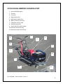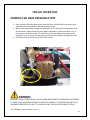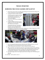
1
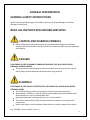
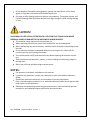
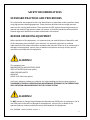
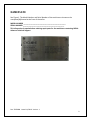
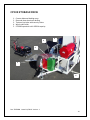
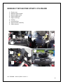
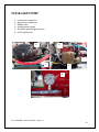
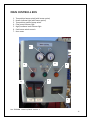
TR5500 USE AND CARE/SERVICE
High-pressure surface cleaning and water
recovery/recycling system
For use with the CY200 walk behind surface
cleaner/recovery system
Doc: TR5500M Issued: 11/2010 Version: 1
1
Table of Contents
GENERAL INFORMATION……………………………………………………………………………………………………….3
SAFETY RECOMMENDATIONS………………………………………………………………………………………………..5
INTRODUCTION……………………………………………………………………………………………………………………..8
NAMEPLATE…………………………………………………………………………………………………………………………..9
KNOW YOUR MACHINE………………………………………………………………………………………………………..10
CHASIS……………………………………………………………………………………………………………………..12
FUEL TANKS………………………………………………………………………………………………………………13
STORAGE DECK…………………………………………………………………………………………………………14
KOHLER ENGINE……………………………………………………………………………………………………….15
GIANT PUMP…………………………………………………………………………………………………………….16
CONTROL BOX………………………………………………………………………………………………………….17
FILTER PUMP…………………………………………………………………………………………………………….18
HEATER…………………………………………………………………………………………………………………….19
UNLOADER VALVE…………………………………………………………………………………………………….20
HEATER COIL…………………………………………………………………………………………………………....21
BATTERY…………………………………………………………………………………………………………………..22
FILTER ASSEMBLY……………………………………………………………………………………………………..23
PRESSURE WAND……………………………………………………………………………………………………..24
HOSING…………………………………………………………………………………………………………………….25
WATER TANK……………………………………………………………………………………………………………26
CY200 WALK BEHIND UNIT……………………………………………………………………………………….27
TR5500 OPERATION……………………………………………………………………………………………………………..28
CLEANING PROCEDURE………………………………………………………………………………………………………..33
MAINTENANCE…………………………………………………………………………………………………………………….37
JACKING POINTS……………………………………………………………………………………………………….38
CHART………………………………………………………………………………………………………………………39
SPRAY TIPS……………………………………………………………………………………………………………….40
LUBRICATION POINTS……………………………………………………………………………………………….41
ELECTRICAL SCHEMATIC……………………………………………………………………………………………………….42
WATER FLOW CHART……………………………………………………………………………………………………………43
Doc: TR5500M Issued: 11/2010 Version: 1
2
GENERAL INFORMATION
GENERAL SAFETY INSTRUCTIONS
Specific Cautions and Warnings are included to warn you of potential danger of machine
damage or bodily harm.
READ ALL INSTRUCTIONS BEFORE SERVICING
CAUTION AND WARNING SYMBOLS
Nilfisk-Advance uses the symbols below to signal potentially dangerous conditions.
Always read this information carefully and take the necessary steps to protect personnel
and property.
DANGER!
THIS SYMBOL IS USED TO WARN OF IMMEDIATE HAZARDS THAT WILL CAUSE SEVERE
PERSONAL INJURY OR DEATH.
This machine emits exhaust gases (carbon monoxide) that can cause serious injury or
death; always provide adequate ventilation when using machine.
WARNING!
THIS SYMBOL IS USED TO CALL ATTENTION TO A SITUATION THAT COULD CAUSE SEVERE
PERSONAL INJURY.
This machine shall be used only by properly trained and authorized persons.
When towing a TR5500 on ramps or inclines, avoid sudden stops when loaded. Avoid
abrupt sharp turns. Use low speeds down hills.
High speed operation is designed only for use on level surfaces.
Turn the key switch off (O) and disconnect the batteries before servicing electrical
components.
Never work under a machine without safety blocks or stands to support the machine.
Doc: TR5500M Issued: 11/2010 Version: 1
3
Do not dispense flammable cleaning agents, operate the machine on or near these
agents, or operate in areas where flammable liquids exist.
Ear plugs or other hearing protection devices are mandatory. The engines, pumps, and
Cyclone Cleaning Head all produce decibel levels high enough to cause hearing damage
or loss.
CAUTION!
THIS SYMBOL IS USED TO CALL ATTENTION TO A SITUTION THAT COULD CAUSE MINOR
PERSONAL INJURY OR DAMAGE TO THE MACHINE OR OTHER PROPERTY.
This machine is only approved for hard surface use.
When operating this machine, ensure that third parties are not endangered.
Before performing any service function, carefully read all instructions pertaining to that
function.
Do not leave the machine unattended without first turning the key switch off (O),
removing the key and chocking the wheels.
Turn the key switch off (O) and remove the key before opening the electrical control
box.
Take precautions to prevent hair, jewelry, or loose clothing from becoming caught in
moving parts.
Before use, all hoses and drain plugs must be secure.
NOTES:
Pay attention to all decals and labels on this machine.
If you have any questions, contact your supervisor or your local Advance Industrial
Dealer.
Should your machine malfunction, do not attempt to correct the problem.
Only a trained company mechanic or an authorized Advance Dealer Service person shall
make repairs to this equipment.
Reference the separately provided engine manufacturer’s maintenance and operator
manuals for more detailed engine specification and service data.
Doc: TR5500M Issued: 11/2010 Version: 1
4
SAFETY RECOMENDATIONS
STANDARD PRACTICES AND PROCEDURES
This information was prepared to aid in the identification of potentially unsafe conditions when
using high-pressure washing equipment. These practices describe how to use high-pressure
water jets for cleaning hard surfaces. These practices do NOT replace the training necessary to
operate and maintain high-pressure water jet systems. It should be noted that other potential
hazards might exist which have not been mentioned in this manual.
BEFORE OPERATING EQUIPMENT
Before operation of this equipment, it is important that you read the Owner’s Manual for each
of the component parts installed in your machine. It is especially important to read and
understand all of the safety information included in the manuals. Failure to do so could result in
damage to the equipment, serious injury or death to the operator and may void any and all
warranties associated with this equipment.
WARNING!
This equipment has:
MOVING PARTS at HIGH RATES OF SPEED
VERY HOT WATER (with heat option)
HIGH PRESSURE WATER
GASOLINE
DIESEL FUEL (with heat option)
In all cases, Advance products are sold with the understanding that the purchaser agrees to
THOROUGHLY TRAIN ALL OPERATING AND MAINTENANCE PERSONNEL IN THE CORRECT AND
SAFE OPERATION AND MAINTENANCE OF THE CYCLONE SYSTEM.
WARNING!
Do NOT attempt to change Original Equipment Manufacturer (OEM) parts or equipment. Use of
non-OEM parts could result in damage to the equipment, serious injury or death to the
operator and may void any and all warranties associated with this equipment.
Doc: TR5500M Issued: 11/2010 Version: 1
5
SAFETY RECOMENDATIONS
EQUIPMENT & CLOTHING
1. Ear plugs or other hearing protection devices are mandatory. The engines, pumps, and
Cyclone Cleaning Head all produce decibel levels high enough to cause hearing damage
or loss.
2. Leather gloves should be worn at all times. With the optional water heater components
the Cyclone system uses 160°F water. High-pressure and return hoses and couplings get
hot enough to burn you.
3. Safety glasses are recommended when operating the Cyclone System.
4. Long pants are recommended when operating the Cyclone System.
STANDARD PRACTICES AND PROCEDURES
1. Never leave the TR5500/CY200 engine running unattended.
2. A strong vacuum is formed from the rotation of the Cyclone cleaning head. Therefore,
all surface plates such as manhole covers, utility access covers and large debris must be
secured, removed or avoided during the cleaning process.
3. All surfaces should be swept prior to operating the CY200, hard surface cleaner,
The CY200 is not designed to pick up particulate matter such as sand.
WARNING!
These items could cause extensive and costly damage to the blades and spray bars and serious
injury or death to the operator.
1. Always turn off the engine before fueling.
2. Never point the hand-held spray gun at yourself or another person. Water coming out of
the gun is at a high enough pressure to cause injury or death.
3. This equipment should not be used without consulting all applicable standards,
guidelines, or recommendations of the United States Occupational Safety and Health
Administration (OSHA), the American Society of Testing Materials (ATSM), the National
Standards Institute (ANSI), and the instructions, recommendations and standards of
Advance. Advance does not guarantee that the practices described and the
recommendations contained in this manual will prevent harm or injury, even when such
equipment is properly used in conformity with the recommended practices. In the event
of bodily injury, nothing in this manual should substitute for proper medical care.
Doc: TR5500M Issued: 11/2010 Version: 1
6
SAFETY RECOMENDATIONS
WARNING!
While towing the TR5500 when filled with water, never exceed the maximum towing speed of
55 mph.
BATTERY SAFE HANDLING GUIDELINES
1. Always wear proper eye, face and hand protection when working with battery.
2. Never lean over the battery while boosting, testing, or charging.
3. Exercise caution when working with metallic tools or conductors to prevent short
circuits and arcing.
4. Keep terminals protected to prevent accidental shorting.
5. Replace any battery that has signs of damage to the terminals, case, or cover.
6. Install the battery in a ventilated area for operation and during charging.
7. The Yellow Top Optima battery is a maintenance free battery.
BATTERY MAINTENANCE
The OPTIMA battery is truly maintenance free. When charged properly you will not have to
worry about leaking, corrosion, or gassing. Periodically inspect your battery terminal
connections to ensure they are clean, snug, and protected from the elements.
OPEN CIRCUIT VOLTAGE (OCV) AND STORAGE
OCV: 34 >12.8 volts
(For a fully charged battery)
D34 >13.0 volts
(For a fully charged battery)
BATTERY STORAGE
Because of the high purity lead grid in the OPTIMA battery, it has a self-discharge rate much
lower than conventional flat-plate batteries. This means the OPTIMA can sit for longer
periods retaining enough charge to start your engine. Depending on storage temperature,
the OPTIMA can usually sit for 8 to 12 months and start most engines.
When possible, store your battery in a cool, dry location. Check the battery voltage every 6
months and charge if it falls below 12.6 volts. Disconnect the battery cables when the
vehicle is not being used for extended periods.
Doc: TR5500M Issued: 11/2010 Version: 1
7
INTRODUCTION
SERVICE MANUAL PURPOSE
This manual is a technical resource that Nilfisk-Advance Technologies provides for servicing a
TR5500 as well as a CY200. It contains information deemed necessary to provide basic
troubleshooting, maintenance and repairs within a reasonable timeframe (example - 2-3
hours). If your repair involves multiple visits to repair the same problem, or the repair cannot
be completed within 3-4 hours, a call to Nilfisk-Advance Technologies Technical Support is
needed to alert the factory to potential issues and/or provide the customer with an acceptable
level of service. Nilfisk-Advance Technologies technical support 800.335.9695. Refer to the
website www.advanceus.com for additional information not contained in this manual, as well
as updates or expanded instructions to procedures noted here.
Note: Bold numbers in parentheses in text indicate an illustrated item.
GENERAL MACHINE DESCRIPTION
The TR5500 is an industrial hard surface cleaning machine that is trailer mounted and intended
to work with a CY200 or to be used as a stand-alone power washer. All models use a single
high-pressure walk behind cyclone cleaning head with dual spray tips and instant recovery
(CY200). All models are equipped with a high-pressure cleaning wand. The trailer system
contains the power unit and high pressure pump as well as the multi stage water recycling
system.
PARTS AND SERVICE
Repairs should be performed by an Authorized Nilfisk-Advance Service Center that employs
factory-trained service personnel and maintains an inventory of Nilfisk-Advance original
replacement parts and accessories.
Doc: TR5500M Issued: 11/2010 Version: 1
8
NAMEPLATE
See Figure 1. The Model Number and Serial Number of the machine are shown on the
nameplate (A) located at the front of the trailer.
MODEL NUMBER ________________________________________________
SERIAL NUMBER _______________________________________________
This information is required when ordering repair parts for the machine or contacting NilfiskAdvance Technical Support.
Doc: TR5500M Issued: 11/2010 Version: 1
9
KNOW YOUR MACHINE
As you read through this manual, you will occasionally run across a bold number or letter in
parenthesis, i.e. (2). These numbers refer to an item shown on these pages unless otherwise
noted. Refer back to these pages whenever necessary to pinpoint the location of an item
mentioned in the text. NOTE: Refer to the service section of this manual for detailed
explanations of each item illustrated on these pages.
1.
2.
3.
4.
5.
6.
7.
Diesel fuel tank (14 gal)
Gasoline tank (10 gal)
Spare tire
Winch
CY200
30 micron filter housings
75 micron filter housings
6
7
5
3
2
1
4
Doc: TR5500M Issued: 11/2010 Version: 1
10
KNOW YOUR MACHINE
8. High pressure supply hose
9. Low pressure return hose
10. Water heater coil (optional)
11. Water and reclaim tank
12. Engine
13. Control box
14. Power washing wand
10
12
11
9
13
8
14
4
Doc: TR5500M Issued: 11/2010 Version: 1
11
TR5500 TRAILER CHASSIS
The TR5500 Trailer is hand crafted with cold rolled steel tubing; this chassis is sand blasted and
powder coated to ensure a professional appearance as well as a hard long lasting finish. The
TR5500 is equipped with dual 5,000 lb torsion axle suspension, standard electric trailer brakes,
a standard 7 pin trailer hook up and an integrated 2 5/16 inch trailer hitch. In addition the
TR5500 comes standard with high visibility LED running and brake lights to ensure safety while
transporting the TR550 trailer unit.
Doc: TR5500M Issued: 11/2010 Version: 1
12
GASOLINE FUEL TANK
1.
2.
3.
4.
10 gallon capacity
Suction line
Fill tube with cap
Sight hose
DIESEL FUEL TANK
5.
6.
7.
8.
9.
14 gallon capacity
Suction line
Return line
Fill tube with cap
Sight hose
7
1
2
5
6
4
8
9
3
Doc: TR5500M Issued: 11/2010 Version: 1
13
CY200 STORAGE DECK
1.
2.
3.
4.
5.
Counter balanced loading ramp
Diamond plate aluminum decking
Tie down eye bolts with security chains
Winch cable roller
LT2000 Superwinch with 2000 lb capacity
4
3
2
1
5
Doc: TR5500M Issued: 11/2010 Version: 1
14
KOHLER 27 HP ELECTRIC START 2 CYL ENGINE
1.
2.
3.
4.
5.
6.
7.
8.
9.
Electric start
Manual engine throttle
Manual engine choke
Engine oil dip stick
Engine oil fill cap
Oil filter
Inline fuel filter
Engine air filter assembly
Engine exhaust
4
3
8
1
8
8
2
8
8
5
7
9
6
Doc: TR5500M Issued: 11/2010 Version: 1
15
P435R GIANT PUMP
1.
2.
3.
4.
5.
6.
Low pressure supply line
High pressure output line
Bleeder valve
Analog pressure gauge
Belt driven electromagnetic clutch
Oil fill cap/Dip stick
5
6
8
8
2
8
1
3
8
8
4
8
Doc: TR5500M Issued: 11/2010 Version: 1
16
MAIN CONTROLL BOX
1.
2.
3.
4.
5.
6.
7.
Two position heater switch (with heater option)
Heater indicator light (with heater option)
Two position pressure pump switch
Filter pump indicator light
High/Low water level indicator light
Push button winch controls
Hour meter
6
8
4
2
5
8
8
8
3
1
8
8
7
8
Doc: TR5500M Issued: 11/2010 Version: 1
17
FILTER PUMP
1. Belt driven electromagnetic clutch
2. Water supply line from reclaim tank #3
3. Water output line to filtration system
1
8
2
8
3
8
Doc: TR5500M Issued: 11/2010 Version: 1
18
BECKETT CLEANCUT BURNER (optional)
1.
2.
3.
4.
5.
6.
7.
8.
Fuel pump
Blower
Supply line
Return line
Burner throat
Fuel control solenoid
Fuel filter
Heater coil housing
2
8
8
8
3
5
8
8
4
8
6
1
8
8
7
8
Doc: TR5500M Issued: 11/2010 Version: 1
19
UNLOADER VALVE
1.
2.
3.
4.
Unloader valve
Pressure switch to activate heater control
Unloader valve return line
High pressure output line
1
8
4
8
2
8
3
8
Doc: TR5500M Issued: 11/2010 Version: 1
20
BURNER COIL (optional)
1. 20 inch diameter horizontal Coil housing
2. Internal scheduler 80 piping
3. Thermal switch regulating maximum temperature to 160˚F
1
8
3
8
2
8
Doc: TR5500M Issued: 11/2010 Version: 1
21
BATTERY
1. Yellow top Optima
2. Protective case
3. Tie down strap
1
8
3
8
2
8
Doc: TR5500M Issued: 11/2010 Version: 1
22
POWDER COATED FILTER HOUSINGS
1.
2.
3.
4.
5.
75 micron filter housings
30 micron filter housings
Stainless steel reusable filter elements
Bleeder valves
Filter drain valve
4
8
2
1
8
8
3
8
5
8
Doc: TR5500M Issued: 11/2010 Version: 1
23
PRESSURE WAND
1. 5000 psi rated spray wand
2. 15070 stainless spray tip
3. Pressure wand storage holster
1
8
2
8
3
8
Doc: TR5500M Issued: 11/2010 Version: 1
24
STANDARD HOSING
1. 3/8 inch 5000 psi rated hosing equipped with quick coupler connections
2. 1 inch 300 psi rated return line equipped with cam lock connections
3. Standard hose reel for convenient storage
2
1
8
8
3
8
Doc: TR5500M Issued: 11/2010 Version: 1
25
FIBERGLASS TANK
1. 395 gallon 5 chamber fiberglass water tank which includes a 220 gallon 3 chamber
reclaim tank with patented internal baffle system, as well as two connected fresh water
tanks with a 175 gallon capacity
2. Screw on access caps for easy filling and cleaning
3. Large debris filter screens with easy access cap located in reclaim tank #3
4. 3 inch Bladex valve drain system for quick and easy draining
5. High liquid level switch located in reclaim tank #3
6. Low liquid level switch located in fresh water tank #1
7. Water level float for automatic filtration located in reclaim tank #3
1
8
4
3
8
8
2
8
5
8
6
7
8
8
Doc: TR5500M Issued: 11/2010 Version: 1
26
CY200 WALK BEHIND CLEANING UNIT
1. Honda GVX 390 engine
2. Throttle
3. Fuel tank
4. High pressure line
5. High pressure ball valve
6. Water recovery return line
7. Fiberglass recovery tank
8. Recovery port tube
9. Access panel for debris basket
10. Recovery tank drain plug
11. Recovery pump clean out cap
2
5
1
8
4
8
8
8
6
7
8
8
3
8
8
8
9
8
10
11
8
8
Doc: TR5500M Issued: 11/2010 Version: 1
27
TR5500 OPERATION
FILLING WATER/RECLAIM TANKS
1. Place the water hose in Reclaim Tank #1 and begin to fill Reclaim Tanks #1, #2 and
#3 until water level in 1 inch from the top. Note that once tank #1 fills, water will
automatically flow into Reclaim Tank #2 and Reclaim Tank #3.
2. Once Reclaim Tanks are filled to the proper level, start the engine and set the
throttle to high. To start the engine on the trailer slide the choke all the way to the
left and slide the throttle to the half way position. Once started slide the choke all
the way back to the right, you may now set the engine throttle to high by sliding the
manual throttle lever all the way to the left.
3. Open the bleeder valves on top of the filter housing to allow the air to escape. Once
water begins to flow from the bleeder valves, close the valves. Once water begins to
flow from the bleeder valves the reclaim tank will automatically pump down to the
appropriate level.
4. Keep the engine throttled to high, until water stops flowing into the clean water
tanks or until the filter pump indicator light on the control panel turns off.
5. Once the filter pump stops flowing water into the clean water tanks you may begin
filling the fresh water tanks until the water level is 2 inches from the top of the tank.
WARNING!
CAUTION: DO NOT OVERFILL RECLAIM TANKS; WATER CAN SPILL ONTO THE GROUND, WHICH
DEFEATS THE PURPOSE OF THE TOTAL RECOVERY PRINCIPAL OF THIS MACHINE!
Doc: TR5500M Issued: 11/2010 Version: 1
28
TR5500 OPERATION
PRIMING THE HIGH PRESSURE PUMP
1. Once you have filled the water tanks, bled the filters and filled the fresh water tanks,
open the ball valve located on the high pressure pump.
2. When water flows freely through this valve with no air, the pump is primed and ready
for operation. Always prime the pump before operation to make sure there is no air
locks present inside the pump. This will both protect the high pressure pump from
damage, as well as ensure you are getting maximum flow of water through the pump.
3. Close the ball valve before any further work is done.
WARNING!
CAUTION: ALWAYS OPEN THE BALL VALVE SHOWN ABOVE PRIOR TO OPPERATING THE TR5500
TO ENSURE THE HIGH PRESSURE PUMP IS PROPERLY CHARGED. LET WATER FLOW UNTILL ALL
AIR BUBBLES ARE EXPELLED. NOTE: THIS SHOULD ONLY TAKE A FEW SECONDS OF FLOW!
Doc: TR5500M Issued: 11/2010 Version: 1
29
TR5500 OPERATION
REMOVING THE CY200 CLEANING UNIT & SET UP
1. Remove the cotter pin from the safety latch holding the counterbalanced loading ramp
in place and lower the ramp slowly (Fig. 1).
2. To loosen the security chains, use the
LT2000 Superwinch to guide the CY200
cleaning unit back a few inches. The
winch controls are located on the
control panel (Fig. 2).
3. Remove the security chains holding the
CY200 in place.
4. Using the LT2000 Superwinch controls
slowly let out the winch cable allowing
the CY200 to move down the
counterbalanced ramp. Remember to
Figure 1
pull back on the cleaning head while
letting out the winch cable until the
ramp begins to tilt and gravity can take over. Make sure to always help guide the CY200
cleaning unit down the ramp to ensure safety (Fig. 3).
Figure 2
Figure 3
5. Once on the ground unhook the winch cable from the CY200 cleaning unit, hook the
winch cable to one of the safety chains on the trailer and tension.
6. Fold the loading ramp up and latch it in place using the latch and cotter pin.
7. When positioned in your desired cleaning area, uncoil both the high pressure waterline
as well as the return line from the hose reels. Before hooking the lines up take the time
to fully extend both of your hoses in a straight line, doing so will both maximize your
cleaning space and efficiency. Remember always work away from the hosing.
8. Hook up the high pressure line using the quick connect fitting to the CY200 cleaning unit
(Fig. 4a).
Doc: TR5500M Issued: 11/2010 Version: 1
30
Figure 4a
Figure 4b
9. Hook up the return line using the cam lock fitting to the CY200 cleaning unit and to the
cam lock fitting located on the TR5500 next to the hose reel (Fig. 4a/b).
NOTE: To do so you must remove the cam lock fitting from the hose reel itself (Fig. 4b).
10. Zip tie your hoses together every two feet for approximately ten feet from the cleaning
head, zip-tying is optional but will help to control your hosing as you clean.
11. Start the CY200 cleaning unit by unscrewing the throttle, located at the center of the
handle bars, until the choke is open (Fig. 5a), then turn the key located on the Honda
engine to start (Fig. 5b).
12. Once the engine is started screw the
c
throttle back down a turn to close the choke, the
throttle position should be wide open at this
time.
13. Before continuing, make sure the ball
valve controlling the flow of high pressurized
a
water to the cleaning unit is in the closed, or up
position (Fig 5c). Do not start the trailer engine
b
with the valve open.
14. Once you have properly adjusted the
throttle on the CY200, primed the pump, bled the
filters and filled the fresh water tanks you are
Figure 5
ready to start the TR5500 trailer engine.
15. With the valve handle in the up position on the cleaning head start the engine on the
trailer.
16. With the trailer engine throttled to high, press the switch labeled pump (Fig. 6a) to
begin the flow of high pressurized water. If heated water is desired, also press the
switch labeled heater (Fig. 6b).
Doc: TR5500M Issued: 11/2010 Version: 1
31
17. Begin moving the cleaning unit, push the
ball valve controlling the flow of the
pressurized water to the walk behind
cleaning unit all the way forward,
making sure to open it completely.
You are now ready to clean.
18. When you are almost finished cleaning
turn off the heater switch (Fig 6b) and
finish cleaning for two to three minutes
to allow all of your hoses time to cool
a
down.
19. REMEMBER, when finished cleaning
always clear the pressure line of any
pressurized water before unhooking the
line. Do this by opening the ball valve
(Forward) located on the CY200 cleaning
unit once you have shut off the TR5500 pump (Fig. 7).
b
Figure 6
Figure 7
WARNING!
WHEN OPERATING THE CY200 CLEANING UNIT CONTINUOUSLY MOVE THE CLEANING HEAD
WHILE PUTTING HIGH PRESSURE WATER DOWN. IF YOU STOP MOVING THE MACHINE
IMMEDIATELY CLOSE THE BALL VALVE CONTROLLING THE FLOW OF HIGH PRESSURE WATER!
Doc: TR5500M Issued: 11/2010 Version: 1
32
END OF SHIFT CLEANING PROCEDURE
NOTE: IT IS EXTREEMELY IMPORTANT TO THOROUGHLY CLEAN THE CY200 CLEANING UNIT AS
WELL AS THE TR5500 AFTER EVERY USE! FAILURE TO PROPERLY CLEAN THE MACHINE, PER THE
FOLLOWING PROCEDURE, CAN LEAD TO POOR OPERATION PERFORMANCE, AND/OR A FAILURE
OF CRITICAL COMPONENTS AS WELL AS VOIDING THE MANUFACTURERS WARRANTY!
CY200 WALK BEHIND CLEANING HEAD
1. Once done cleaning always remember to remove the large debris basket from the
CY200 recovery tank and thoroughly clean it out using a standard garden hose (Fig. 7a).
2. Remove the tank plug (Fig. 7b), as well as recovery pump cap (Fig. 7bc), to allow water
and trapped sediment to drain out of the CY200 walk behind unit.
a
b
c
Figure 7
3. In addition, it is always recommended to flush out the CY200 recovery tubes, recovery
pump as well as the recovery tank with a standard garden hose. If needed scoop out
any sediment which may be left in the CY200 recovery tank.
4. When the recovery tank is thoroughly cleaned out, place the large debris basket back
into the recovery tank, replace tank plug, and recovery pump cap. When replacing the
recovery tank basket make sure to line up the screen hole with the port tube and push
the debris basket all the way forward in the recovery tank.
5. Do not allow sediment to sit in your return line, when finished cleaning flush out the
return line with a garden hose until the water runs clear.
Doc: TR5500M Issued: 11/2010 Version: 1
33
6. Return both the high pressure line, as well as the water return line to their designated
hose reels and secure using the quick connect fitting for the pressure line, and the cam
lock fitting, located inside the hose reel, for the return line.
7. Once the CY200 cleaning unit has been serviced properly and reassembled, return the
unit to the storage deck on the TR5500, using the electric winch. Secure the unit with
the security chains, and take any slack out of the chains using the winch controls (Fig 8).
There should be ample tension on the chains as well as the winch cable to ensure the
CY200 cleaning unit does not move or slide on the storage deck during travel.
8. Once secured, lift the loading ramp and return the latch and cotter pin to the locking pin
(Fig. 9).
Figure 8
Figure 9
Doc: TR5500M Issued: 11/2010 Version: 1
34
END OF SHIFT CLEANING PROCEDURE
TR5500 TRAILER
1. Pull the T-handles on the Bladex drain
valves to drain the reclaim tanks only (Fig. 8).
2. Remove the hand held cleaning wand from
its storage holster located in the rear of the trailer
and hook up the high pressure water line.
3. Start the 27hp Kohler engine, and turn on
both the pump and burner switch.
4. Before removing the stainless steel filter
elements make sure to drain the water from the
filter housings using the gate valve located in
front of the left fender next to the filter assembly.
Figure 8 This valve will drain both the 75 as well as the 30 micron filter housings of all existing
water (Fig. 9).
5. Loosen the eye nuts securing the filter housing lids.
Remove the lids and set aside. Remove the stainless
steel filter elements from the filter housings and set
aside (Fig. 10).
6. Using the cleaning wand, thoroughly clean the
stainless steel filter elements.
Figure 9
WARNING!
Figure 10
MAKE SURE TO TOP OFF YOUR FRESH WATER
TANKS TO ENSURE THERE IS AN AMPLE AMOUNT
OF CLEAN WATER TO PROPERLY CLEAN YOUR
FILTER ELEMENTS!
7. Once you have cleaned the filter elements, return them to their proper filter housing
making sure to replace the 30 micron and 75 micron filters in the correct filter housings,
secure the lids and tightening the eye nuts.
Doc: TR5500M Issued: 11/2010 Version: 1
35
8. Turn off the pump and burner switch and clear the cleaning wand of any pressurized
water before unhooking the high pressure water line. Return the cleaning wand and rewrap the high pressure line on the hose reel.
9. You may now drain off all remaining water in the fresh water tanks using the 3 inch
Bladex drain valves.
10. Using a standard garden hose rinse all
reclaim as well as fresh water tanks of any
residual debris that may be left in the tanks.
11. When cleaning out water the tanks make
sure to remove the large debris mesh filter access
lid on reclaim tank #3 and gently rinse this filter as
well.
Figure 11
12. Once the TR5500 has been properly
serviced you may replace all caps and
close all valves for storage (Fig. 13).
Figure 12
Figure 13
Doc: TR5500M Issued: 11/2010 Version: 1
36
MAINTENANCE
Keep the machine in top condition by following the maintenance schedule closely. Maintenance
intervals given are for average operating conditions. Machines used in severe environments
may require service more often. In general:
1. Keep the fuel tank filled (gasoline or diesel). This helps to reduce condensation and
moisture entering the fuel system.
2. Be aware of the high/low water level amber service indicator light.
3. Clean your filtration system as well as your CY200 cleaning unit after every use to
maximize your cleaning ability.
4. Reference the Beckett burner, Giant pump, Kohler engine and Honda engine service
manuals for recommended engine service intervals and procedures.
RECOMMENDED SERVICE MATERIALS
1.
2.
3.
4.
5.
Engine Oil (10 W 30) reference engine manual for extreme weather applications
Full synthetic Oil for pressure pump (20 W 50)
Multipurpose bearing Grease
Teflon tape type thread sealant in the appropriate grades
Never-Seez® (or equivalent) anti-seize compound
Doc: TR5500M Issued: 11/2010 Version: 1
37
JACKING POINTS ON TR5500
When jacking the TR5500 always do so at the designated locations on either axle only.
WARNING!
NEVER WORK UNDER A MACHINE WITHOUT SAFETY STANDS OR BLOCKS TO SUPPORT THE
MACHINE!
Doc: TR5500M Issued: 11/2010 Version: 1
38
CY200 CLEANING UNIT MAINTENCE CHART
CY200
CLEANING UNIT
CYCLONE BELT
TENSION AND
CONDITION
GREASE
LUBRICATION
POINTS
CYCLONE BRUSH
CONDITION
8 HOURS
CYCLONE
PRESSURE TIPS
CYCLONE
HARDWARE
16 HOURS
40 HOURS
X
X
X
X
X
CYCLONE DECK
CASTERS
CYCLONE
BLADES AND
BARS
ENGINE MOUNT
BOLTS
SERVICE
BATTERY
CONNCETION
200 HOURS
X
X
X
X
Doc: TR5500M Issued: 11/2010 Version: 1
39
CY200 CLEANING UNIT MAINTENANCE
CHANGING SPRAY TIPS
1. Nilfisk Advance recommends a 40-025 size spray tips for use in the CY200 walk behind
2. Spray tips (1) should be changes every 8-16 hours depending on the severity of the
cleaning being done. This can be determined if the machine is losing pressure due to
the tips opening up from excessive wear.
3. Use a 9/16 inch shallow well socket to remove the spray tips from the spray bars (2).
This can be done without removing the protective disc (3).
4. Wrap the threads of the new pressure tips with a minimum of 5 wraps of Teflon tape
and replace into the spray bar. Be sure to line up the slot in the pressure tip parallel
with the spar bar, this is essential to the system operating properly.
5. When changing tips be sure to inspect the CY200 hardware and turbine blades (4) for
damage and needed maintenance.
WARNING!
ALWAYS SUPORT THE CYCLONE HEAD PRIOR TO WORKING BENEATH THE DECK. WHEN
INSTALLING NEW SPRAY TIPS, THEY MUST HAVE A MINIMUM OF 5 WRAPS OF TEFLON TAPE TO
MAKE SURE THE STAINLESS STEEL THREADS ON THE TIP DO NOT CONTACT THE THREADS OF
THE STAINLESS STEEL SPRAY BAR. CONTACT BETWEEN THE TWO CAN CAUSE THE TIP TO SEIZE
INSIDE THE SPRAY BAR, RESULTING IN THE SPRAY BAR HAVING TO BE REPLACED.
1
2
8
8
4
3
8
8
Doc: TR5500M Issued: 11/2010 Version: 1
40
CY200 CLEANING UNIT MAINTENANCE
GREASING LUBRICATION POINTS
It is recommended that you are diligent in checking the grease points on the CY200 regularly.
There are three grease points located on the CY200, they are located on the left support rail (1),
at the front of the cleaning head on the recovery pump (2), and in the center of the CY200 unit
at the rotating assembly (3), which supplies pressurized water to the cleaning head.
1
2
8
8
3
8
When greasing these points always use multipurpose bearing grease, and it is recommended
that you grease these points after every 40 hours of operation.
Doc: TR5500M Issued: 11/2010 Version: 1
41
ELECTRICAL SCHEMATIC
Doc: TR5500M Issued: 11/2010 Version: 1
42
WATER FLOW CHART
Doc: TR5500M Issued: 11/2010 Version: 1
43